LEXUS LS430 2003 Factory Repair Manual
Manufacturer: LEXUS, Model Year: 2003,
Model line: LS430,
Model: LEXUS LS430 2003
Pages: 4500, PDF Size: 87.45 MB
LEXUS LS430 2003 Factory Repair Manual
LS430 2003
LEXUS
LEXUS
https://www.carmanualsonline.info/img/36/57050/w960_57050-0.png
LEXUS LS430 2003 Factory Repair Manual
Trending: evap, oil dipstick, service schedule, fuel filter location, tail light replacement, AC Expansion Valve, diagnostic menu
Page 2951 of 4500
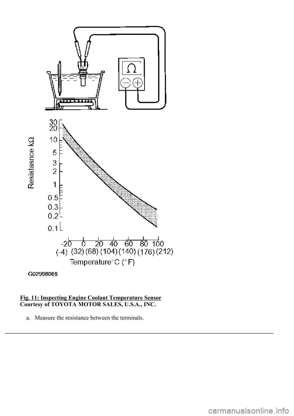
Fig. 11: Inspecting Engine Coolant Temperature Sensor
Courtesy of TOYOTA MOTOR SALES, U.S.A., INC.
a. Measure the resistance between the terminals.
Page 2952 of 4500
STANDARD:
If the result is not as specified, replace the sensor.
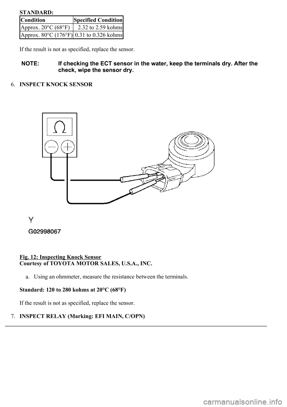
6.INSPECT KNOCK SENSOR
Fig. 12: Inspecting Knock Sensor
Courtesy of TOYOTA MOTOR SALES, U.S.A., INC.
a. Using an ohmmeter, measure the resistance between the terminals.
Standard: 120 to 280 kohms at 20°C (68°F)
If the result is not as specified, replace the sensor.
7.INSPECT RELAY (Marking: EFI MAIN, C/OPN)
ConditionSpecified Condition
Approx. 20°C (68°F)2.32 to 2.59 kohms
Approx. 80°C (176°F)0.31 to 0.326 kohms
Page 2953 of 4500
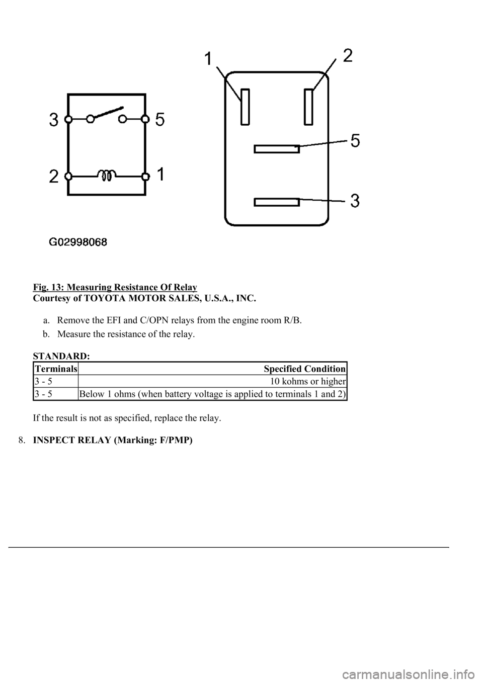
Fig. 13: Measuring Resistance Of Relay
Courtesy of TOYOTA MOTOR SALES, U.S.A., INC.
a. Remove the EFI and C/OPN relays from the engine room R/B.
b. Measure the resistance of the relay.
STANDARD:
If the result is not as specified, replace the relay.
8.INSPECT RELAY (Marking: F/PMP)
TerminalsSpecified Condition
3 - 510 kohms or higher
3 - 5Below 1 ohms (when battery voltage is applied to terminals 1 and 2)
Page 2954 of 4500
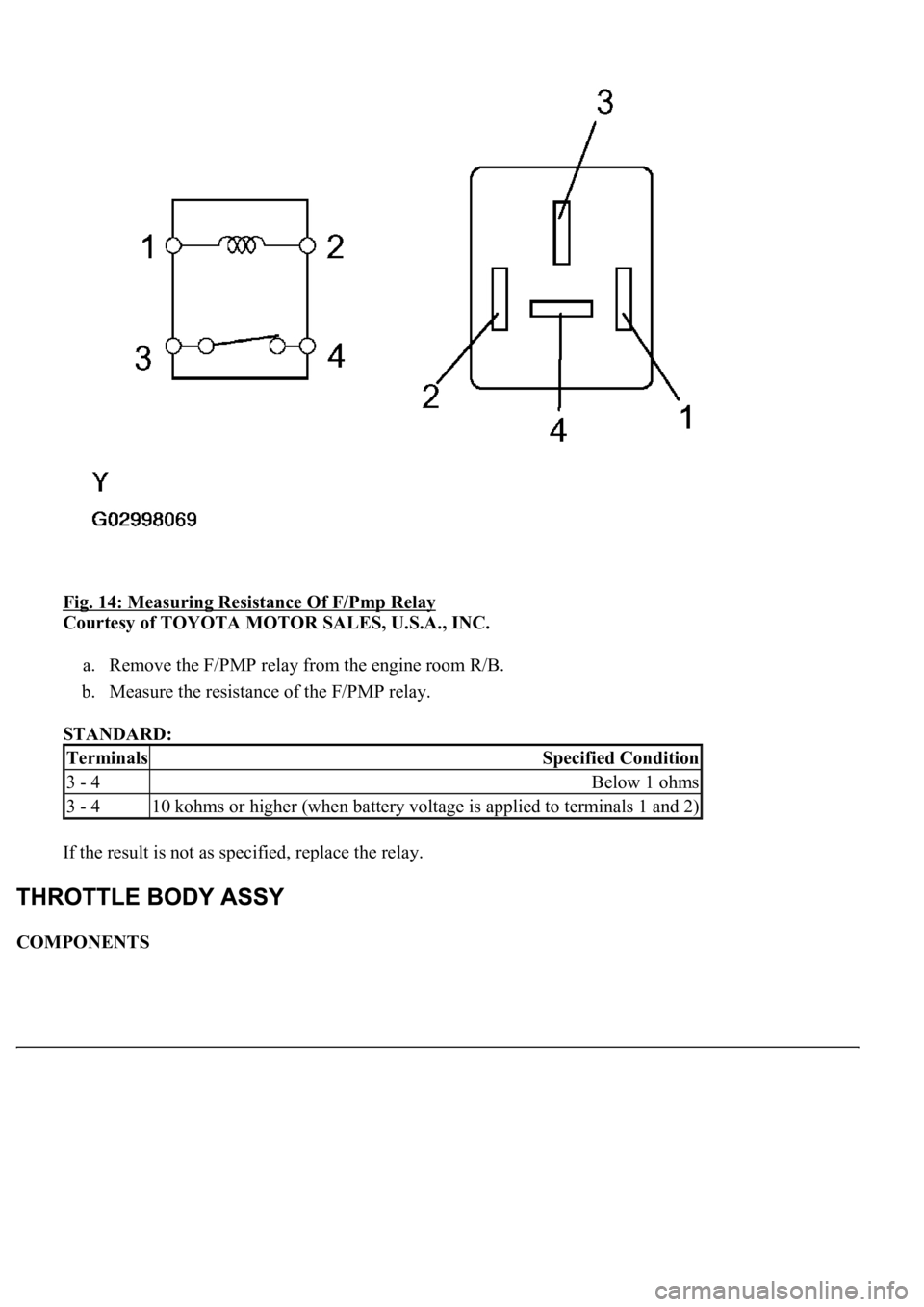
Fig. 14: Measuring Resistance Of F/Pmp Relay
Courtesy of TOYOTA MOTOR SALES, U.S.A., INC.
a. Remove the F/PMP relay from the engine room R/B.
b. Measure the resistance of the F/PMP relay.
STANDARD:
If the result is not as specified, replace the relay.
COMPONENTS
TerminalsSpecified Condition
3 - 4Below 1 ohms
3 - 410 kohms or higher (when battery voltage is applied to terminals 1 and 2)
Page 2955 of 4500
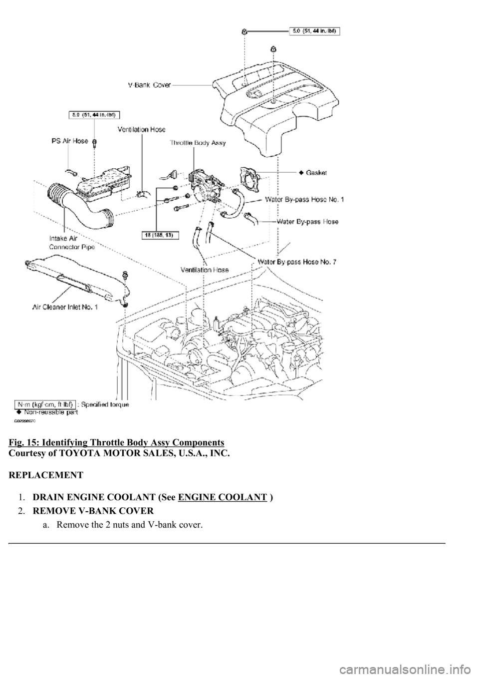
Fig. 15: Identifying Throttle Body Assy Components
Courtesy of TOYOTA MOTOR SALES, U.S.A., INC.
REPLACEMENT
1.DRAIN ENGINE COOLANT (See ENGINE COOLANT
)
2.REMOVE V-BANK COVER
a. Remove the 2 nuts and V-
bank cover.
Page 2956 of 4500
3.REMOVE AIR CLEANER INLET NO.1
4.REMOVE INTAKE AIR CONNECTOR PIPE
a. Disconnect the air hose and ventilation hose.
b. Remove the bolt.
c. Loosen the 2 hose clamps and remove the intake air connector pipe.
5.REMOVE THROTTLE BODY ASSY
Fig. 16: Removing Bolts, Nuts And Throttle Body And Gasket
Courtesy of TOYOTA MOTOR SALES, U.S.A., INC.
a. Disconnect the water bypass hose and water bypass hose No. 7.
b. Disconnect the connector.
c. Remove the 2 bolts, 2 nuts, throttle body and gasket.
6.INSTALL THROTTLE BODY ASSY
Page 2957 of 4500
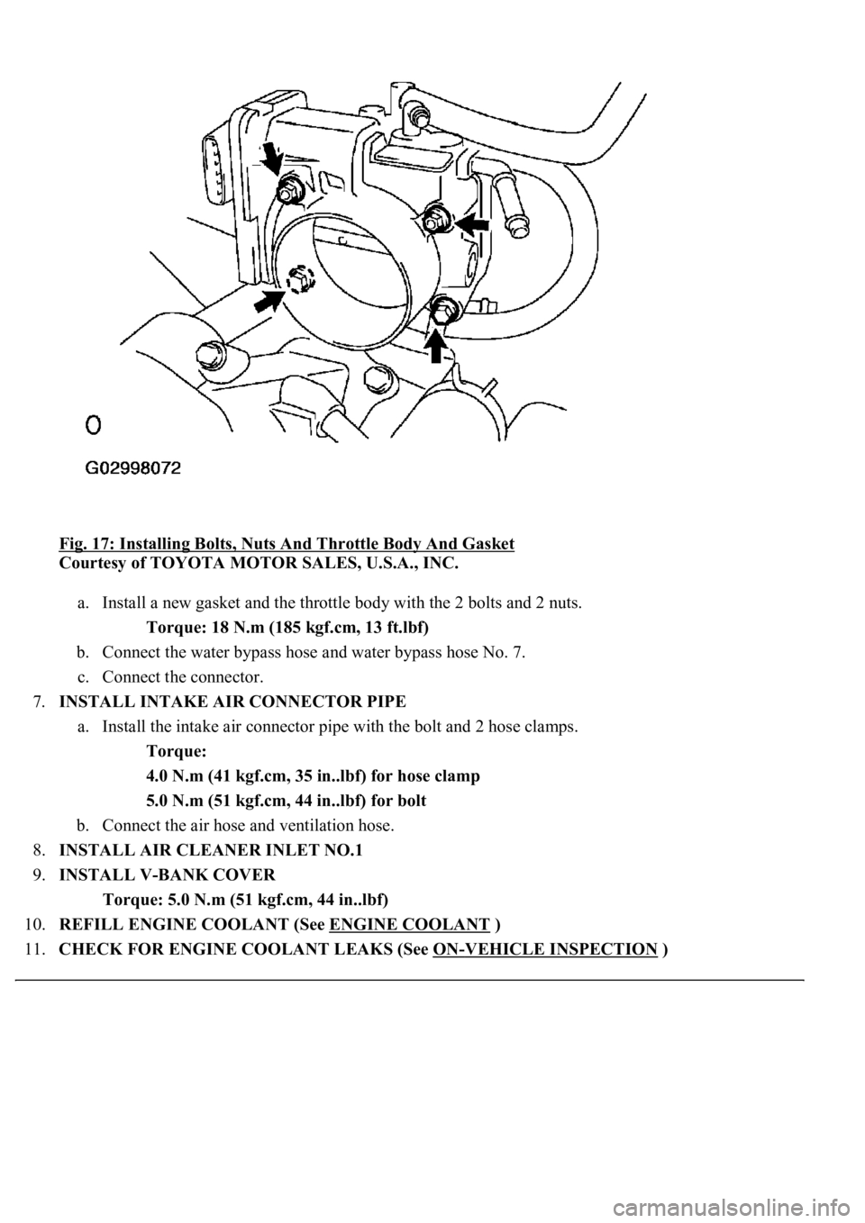
Fig. 17: Installing Bolts, Nuts And Throttle Body And Gasket
Courtesy of TOYOTA MOTOR SALES, U.S.A., INC.
a. Install a new gasket and the throttle body with the 2 bolts and 2 nuts.
Torque: 18 N.m (185 kgf.cm, 13 ft.lbf)
b. Connect the water bypass hose and water bypass hose No. 7.
c. Connect the connector.
7.INSTALL INTAKE AIR CONNECTOR PIPE
a. Install the intake air connector pipe with the bolt and 2 hose clamps.
Torque:
4.0 N.m (41 kgf.cm, 35 in..lbf) for hose clamp
5.0 N.m (51 kgf.cm, 44 in..lbf) for bolt
b. Connect the air hose and ventilation hose.
8.INSTALL AIR CLEANER INLET NO.1
9.INSTALL V-BANK COVER
Torque: 5.0 N.m (51 kgf.cm, 44 in..lbf)
10.REFILL ENGINE COOLANT (See ENGINE COOLANT
)
11.CHECK FOR ENGINE COOLANT LEAKS (See ON
-VEHICLE INSPECTION )
Page 2958 of 4500
12.INSPECT THROTTLE BODY FUNCTION (See ON-VEHICLE INSPECTION )
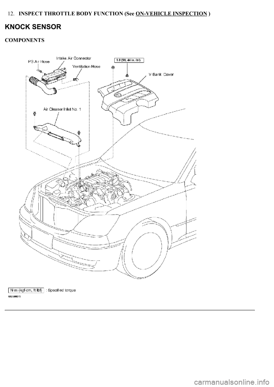
COMPONENTS
Page 2959 of 4500
Fig. 18: Exploded View Of Knock Sensor -Engine Control System Components (1 Of 2)
Courtesy of TOYOTA MOTOR SALES, U.S.A., INC.
Page 2960 of 4500
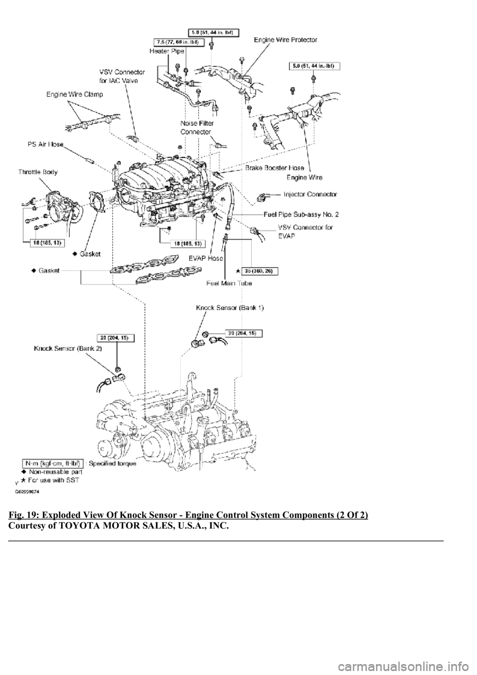
Fig. 19: Exploded View Of Knock Sensor - Engine Control System Components (2 Of 2)
Courtesy of TOYOTA MOTOR SALES, U.S.A., INC.
Trending: instrument cluster, coolant reservoir, radio antenna, steering, climate control, suspension, cruise control
