LEXUS LS430 2003 Factory Repair Manual
Manufacturer: LEXUS, Model Year: 2003, Model line: LS430, Model: LEXUS LS430 2003Pages: 4500, PDF Size: 87.45 MB
Page 3161 of 4500
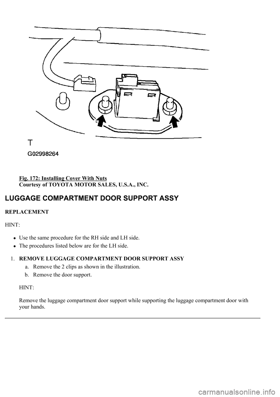
Fig. 172: Installing Cover With Nuts
Courtesy of TOYOTA MOTOR SALES, U.S.A., INC.
REPLACEMENT
HINT:
<00380056004800030057004b0048000300560044005000480003005300550052004600480047005800550048000300490052005500030057004b004800030035002b00030056004c0047004800030044005100470003002f002b00030056004c0047004800
1100030003[
The procedures listed below are for the LH side.
1.REMOVE LUGGAGE COMPARTMENT DOOR SUPPORT ASSY
a. Remove the 2 clips as shown in the illustration.
b. Remove the door support.
HINT:
Remove the luggage compartment door support while supporting the luggage compartment door with
your hands.
Page 3162 of 4500
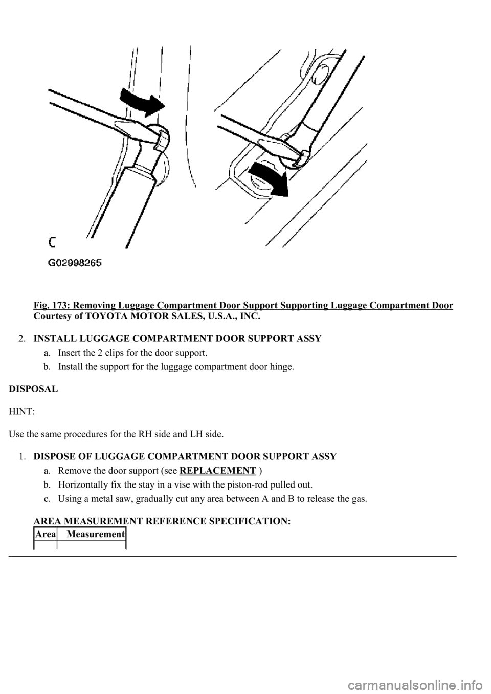
Fig. 173: Removing Luggage Compartment Door Support Supporting Luggage Compartment Door
Courtesy of TOYOTA MOTOR SALES, U.S.A., INC.
2.INSTALL LUGGAGE COMPARTMENT DOOR SUPPORT ASSY
a. Insert the 2 clips for the door support.
b. Install the support for the luggage compartment door hinge.
DISPOSAL
HINT:
Use the same procedures for the RH side and LH side.
1.DISPOSE OF LUGGAGE COMPARTMENT DOOR SUPPORT ASSY
a. Remove the door support (see REPLACEMENT
)
b. Horizontally fix the stay in a vise with the piston-rod pulled out.
c. Using a metal saw, gradually cut any area between A and B to release the gas.
AREA MEASUREMENT REFERENCE SPECIFICATION:
AreaMeasurement
Page 3163 of 4500
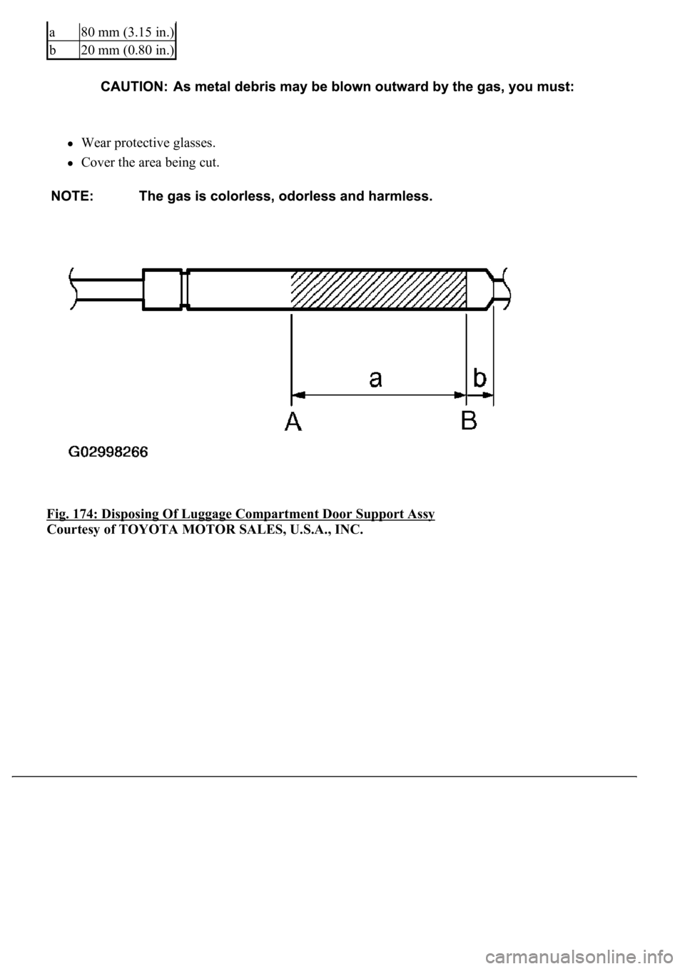
Wear protective glasses.
Cover the area being cut.
Fig. 174: Disposing Of Luggage Compartment Door Support Assy
Courtesy of TOYOTA MOTOR SALES, U.S.A., INC.
a80 mm (3.15 in.)
b20 mm (0.80 in.)
Page 3164 of 4500
SYSTEM REFERENCE TABLE
System NameProceed To
Front Power Seat Control SystemINITIALIZATION
Page 3165 of 4500
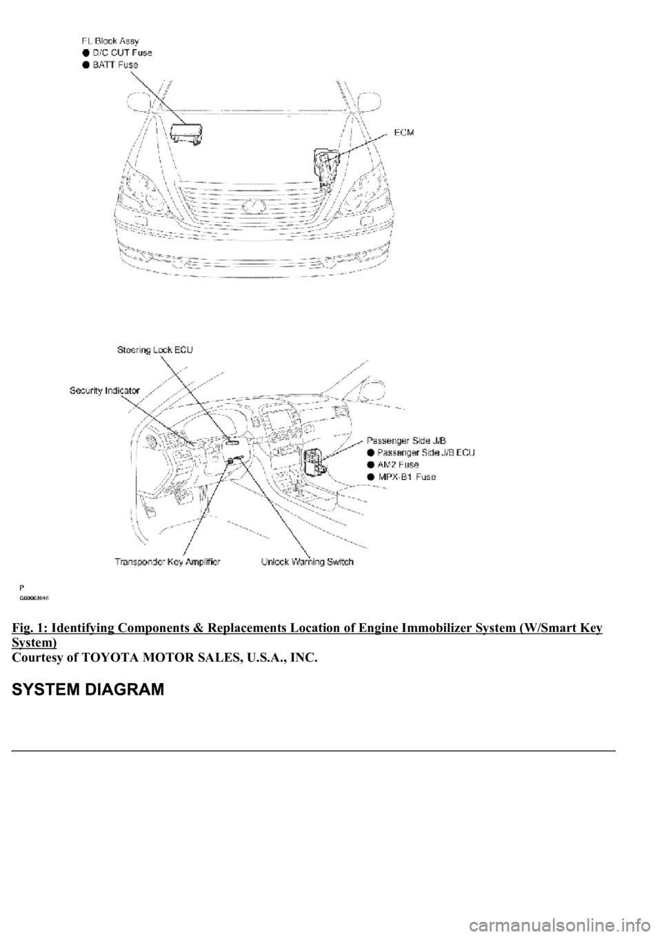
Fig. 1: Identifying Components & Replacements Location of Engine Immobilizer System (W/Smart Key
System)
Courtesy of TOYOTA MOTOR SALES, U.S.A., INC.
Page 3166 of 4500
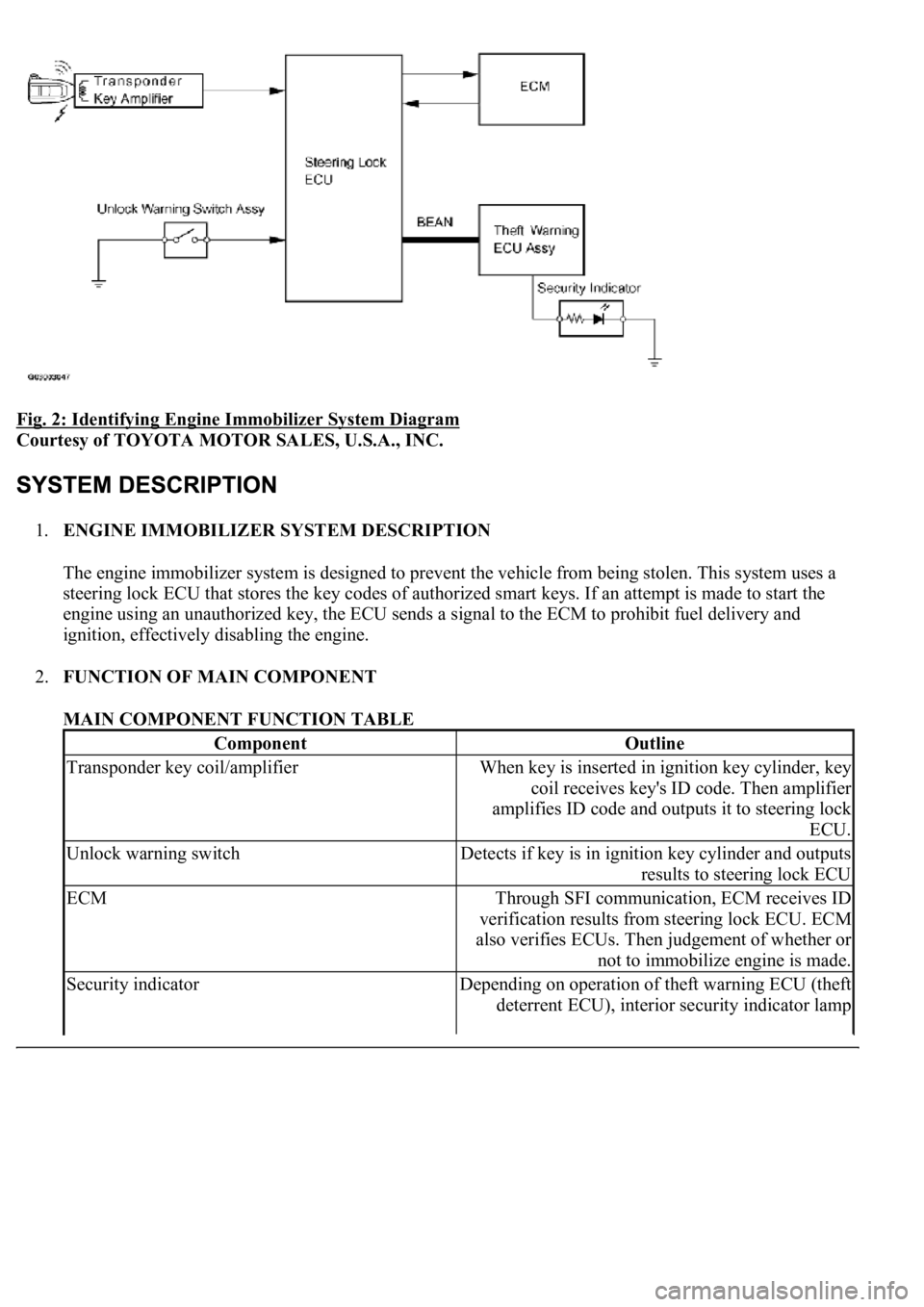
Fig. 2: Identifying Engine Immobilizer System Diagram
Courtesy of TOYOTA MOTOR SALES, U.S.A., INC.
1.ENGINE IMMOBILIZER SYSTEM DESCRIPTION
The engine immobilizer system is designed to prevent the vehicle from being stolen. This system uses a
steering lock ECU that stores the key codes of authorized smart keys. If an attempt is made to start the
engine using an unauthorized key, the ECU sends a signal to the ECM to prohibit fuel delivery and
ignition, effectively disabling the engine.
2.FUNCTION OF MAIN COMPONENT
MAIN COMPONENT FUNCTION TABLE
ComponentOutline
Transponder key coil/amplifierWhen key is inserted in ignition key cylinder, key
coil receives key's ID code. Then amplifier
amplifies ID code and outputs it to steering lock
ECU.
Unlock warning switchDetects if key is in ignition key cylinder and outputs
results to steering lock ECU
ECMThrough SFI communication, ECM receives ID
verification results from steering lock ECU. ECM
also verifies ECUs. Then judgement of whether or
not to immobilize engine is made.
Security indicatorDepending on operation of theft warning ECU (theft
deterrent ECU), interior security indicator lamp
Page 3167 of 4500
3.SYSTEM FUNCTION
When the steering lock ECU detects that the unlock warning switch is ON, the ECU provides current to
the transponder key coil and produces a faint electric wave. A transponder chip in the key and receives
the faint electric wave. Upon receiving the faint electric wave, the transponder chip outputs a key ID code
signal. The transponder key coil receives this signal, the transponder key amplifier amplifies it, and then
the signal is transmitted to the ECU.
The ECU matches the key's ID code with the vehicle's ID code, which was previously registered in the
ECU and then communicates the results to the ECM using SFI communication.
After the identification results show that the key's ID code matches the vehicle's ID code and the ECU has
confirmed their match: 1) the immobilizer system does not immobilize the engine and the engine starting
controls (fuel injection control and ignition control) enter standby mode; and 2) the ECU transmits a
security indicator signal that communicates "indicator off" to the theft warning ECU (theft deterrent
ECU). Then, the theft warning ECU turns off the security indicator lamp.
HINT:
Use this procedure to troubleshoot the engine immobilizer system.
The hand-held tester should be used in steps 4, 5 and 7.
1.VEHICLE BROUGHT TO WORKSHOP
2.CUSTOMER PROBLEM ANALYSIS CHECK AND SYMPTOM CHECK (See CUSTOMER
PROBLEM ANALYSIS CHECK )
3.CRANK ENGINE FOR MORE THAN 10 SECONDS
4.CHECK FOR DTCS
a. Check for DTCs and note any codes that are output.
b. Delete the DTC.
c. Recheck for DTCs. Based on the DTC output in (a), try to force output of the same SFI system
DTC or engine immobilizer system DTC by simulating the operation indicated by the DTC.
1. If the DTC does not reoccur, proceed to A.
2. If the SFI system DTC reoccurs, proceed to B.
3. If the engine immobilizer system DTC reoccurs, proceed to C.
B: Go to SFI SYSTEM (See HOW TO PROCEED WITH TROUBLESHOOTING
)
C: Go to step 8
illuminates or starts blinking.
Page 3168 of 4500
A: Go to next step
5.READ DATA LIST USING HAND-HELD TESTER
a. Connect the hand-held tester to the Controller Area Network Vehicle Interface Module (CAN
VIM). Then connect the CAN VIM to the DLC3.
b. Turn the ignition switch ON and push the hand-held tester main switch ON.
c. Read the DATA LIST.
Steering lock ECU:
DATA LIST - STEERING LOCK ECU
OK: "ON" (Key is in ignition key cylinder) appears on the screen.
NG: Go to DTC B2780 (See DTC B2780 PUSH SWITCH/KEY UNLOCK WARNING SWITCH
MALFUNCTION )
OK: Go to next step
6.See PROBLEM SYMPTOMS TABLE
)
a. If the fault is not listed on the problem symptoms table, proceed to A.
b. If the fault is listed on the problem symptoms table, proceed to B.
B: Go to step 8
A: Go to next step
7.OVERALL ANALYSIS AND TROUBLESHOOTING
a. See DATA LIST/ACTIVE TEST
)
1. Inspection with the hand-held tester (DATA LIST)
2. Inspection with the hand-held tester (ACTIVE TEST)
b. See TERMINALS OF ECU
)
8.ADJUST, REPAIR OR REPLACE
9.CONFIRMATION TEST
END
Item
Measurement Item/
Display (Range)
Normal ConditionDiagnostic Note
KEY SWUnlock warning switch
signal/ ON or OFFON: Key is in ignition
key cylinder OFF: No
key is in ignition key
cylinder-
Page 3169 of 4500
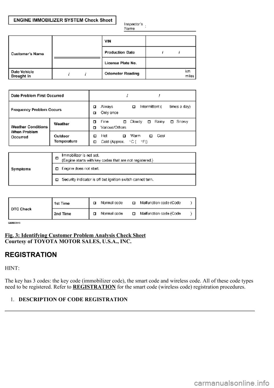
Fig. 3: Identifying Customer Problem Analysis Check Sheet
Courtesy of TOYOTA MOTOR SALES, U.S.A., INC.
HINT:
The key has 3 codes: the key code (immobilizer code), the smart code and wireless code. All of these code types
need to be registered. Refer to REGISTRATION
for the smart code (wireless code) registration procedures.
1.DESCRIPTION OF CODE REGISTRATION
Page 3170 of 4500
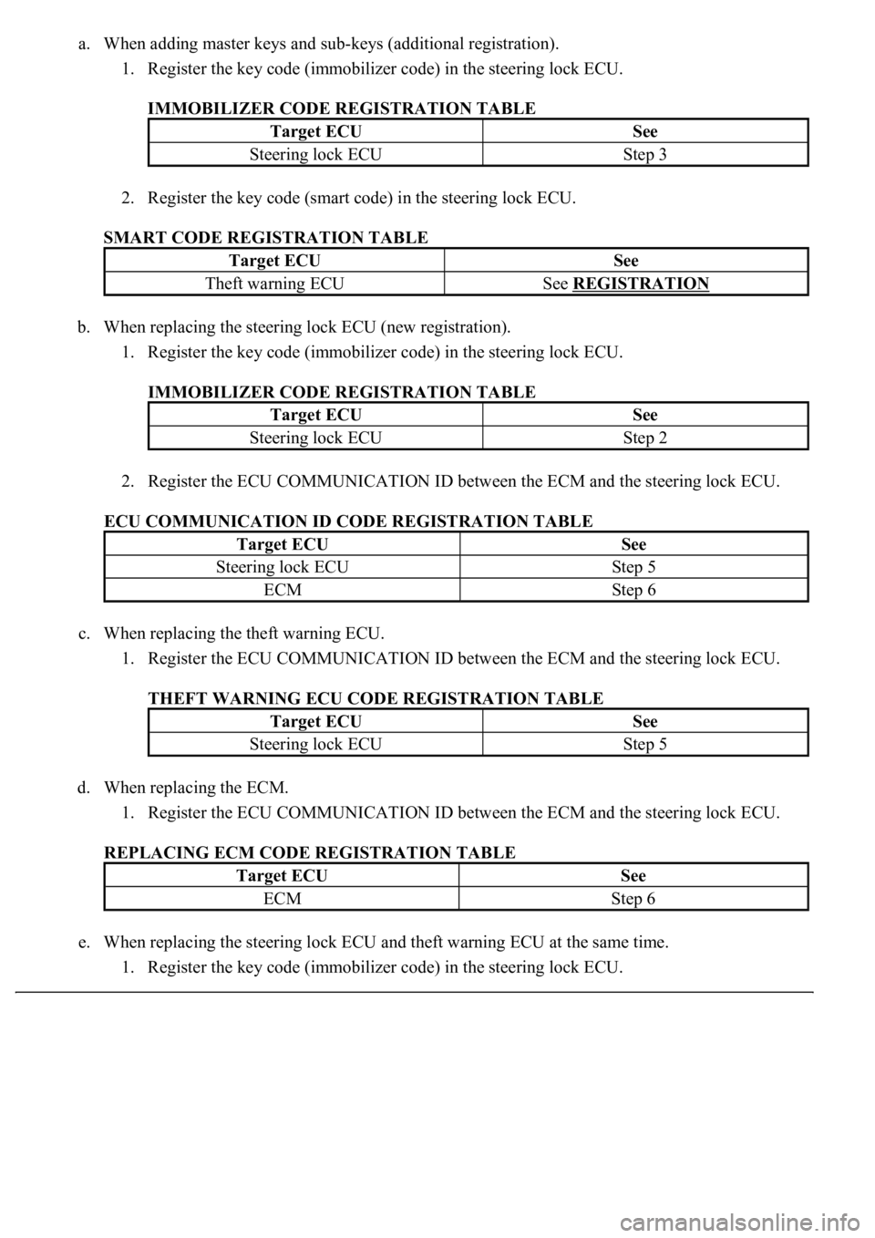
a. When adding master keys and sub-keys (additional registration).
1. Register the key code (immobilizer code) in the steering lock ECU.
IMMOBILIZER CODE REGISTRATION TABLE
2. Register the key code (smart code) in the steering lock ECU.
SMART CODE REGISTRATION TABLE
b. When replacing the steering lock ECU (new registration).
1. Register the key code (immobilizer code) in the steering lock ECU.
IMMOBILIZER CODE REGISTRATION TABLE
2. Register the ECU COMMUNICATION ID between the ECM and the steering lock ECU.
ECU COMMUNICATION ID CODE REGISTRATION TABLE
c. When replacing the theft warning ECU.
1. Register the ECU COMMUNICATION ID between the ECM and the steering lock ECU.
THEFT WARNING ECU CODE REGISTRATION TABLE
d. When replacing the ECM.
1. Register the ECU COMMUNICATION ID between the ECM and the steering lock ECU.
REPLACING ECM CODE REGISTRATION TABLE
e. When replacing the steering lock ECU and theft warning ECU at the same time.
1. Register the key code (immobilizer code) in the steering lock ECU.
Target ECUSee
Steering lock ECUStep 3
Target ECUSee
Theft warning ECUSee REGISTRATION
Target ECUSee
Steering lock ECUStep 2
Target ECUSee
Steering lock ECUStep 5
ECMStep 6
Target ECUSee
Steering lock ECUStep 5
Target ECUSee
ECMStep 6