LEXUS LS430 2003 Factory Repair Manual
Manufacturer: LEXUS, Model Year: 2003,
Model line: LS430,
Model: LEXUS LS430 2003
Pages: 4500, PDF Size: 87.45 MB
LEXUS LS430 2003 Factory Repair Manual
LS430 2003
LEXUS
LEXUS
https://www.carmanualsonline.info/img/36/57050/w960_57050-0.png
LEXUS LS430 2003 Factory Repair Manual
Trending: Ecm, content, check engine light, coolant capacity, B2419 bean, park, transmission oil
Page 3201 of 4500
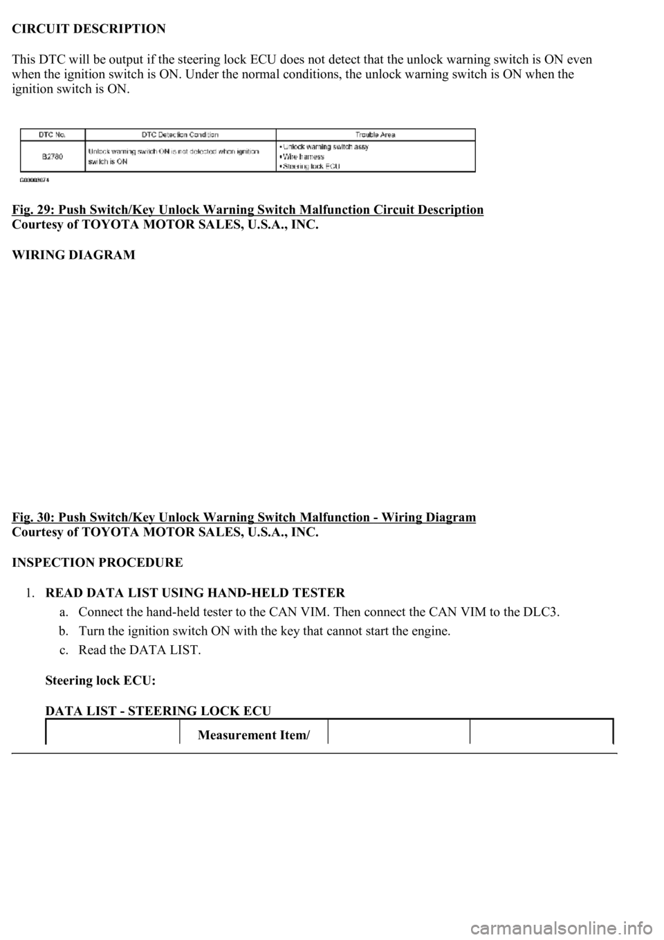
CIRCUIT DESCRIPTION
This DTC will be output if the steering lock ECU does not detect that the unlock warning switch is ON even
when the ignition switch is ON. Under the normal conditions, the unlock warning switch is ON when the
ignition switch is ON.
Fig. 29: Push Switch/Key Unlock Warning Switch Malfunction Circuit Description
Courtesy of TOYOTA MOTOR SALES, U.S.A., INC.
WIRING DIAGRAM
Fig. 30: Push Switch/Key Unlock Warning Switch Malfunction
- Wiring Diagram
Courtesy of TOYOTA MOTOR SALES, U.S.A., INC.
INSPECTION PROCEDURE
1.READ DATA LIST USING HAND-HELD TESTER
a. Connect the hand-held tester to the CAN VIM. Then connect the CAN VIM to the DLC3.
b. Turn the ignition switch ON with the key that cannot start the engine.
c. Read the DATA LIST.
Steering lock ECU:
DATA LIST - STEERING LOCK ECU
Measurement Item/
Page 3202 of 4500
OK: "ON" (Key is in ignition key cylinder) appears on the screen.
NG: Go to step 2
OK: REPLACE STEERING LOCK ECU
2.INSPECT UNLOCK WARNING SWITCH ASSY
a. Remove the unlock warning switch.
b. Measure the resistance of the switch.
Standard:
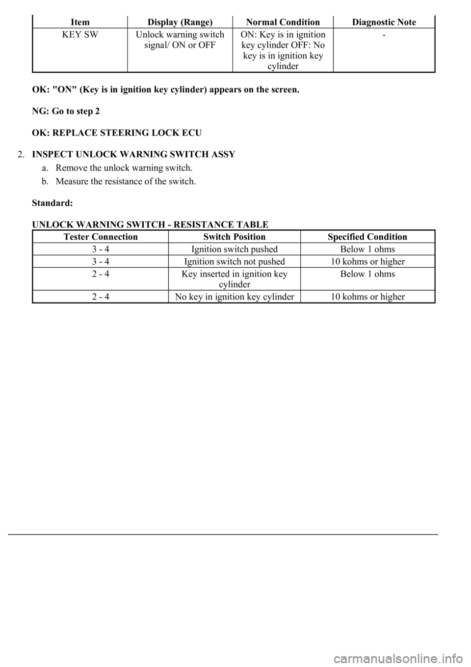
UNLOCK WARNING SWITCH - RESISTANCE TABLE
ItemDisplay (Range)Normal ConditionDiagnostic Note
KEY SWUnlock warning switch
signal/ ON or OFFON: Key is in ignition
key cylinder OFF: No
key is in ignition key
cylinder-
Tester ConnectionSwitch PositionSpecified Condition
3 - 4Ignition switch pushedBelow 1 ohms
3 - 4Ignition switch not pushed10 kohms or higher
2 - 4Key inserted in ignition key
cylinderBelow 1 ohms
2 - 4No key in ignition key cylinder10 kohms or higher
Page 3203 of 4500
Fig. 31: Inspecting Unlock Warning Switch Assy
Courtesy of TOYOTA MOTOR SALES, U.S.A., INC.
NG: REPLACE UNLOCK WARNING SWITCH ASSY
OK: Go to next step
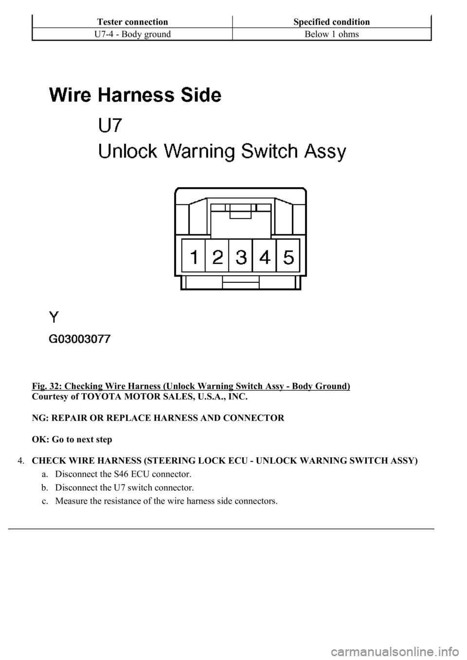
3.CHECK WIRE HARNESS (UNLOCK WARNING SWITCH ASSY - BODY GROUND)
a. Disconnect the U7 switch connector.
b. Measure the resistance of the wire harness side connector.
Standard:
UNLOCK WARNING SWITCH ASSY - BODY GROUND - RESISTANCE TABLE
Page 3204 of 4500
Fig. 32: Checking Wire Harness (Unlock Warning Switch Assy - Body Ground)
Courtesy of TOYOTA MOTOR SALES, U.S.A., INC.
NG: REPAIR OR REPLACE HARNESS AND CONNECTOR
OK: Go to next step
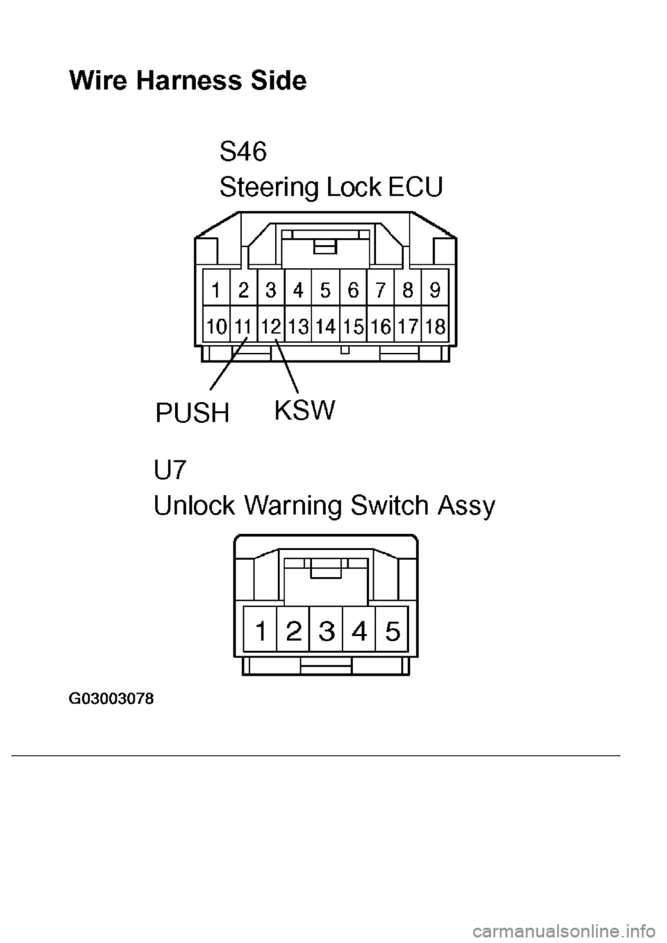
4.CHECK WIRE HARNESS (STEERING LOCK ECU - UNLOCK WARNING SWITCH ASSY)
a. Disconnect the S46 ECU connector.
b. Disconnect the U7 switch connector.
c. Measure the resistance of the wire harness side connectors.
Tester connectionSpecified condition
U7-4 - Body groundBelow 1 ohms
Page 3205 of 4500
Standard:
STEERING LOCK ECU - UNLOCK WARNING SWITCH - RESISTANCE TABLE
Tester connectionSpecified condition
S46-12 (KSW) - U7-2Below 1 ohms
S46-11 (PUSH) - U7-3Below 1 ohms
Page 3206 of 4500
Page 3207 of 4500
Fig. 33: Checking Wire Harness (Steering Lock ECU -Unlock Warning Switch Assy)
Courtesy of TOYOTA MOTOR SALES, U.S.A., INC.
NG: REPAIR OR REPLACE HARNESS AND CONNECTOR
OK: REPLACE STEERING LOCK ECU
CIRCUIT DESCRIPTION
This DTC is output when: 1) during the key code registration, a key malfunction occurs; or 2) the key code was
unable to be registered properly. Follow the inspection procedure below.
TRANSPONDER CHIP MALFUNCTION DTC REFERENCE TABLE
INSPECTION PROCEDURE
1.RE-REGISTER KEY
a. Delete the DTC (See DTC CHECK/CLEAR
).
b. Re-register the key (See REGISTRATION
), and check that the engine starts with the key.
OK: Engine starts.
NG: REPLACE KEY
OK: NORMAL (INSPECTION FINISHED)
CIRCUIT DESCRIPTION
This DTC is output when a key with an incomplete key code is inserted into the ignition key cylinder.
UNMATCHED ENCRYPTION CODE DTC REFERENCE TABLE
INSPECTION PROCEDURE
REPLACE KEY
DTC No.DTC Detection ConditionTrouble Area
B2793Transponder chip malfunctionSmart key
DTC No.DTC Detection ConditionTrouble Area
B2794Key with incomplete key code is
insertedSmart key
Page 3208 of 4500
CIRCUIT DESCRIPTION
This DTC is output when a key with a key code that has not been registered in the ECU is inserted into the
ignition key cylinder.
UNMATCHED KEY CODE DTC REFERENCE TABLE
INSPECTION PROCEDURE
1.DELETE DTC AND INSERT ALL PRESENTLY AVAILABLE KEYS TO CHECK WHETHER
ENGINE STARTS OR NOT
OK: Engine starts.
NG: REPLACE KEY THAT CANNOT START ENGINE
OK: NO PROBLEM (BECAUSE OF KEY RE-REGISTRATION)
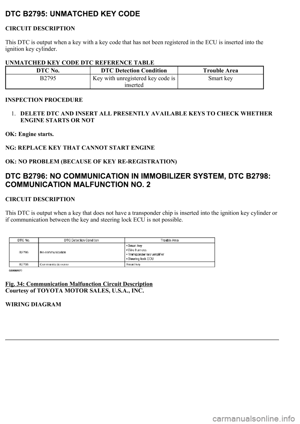
CIRCUIT DESCRIPTION
This DTC is output when a key that does not have a transponder chip is inserted into the ignition key cylinder or
if communication between the key and steering lock ECU is not possible.
Fig. 34: Communication Malfunction Circuit Description
Courtesy of TOYOTA MOTOR SALES, U.S.A., INC.
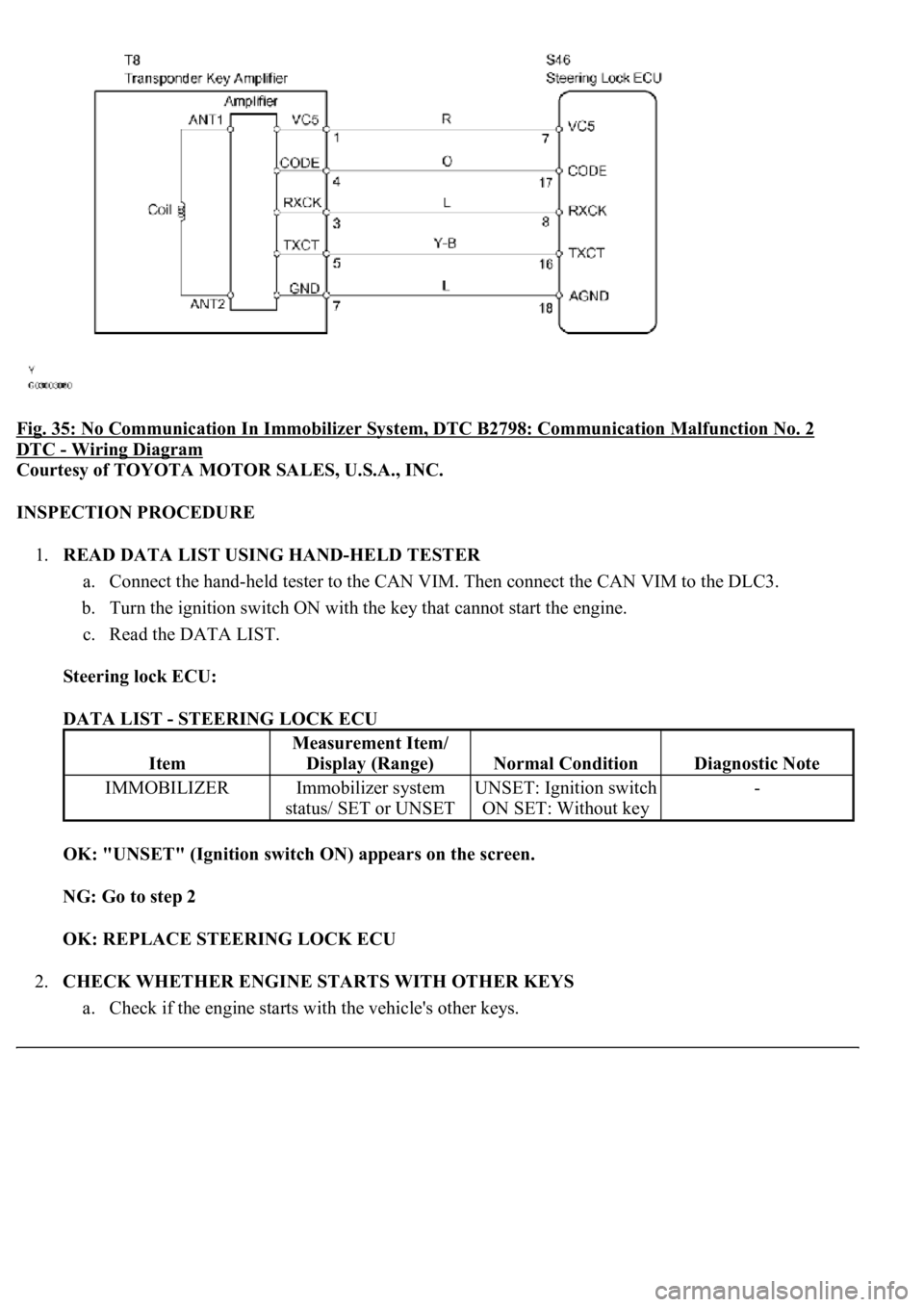
WIRING DIAGRAM
DTC No.DTC Detection ConditionTrouble Area
B2795Key with unregistered key code is
insertedSmart key
Page 3209 of 4500
Fig. 35: No Communication In Immobilizer System, DTC B2798: Communication Malfunction No. 2
DTC - Wiring Diagram
Courtesy of TOYOTA MOTOR SALES, U.S.A., INC.
INSPECTION PROCEDURE
1.READ DATA LIST USING HAND-HELD TESTER
a. Connect the hand-held tester to the CAN VIM. Then connect the CAN VIM to the DLC3.
b. Turn the ignition switch ON with the key that cannot start the engine.
c. Read the DATA LIST.
Steering lock ECU:
DATA LIST - STEERING LOCK ECU
OK: "UNSET" (Ignition switch ON) appears on the screen.
NG: Go to step 2
OK: REPLACE STEERING LOCK ECU
2.CHECK WHETHER ENGINE STARTS WITH OTHER KEYS
a. Check if the en
gine starts with the vehicle's other keys.
Item
Measurement Item/
Display (Range)
Normal ConditionDiagnostic Note
IMMOBILIZERImmobilizer system
status/ SET or UNSETUNSET: Ignition switch
ON SET: Without key-
Page 3210 of 4500
OK: Engine starts.
NG: Go to step 3
OK: RE-REGISTER OR REPLACE KEY THAT CANNOT START ENGINE
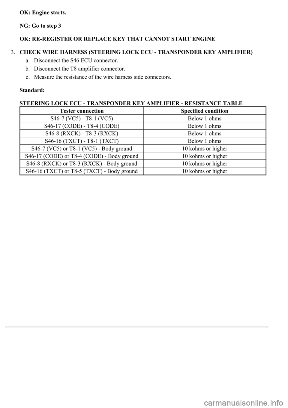
3.CHECK WIRE HARNESS (STEERING LOCK ECU - TRANSPONDER KEY AMPLIFIER)
a. Disconnect the S46 ECU connector.
b. Disconnect the T8 amplifier connector.
c. Measure the resistance of the wire harness side connectors.
Standard:
STEERING LOCK ECU - TRANSPONDER KEY AMPLIFIER - RESISTANCE TABLE
Tester connectionSpecified condition
S46-7 (VC5) - T8-1 (VC5)Below 1 ohms
S46-17 (CODE) - T8-4 (CODE)Below 1 ohms
S46-8 (RXCK) - T8-3 (RXCK)Below 1 ohms
S46-16 (TXCT) - T8-1 (TXCT)Below 1 ohms
S46-7 (VC5) or T8-1 (VC5) - Body ground10 kohms or higher
S46-17 (CODE) or T8-4 (CODE) - Body ground10 kohms or higher
S46-8 (RXCK) or T8-3 (RXCK) - Body ground10 kohms or higher
S46-16 (TXCT) or T8-5 (TXCT) - Body ground10 kohms or higher
Trending: battery, Sp2, content, Suspension control, wiring, injection, warning lights
