LEXUS LS430 2003 Factory Repair Manual
Manufacturer: LEXUS, Model Year: 2003,
Model line: LS430,
Model: LEXUS LS430 2003
Pages: 4500, PDF Size: 87.45 MB
LEXUS LS430 2003 Factory Repair Manual
LS430 2003
LEXUS
LEXUS
https://www.carmanualsonline.info/img/36/57050/w960_57050-0.png
LEXUS LS430 2003 Factory Repair Manual
Trending: brake fluid, maintenance reset, spare tire, Spark plug firing order, Skid, manual transmission, clock
Page 3121 of 4500
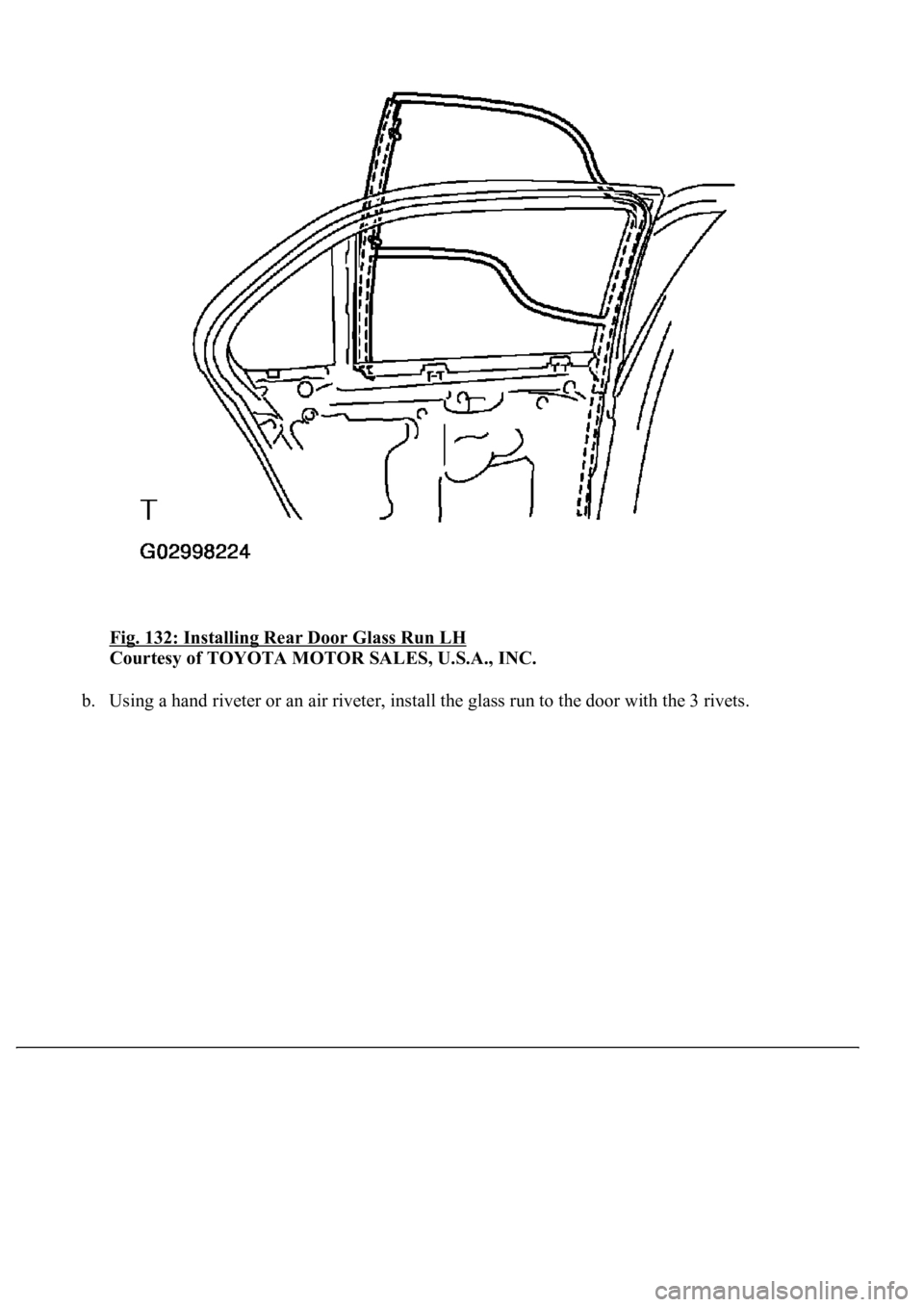
Fig. 132: Installing Rear Door Glass Run LH
Courtesy of TOYOTA MOTOR SALES, U.S.A., INC.
b.Using a hand riveter or an air riveter, install the glass run to the door with the 3 rivets.
Page 3122 of 4500
Fig. 133: Installing Glass Run To Door With Rivets
Courtesy of TOYOTA MOTOR SALES, U.S.A., INC.
Page 3123 of 4500
Page 3124 of 4500
Page 3125 of 4500
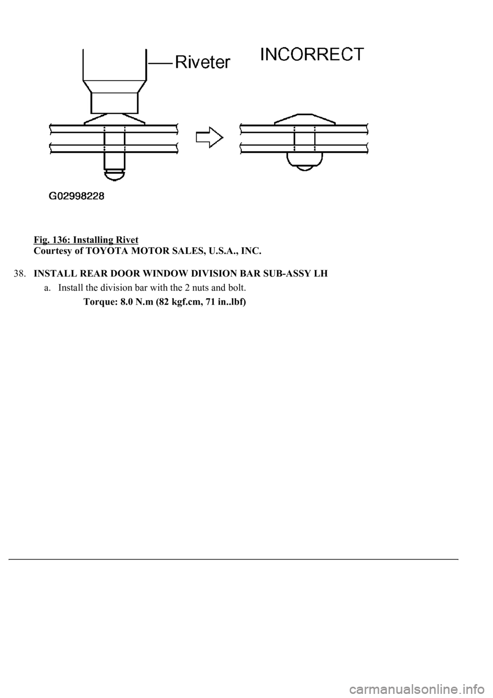
Fig. 136: Installing Rivet
Courtesy of TOYOTA MOTOR SALES, U.S.A., INC.
38.INSTALL REAR DOOR WINDOW DIVISION BAR SUB-ASSY LH
a. Install the division bar with the 2 nuts and bolt.
Torque: 8.0 N.m (82 kgf.cm, 71 in..lbf)
Page 3126 of 4500
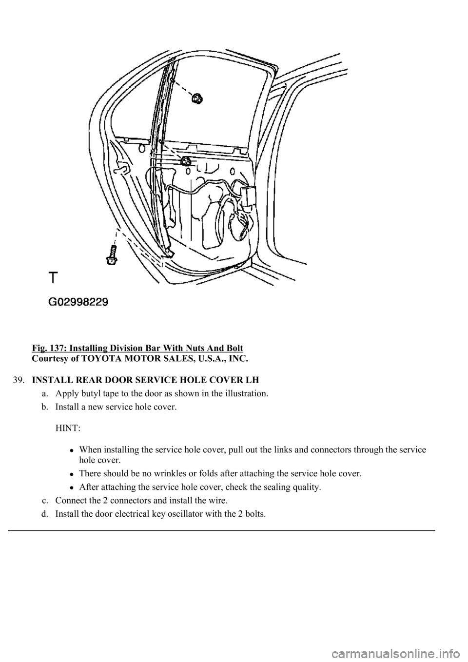
Fig. 137: Installing Division Bar With Nuts And Bolt
Courtesy of TOYOTA MOTOR SALES, U.S.A., INC.
39.INSTALL REAR DOOR SERVICE HOLE COVER LH
a. Apply butyl tape to the door as shown in the illustration.
b. Install a new service hole cover.
HINT:
When installing the service hole cover, pull out the links and connectors through the service
hole cover.
There should be no wrinkles or folds after attaching the service hole cover.
After attaching the service hole cover, check the sealing quality.
c. Connect the 2 connectors and install the wire.
d. Install the door electrical ke
y oscillator with the 2 bolts.
Page 3127 of 4500
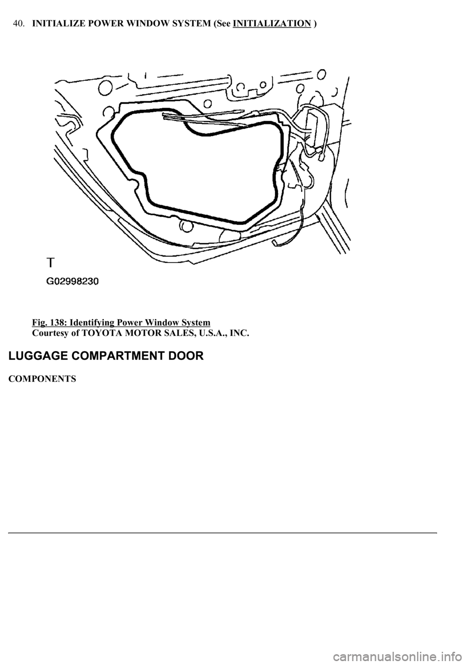
40.INITIALIZE POWER WINDOW SYSTEM (See INITIALIZATION )
Fig. 138: Identifying Power Window System
Courtesy of TOYOTA MOTOR SALES, U.S.A., INC.
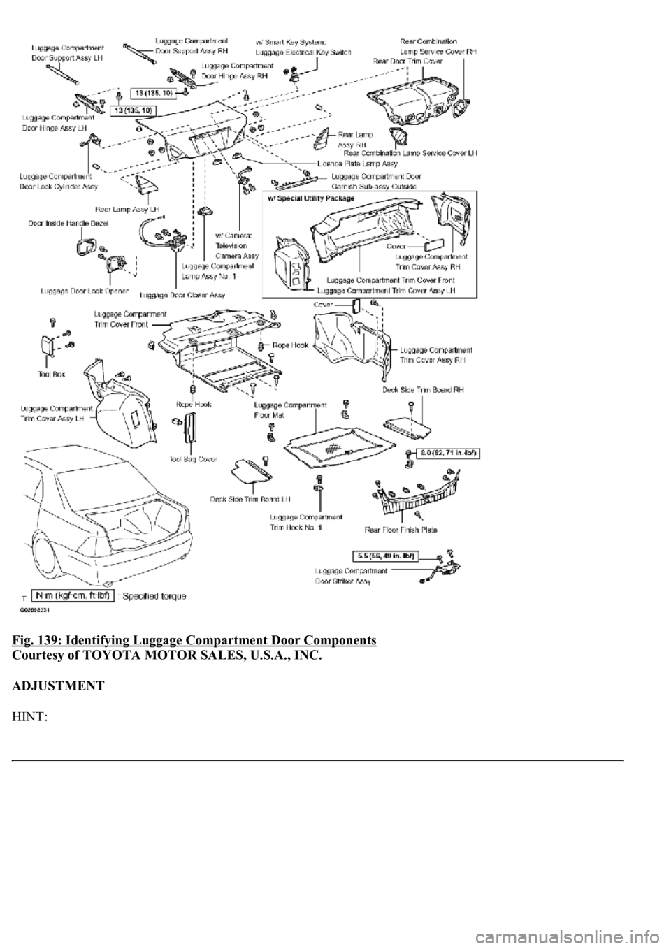
COMPONENTS
Page 3128 of 4500
Fig. 139: Identifying Luggage Compartment Door Components
Courtesy of TOYOTA MOTOR SALES, U.S.A., INC.
ADJUSTMENT
HINT:
Page 3129 of 4500
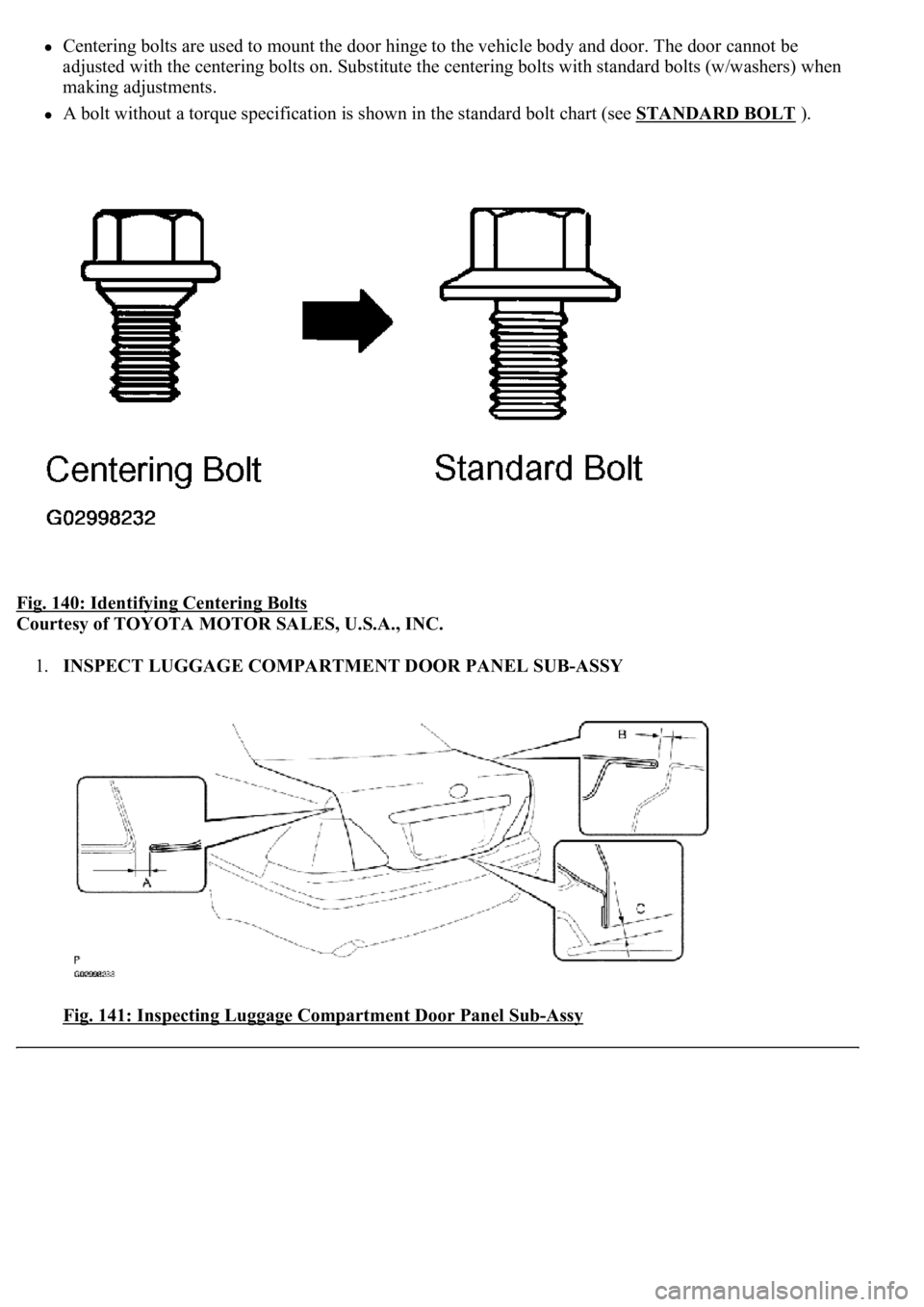
Centering bolts are used to mount the door hinge to the vehicle body and door. The door cannot be
adjusted with the centering bolts on. Substitute the centering bolts with standard bolts (w/washers) when
making adjustments.
A bolt without a torque specification is shown in the standard bolt chart (see STANDARD BOLT ).
Fig. 140: Identifying Centering Bolts
Courtesy of TOYOTA MOTOR SALES, U.S.A., INC.
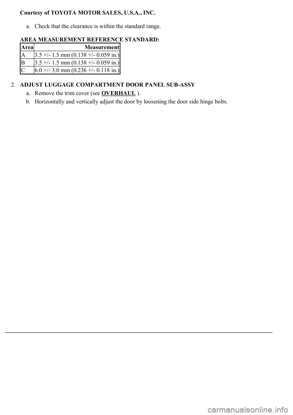
1.INSPECT LUGGAGE COMPARTMENT DOOR PANEL SUB-ASSY
Fig. 141: Inspecting Luggage Compartment Door Panel Sub
-Assy
Page 3130 of 4500
Courtesy of TOYOTA MOTOR SALES, U.S.A., INC.
a. Check that the clearance is within the standard range.
AREA MEASUREMENT REFERENCE STANDARD:
2.ADJUST LUGGAGE COMPARTMENT DOOR PANEL SUB-ASSY
a. Remove the trim cover (see OVERHAUL
).
b. Horizontally and vertically adjust the door by loosening the door side hinge bolts.
AreaMeasurement
A3.5 +/- 1.5 mm (0.138 +/- 0.059 in.)
B3.5 +/- 1.5 mm (0.138 +/- 0.059 in.)
C6.0 +/- 3.0 mm (0.236 +/- 0.118 in.)
Trending: navigation update, engine oil, ignition, park, electronic modulated, wheel bolts, Control actuator
