LEXUS LS430 2003 Factory Repair Manual
Manufacturer: LEXUS, Model Year: 2003,
Model line: LS430,
Model: LEXUS LS430 2003
Pages: 4500, PDF Size: 87.45 MB
LEXUS LS430 2003 Factory Repair Manual
LS430 2003
LEXUS
LEXUS
https://www.carmanualsonline.info/img/36/57050/w960_57050-0.png
LEXUS LS430 2003 Factory Repair Manual
Trending: B2402, electronic modulated, air bleeding, power steering fluid, parking brake, mirror, B2799
Page 3171 of 4500
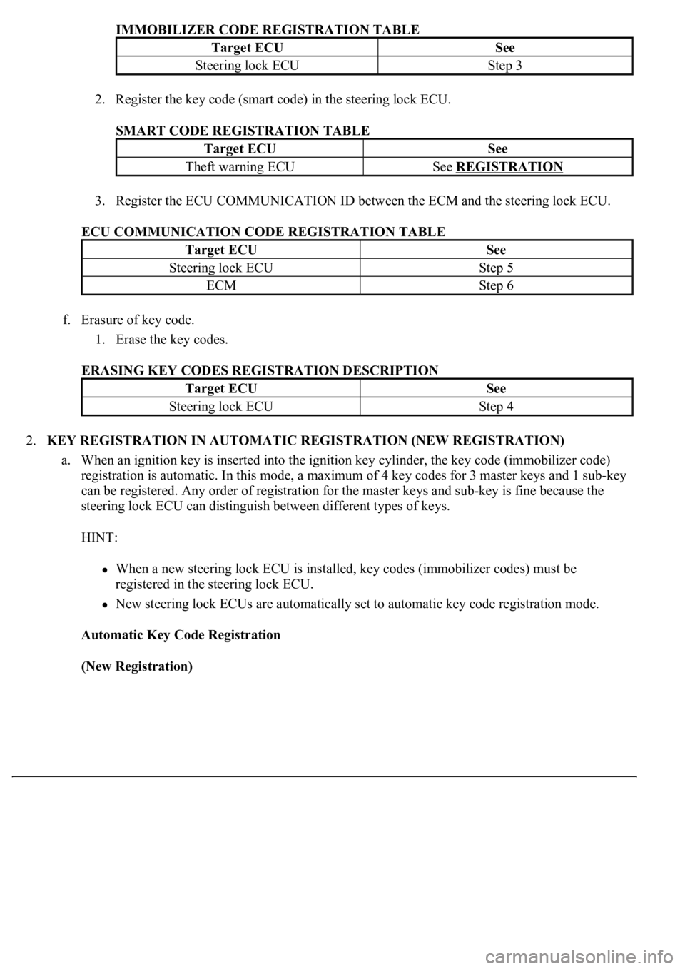
IMMOBILIZER CODE REGISTRATION TABLE
2. Register the key code (smart code) in the steering lock ECU.
SMART CODE REGISTRATION TABLE
3. Register the ECU COMMUNICATION ID between the ECM and the steering lock ECU.
ECU COMMUNICATION CODE REGISTRATION TABLE
f. Erasure of key code.
1. Erase the key codes.
ERASING KEY CODES REGISTRATION DESCRIPTION
2.KEY REGISTRATION IN AUTOMATIC REGISTRATION (NEW REGISTRATION)
a. When an ignition key is inserted into the ignition key cylinder, the key code (immobilizer code)
registration is automatic. In this mode, a maximum of 4 key codes for 3 master keys and 1 sub-key
can be registered. Any order of registration for the master keys and sub-key is fine because the
steering lock ECU can distinguish between different types of keys.
HINT:
When a new steering lock ECU is installed, key codes (immobilizer codes) must be
registered in the steering lock ECU.
New steering lock ECUs are automatically set to automatic key code registration mode.
Automatic Key Code Registration
(New Registration)
Target ECUSee
Steering lock ECUStep 3
Target ECUSee
Theft warning ECUSee REGISTRATION
Target ECUSee
Steering lock ECUStep 5
ECMStep 6
Target ECUSee
Steering lock ECUStep 4
Page 3172 of 4500
Fig. 4: Automatic Key Code Registration Flowchart (New Registration)
Courtesy of TOYOTA MOTOR SALES, U.S.A., INC.
HINT:
When no key is inserted into the ignition key cylinder in automatic key code registration
mode, the security indicator remains on.
When the immobilizer system is operating normally and the key is pulled out, the security
indicator blinks continuously.
If the key code registration has failed in automatic key code registration mode, code 2-1 will
be output from the security indicator. Trying to re-register an already registered key will
cause code 2-2 to be output when the key is inserted. If the number of registered key codes
Page 3173 of 4500
exceeds the limit, code 2-3 will be output from the security indicator. The output details are
shown below.
Security Indicator
Fig. 5: Automatic Key Code Registration Output Codes (Security Indicator)
Courtesy of TOYOTA MOTOR SALES, U.S.A., INC.
b. Finish the automatic key code registration mode.
Page 3174 of 4500
HINT:
The automatic key code registration mode can be forced to end when at least 1 key code (immobilizer
code) for the master key has been registered.
3.REGISTRATION OF ADDITIONAL KEY (ADDITIONAL REGISTRATION)
a. Register an additional key using the hand-held tester.
HINT:
A maximum of 5 master key codes and 3 sub-key codes can be registered.
Registration mode will end if each step is not completed within the specified time.
When the ignition cylinder or the key cylinder set is replaced, remove the transmitter module
from the original master key. Then install this transmitter module to a new key and use the
new key as the master key. If necessary, use this master key to register other keys.
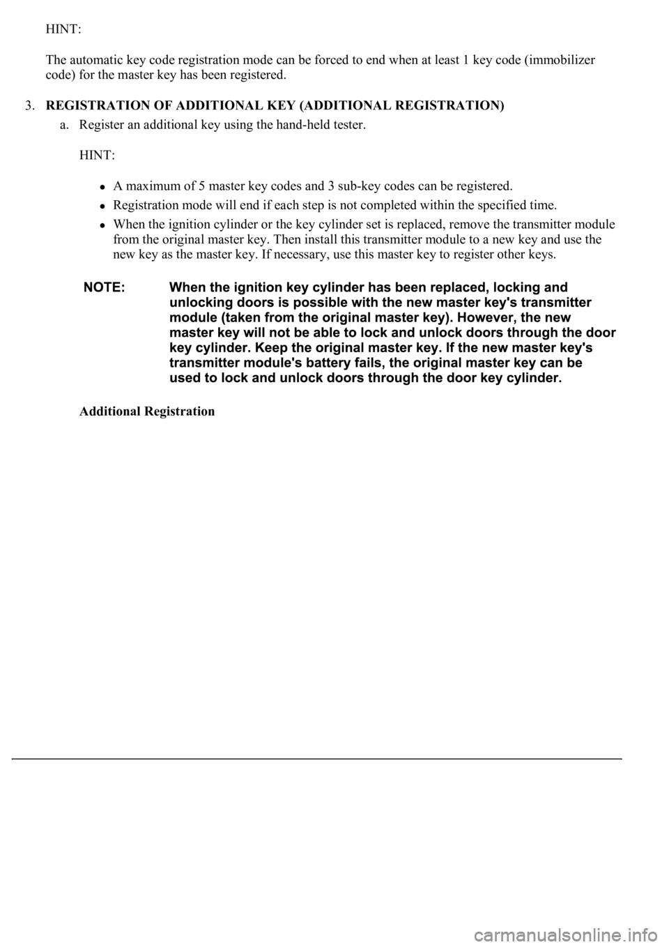
Additional Registration
Page 3175 of 4500
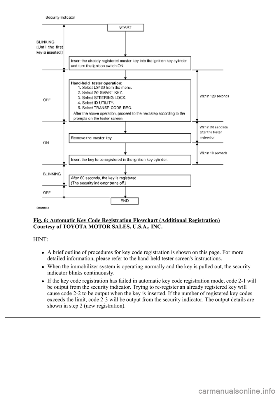
Fig. 6: Automatic Key Code Registration Flowchart (Additional Registration)
Courtesy of TOYOTA MOTOR SALES, U.S.A., INC.
HINT:
A brief outline of procedures for key code registration is shown on this page. For more
detailed information, please refer to the hand-held tester screen's instructions.
When the immobilizer system is operating normally and the key is pulled out, the security
indicator blinks continuously.
If the key code registration has failed in automatic key code registration mode, code 2-1 will
be output from the security indicator. Trying to re-register an already registered key will
cause code 2-2 to be output when the key is inserted. If the number of registered key codes
exceeds the limit, code 2-3 will be output from the security indicator. The output details are
shown in step 2 (new re
gistration).
Page 3176 of 4500
4.ERASURE OF KEY CODE
a. Erase key codes using the hand-held tester.
HINT:
All key codes are erased except for the master key, which is used for erasing the key codes.
In order to use a key whose code has been erased, a new key code must be registered.
Registration will be cancelled if each step is not completed within the specified time.
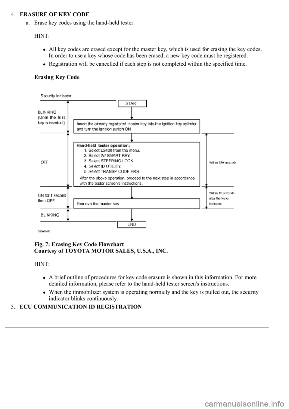
Erasing Key Code
Fig. 7: Erasing Key Code Flowchart
Courtesy of TOYOTA MOTOR SALES, U.S.A., INC.
HINT:
A brief outline of procedures for key code erasure is shown in this information. For more
detailed information, please refer to the hand-held tester screen's instructions.
When the immobilizer system is operating normally and the key is pulled out, the security
indicator blinks continuously.
5.ECU COMMUNICATION ID REGISTRATION
Page 3177 of 4500
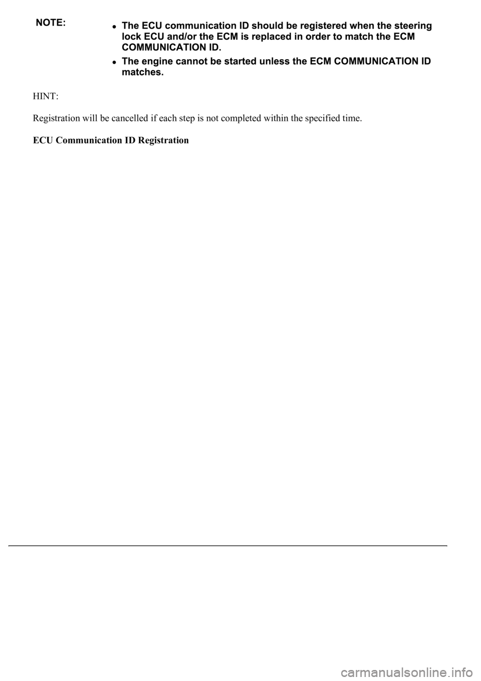
HINT:
Registration will be cancelled if each step is not completed within the specified time.
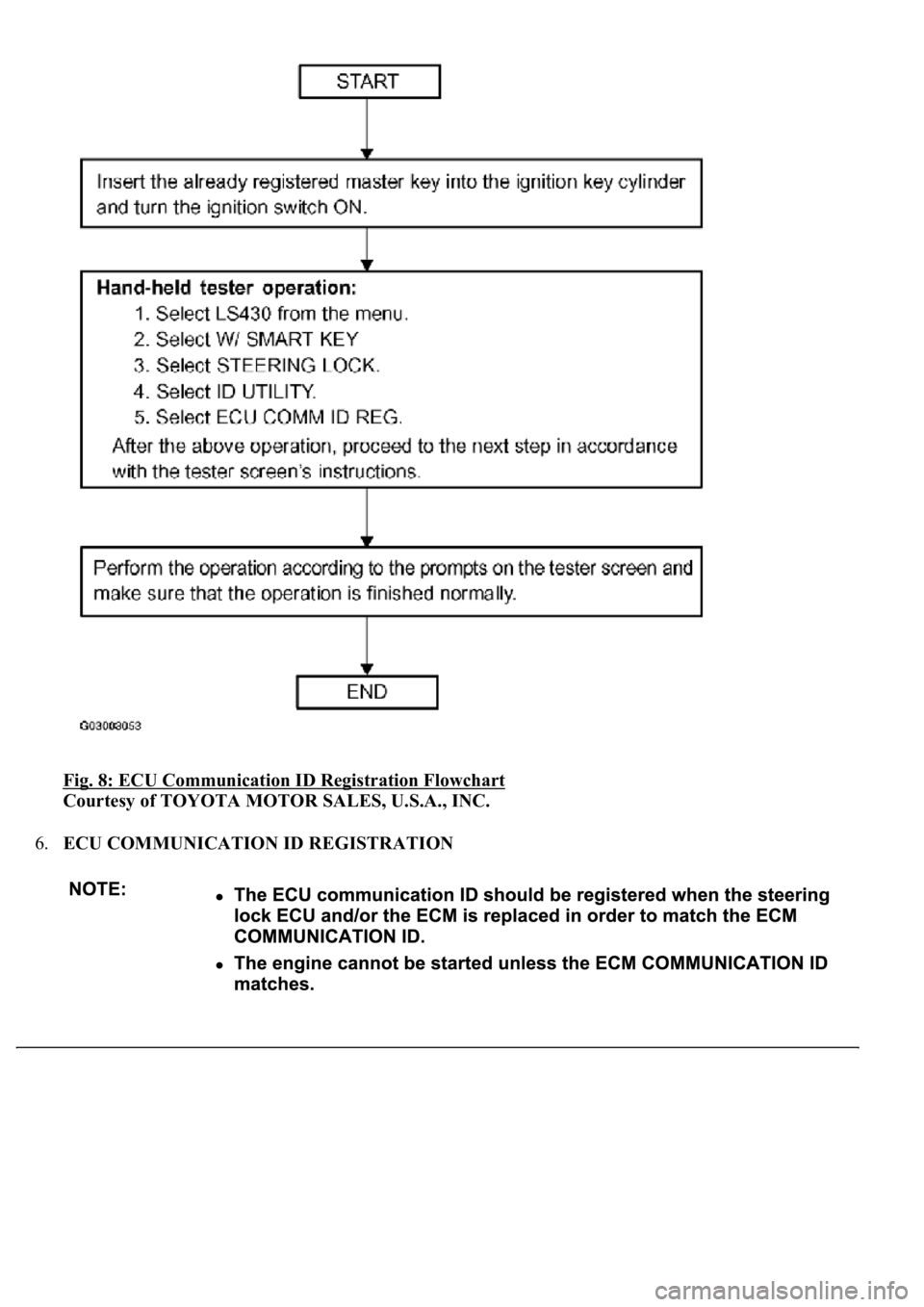
ECU Communication ID Registration
Page 3178 of 4500
Fig. 8: ECU Communication ID Registration Flowchart
Courtesy of TOYOTA MOTOR SALES, U.S.A., INC.
6.ECU COMMUNICATION ID REGISTRATION
Page 3179 of 4500
a. Register the ECU communication ID.
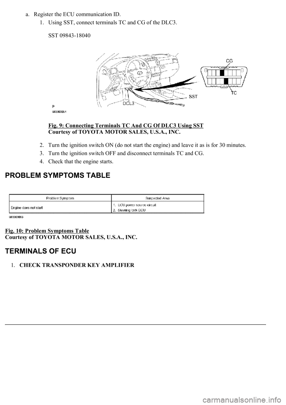
1. Using SST, connect terminals TC and CG of the DLC3.
SST 09843-18040
Fig. 9: Connecting Terminals TC And CG Of DLC3 Using SST
Courtesy of TOYOTA MOTOR SALES, U.S.A., INC.
2. Turn the ignition switch ON (do not start the engine) and leave it as is for 30 minutes.
3. Turn the ignition switch OFF and disconnect terminals TC and CG.
4. Check that the engine starts.
Fig. 10: Problem Symptoms Table
Courtesy of TOYOTA MOTOR SALES, U.S.A., INC.
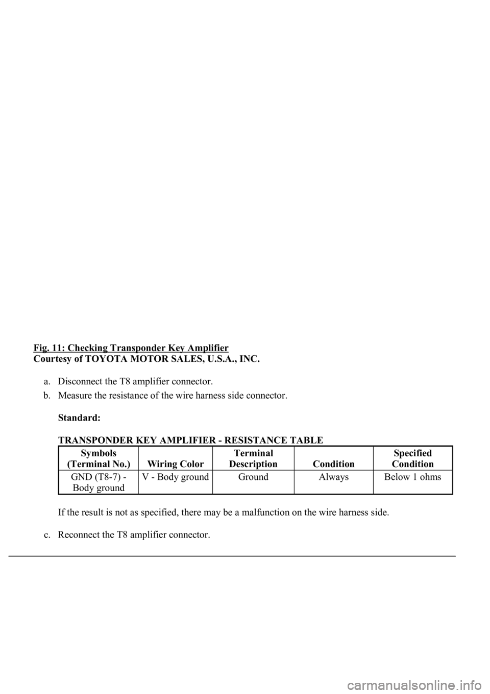
1.CHECK TRANSPONDER KEY AMPLIFIER
Page 3180 of 4500
Fig. 11: Checking Transponder Key Amplifier
Courtesy of TOYOTA MOTOR SALES, U.S.A., INC.
a. Disconnect the T8 amplifier connector.
b. Measure the resistance of the wire harness side connector.
Standard:
TRANSPONDER KEY AMPLIFIER - RESISTANCE TABLE
If the result is not as specified, there may be a malfunction on the wire harness side.
c. Reconnect the T8 amplifier connector.
Symbols
(Terminal No.)
Wiring Color
Terminal
Description
Condition
Specified
Condition
GND (T8-7) -
Body groundV - Body groundGroundAlwaysBelow 1 ohms
Trending: battery location, reset, warning light, height, ESP, Bean, lights

