LEXUS LS430 2003 Factory Repair Manual
Manufacturer: LEXUS, Model Year: 2003,
Model line: LS430,
Model: LEXUS LS430 2003
Pages: 4500, PDF Size: 87.45 MB
LEXUS LS430 2003 Factory Repair Manual
LS430 2003
LEXUS
LEXUS
https://www.carmanualsonline.info/img/36/57050/w960_57050-0.png
LEXUS LS430 2003 Factory Repair Manual
Trending: odometer, radiator cap, power steering, clutch, fuses, service reset, Identifying ac
Page 3181 of 4500
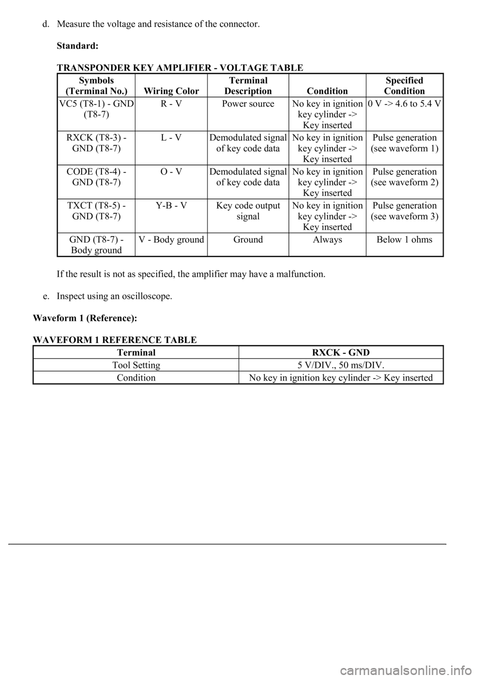
d. Measure the voltage and resistance of the connector.
Standard:
TRANSPONDER KEY AMPLIFIER - VOLTAGE TABLE
If the result is not as specified, the amplifier may have a malfunction.
e. Inspect using an oscilloscope.
Waveform 1 (Reference):
WAVEFORM 1 REFERENCE TABLE
Symbols
(Terminal No.)
Wiring Color
Terminal
Description
Condition
Specified
Condition
VC5 (T8-1) - GND
(T8-7)R - VPower sourceNo key in ignition
key cylinder ->
Key inserted0 V -> 4.6 to 5.4 V
RXCK (T8-3) -
GND (T8-7)L - VDemodulated signal
of key code dataNo key in ignition
key cylinder ->
Key insertedPulse generation
(see waveform 1)
CODE (T8-4) -
GND (T8-7)O - VDemodulated signal
of key code dataNo key in ignition
key cylinder ->
Key insertedPulse generation
(see waveform 2)
TXCT (T8-5) -
GND (T8-7)Y-B - VKey code output
signalNo key in ignition
key cylinder ->
Key insertedPulse generation
(see waveform 3)
GND (T8-7) -
Body groundV - Body groundGroundAlwaysBelow 1 ohms
TerminalRXCK - GND
Tool Setting5 V/DIV., 50 ms/DIV.
ConditionNo key in ignition key cylinder -> Key inserted
Page 3182 of 4500
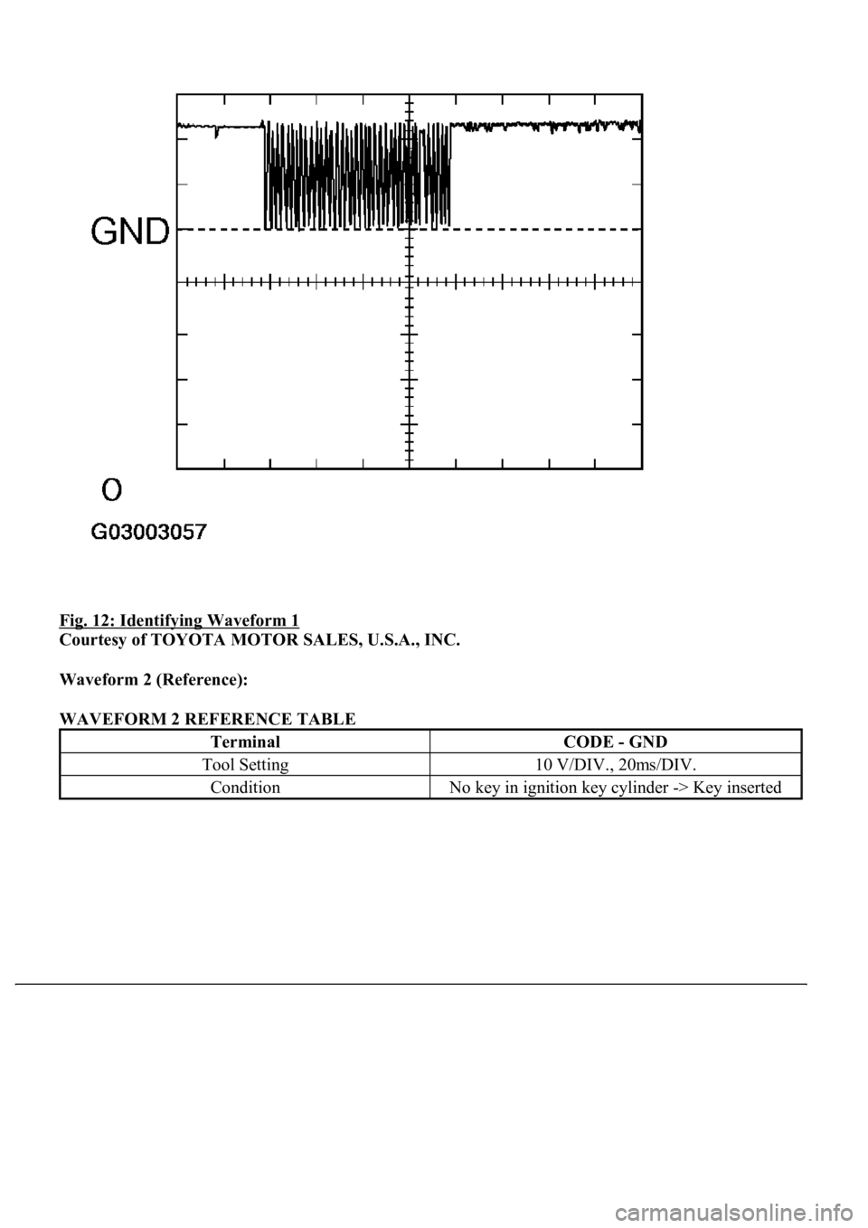
Fig. 12: Identifying Waveform 1
Courtesy of TOYOTA MOTOR SALES, U.S.A., INC.
Waveform 2 (Reference):
WAVEFORM 2 REFERENCE TABLE
TerminalCODE - GND
Tool Setting10 V/DIV., 20ms/DIV.
ConditionNo key in ignition key cylinder -> Key inserted
Page 3183 of 4500
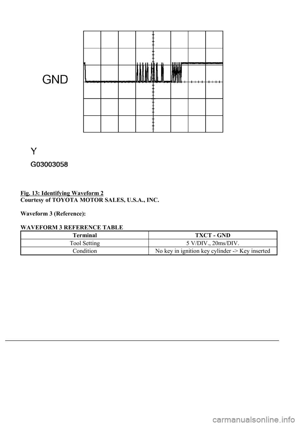
Fig. 13: Identifying Waveform 2
Courtesy of TOYOTA MOTOR SALES, U.S.A., INC.
Waveform 3 (Reference):
WAVEFORM 3 REFERENCE TABLE
TerminalTXCT - GND
Tool Setting5 V/DIV., 20ms/DIV.
ConditionNo key in ignition key cylinder -> Key inserted
Page 3184 of 4500
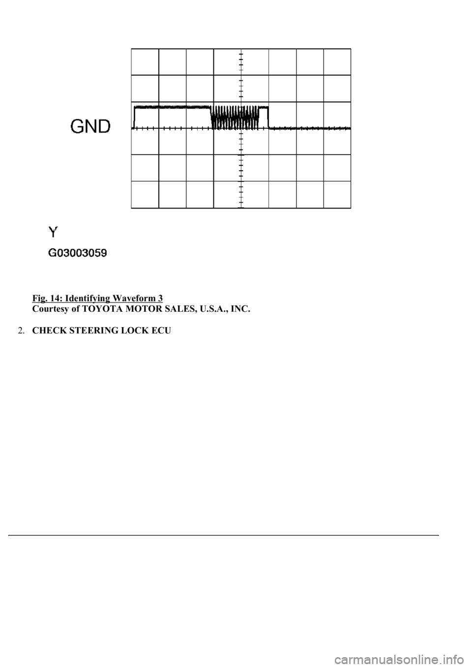
Fig. 14: Identifying Waveform 3
Courtesy of TOYOTA MOTOR SALES, U.S.A., INC.
2.CHECK STEERING LOCK ECU
Page 3185 of 4500
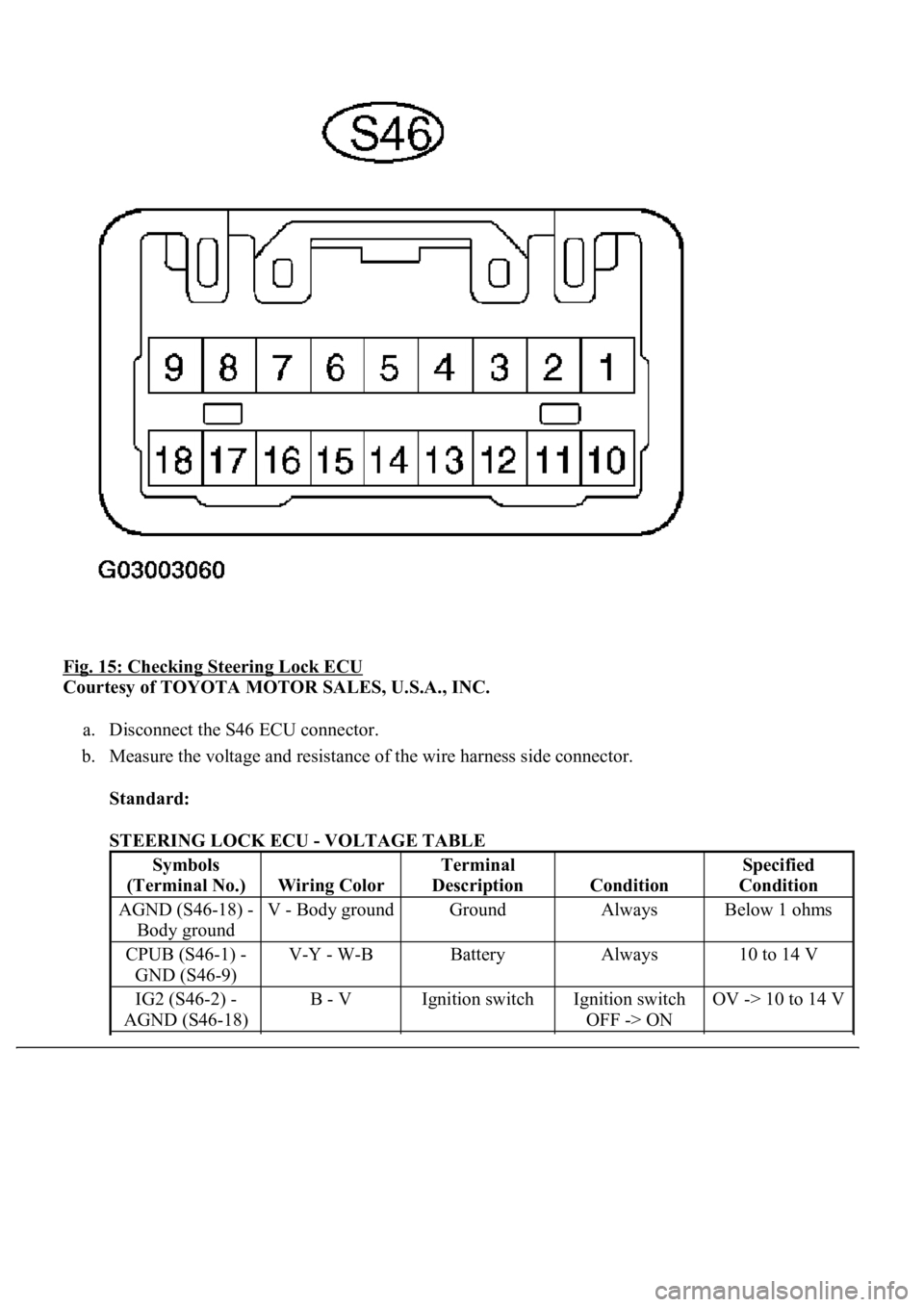
Fig. 15: Checking Steering Lock ECU
Courtesy of TOYOTA MOTOR SALES, U.S.A., INC.
a. Disconnect the S46 ECU connector.
b. Measure the voltage and resistance of the wire harness side connector.
Standard:
STEERING LOCK ECU - VOLTAGE TABLE
Symbols
(Terminal No.)
Wiring Color
Terminal
Description
Condition
Specified
Condition
AGND (S46-18) -
Body groundV - Body groundGroundAlwaysBelow 1 ohms
CPUB (S46-1) -
GND (S46-9)V-Y - W-BBatteryAlways10 to 14 V
IG2 (S46-2) -
AGND (S46-18)B - VIgnition switchIgnition switch
OFF -> ONOV -> 10 to 14 V
Page 3186 of 4500
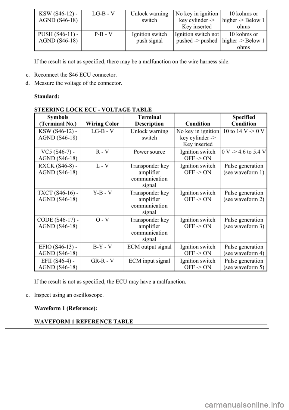
If the result is not as specified, there may be a malfunction on the wire harness side.
c. Reconnect the S46 ECU connector.
d. Measure the voltage of the connector.
Standard:
STEERING LOCK ECU - VOLTAGE TABLE
If the result is not as specified, the ECU may have a malfunction.
e. Inspect using an oscilloscope.
Waveform 1 (Reference):
WAVEFORM 1 REFERENCE TABLE
KSW (S46-12) -
AGND (S46-18)LG-B - VUnlock warning
switchNo key in ignition
key cylinder ->
Key inserted10 kohms or
higher -> Below 1
ohms
PUSH (S46-11) -
AGND (S46-18)P-B - VIgnition switch
push signalIgnition switch not
pushed -> pushed10 kohms or
higher -> Below 1
ohms
Symbols
(Terminal No.)
Wiring Color
Terminal
Description
Condition
Specified
Condition
KSW (S46-12) -
AGND (S46-18)LG-B - VUnlock warning
switchNo key in ignition
key cylinder ->
Key inserted10 to 14 V -> 0 V
VC5 (S46-7) -
AGND (S46-18)R - VPower sourceIgnition switch
OFF -> ON0 V -> 4.6 to 5.4 V
RXCK (S46-8) -
AGND (S46-18)L - VTransponder key
amplifier
communication
signalIgnition switch
OFF -> ONPulse generation
(see waveform 1)
TXCT (S46-16) -
AGND (S46-18)Y-B - VTransponder key
amplifier
communication
signalIgnition switch
OFF -> ONPulse generation
(see waveform 2)
CODE (S46-17) -
AGND (S46-18)O - VTransponder key
amplifier
communication
signalIgnition switch
OFF -> ONPulse generation
(see waveform 3)
EFIO (S46-13) -
AGND (S46-18)B-Y - VECM output signalIgnition switch
OFF -> ONPulse generation
(see waveform 4)
EFII (S46-4) -
AGND (S46-18)GR-R - VECM input signalIgnition switch
OFF -> ONPulse generation
(see waveform 5)
Page 3187 of 4500
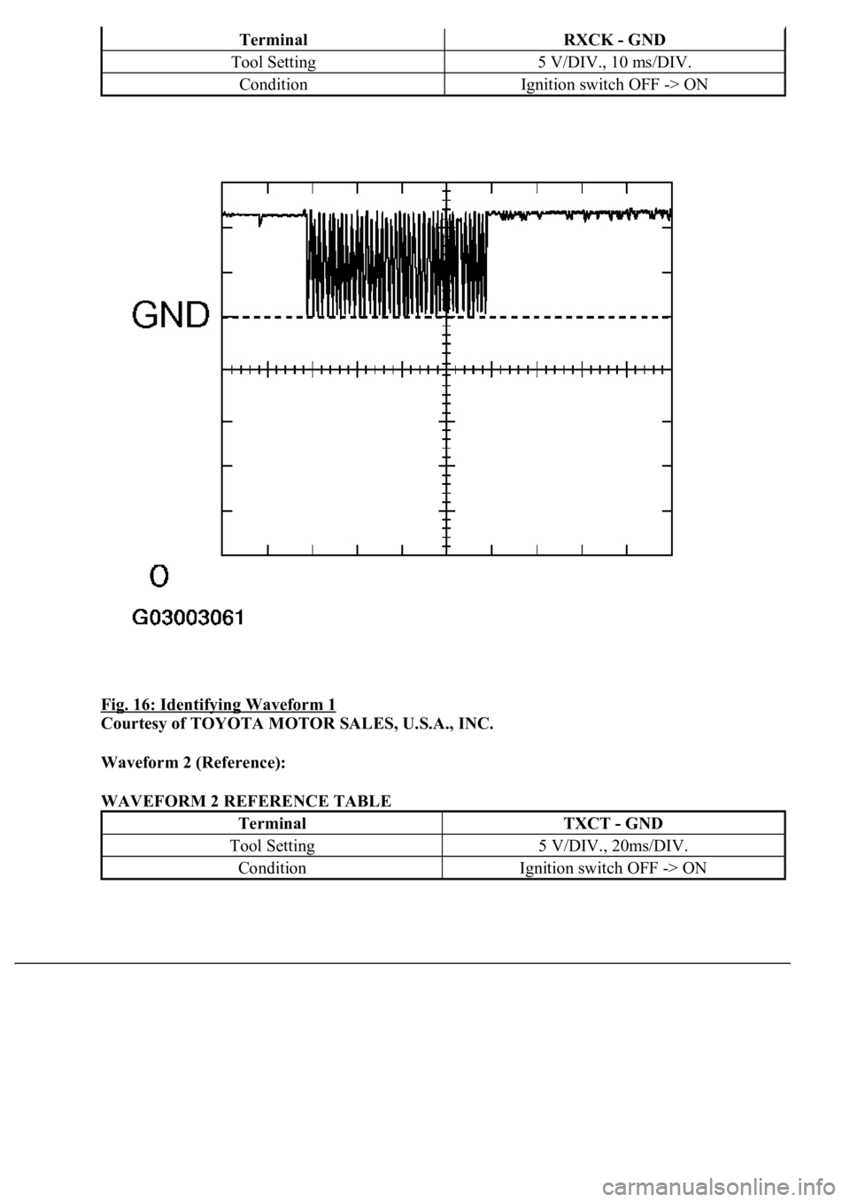
Fig. 16: Identifying Waveform 1
Courtesy of TOYOTA MOTOR SALES, U.S.A., INC.
Waveform 2 (Reference):
WAVEFORM 2 REFERENCE TABLE
TerminalRXCK - GND
Tool Setting5 V/DIV., 10 ms/DIV.
ConditionIgnition switch OFF -> ON
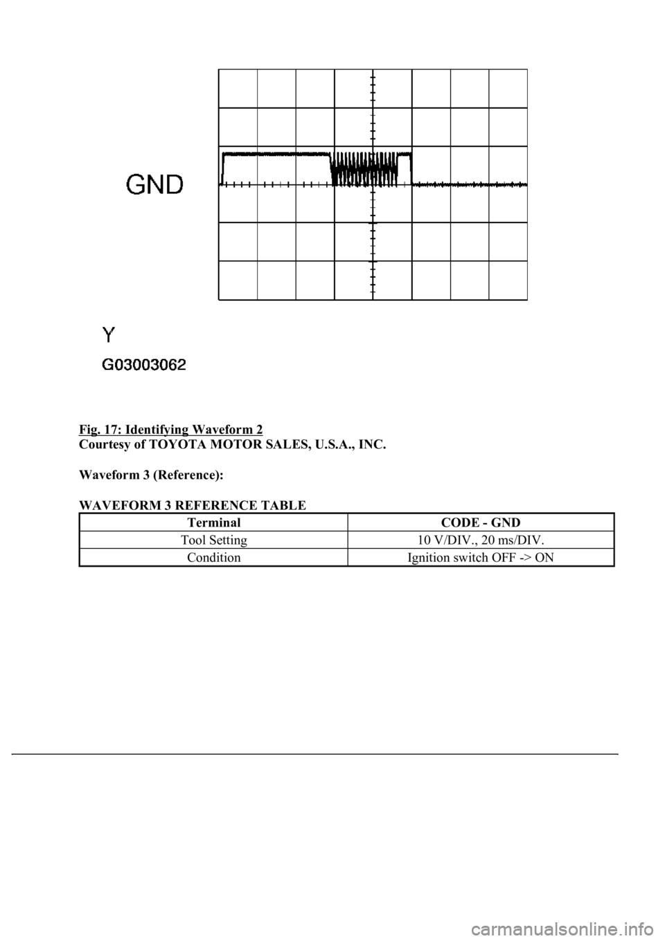
TerminalTXCT - GND
Tool Setting5 V/DIV., 20ms/DIV.
ConditionIgnition switch OFF -> ON
Page 3188 of 4500
Fig. 17: Identifying Waveform 2
Courtesy of TOYOTA MOTOR SALES, U.S.A., INC.
Waveform 3 (Reference):
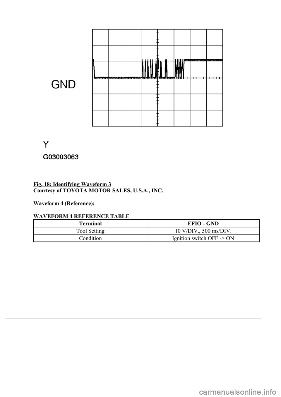
WAVEFORM 3 REFERENCE TABLE
TerminalCODE - GND
Tool Setting10 V/DIV., 20 ms/DIV.
ConditionIgnition switch OFF -> ON
Page 3189 of 4500
Fig. 18: Identifying Waveform 3
Courtesy of TOYOTA MOTOR SALES, U.S.A., INC.
Waveform 4 (Reference):
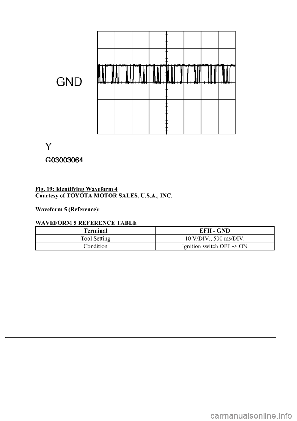
WAVEFORM 4 REFERENCE TABLE
TerminalEFIO - GND
Tool Setting10 V/DIV., 500 ms/DIV.
ConditionIgnition switch OFF -> ON
Page 3190 of 4500
Fig. 19: Identifying Waveform 4
Courtesy of TOYOTA MOTOR SALES, U.S.A., INC.
Waveform 5 (Reference):
WAVEFORM 5 REFERENCE TABLE
TerminalEFII - GND
Tool Setting10 V/DIV., 500 ms/DIV.
ConditionIgnition switch OFF -> ON
Trending: coolant reservoir, snow chains, brake, automatic transmission, torque, ad blue, height adjustment

