LEXUS LS430 2003 Factory Repair Manual
Manufacturer: LEXUS, Model Year: 2003,
Model line: LS430,
Model: LEXUS LS430 2003
Pages: 4500, PDF Size: 87.45 MB
LEXUS LS430 2003 Factory Repair Manual
LS430 2003
LEXUS
LEXUS
https://www.carmanualsonline.info/img/36/57050/w960_57050-0.png
LEXUS LS430 2003 Factory Repair Manual
Trending: Suspension control, check engine, child lock, tire pressure, c1751, zero point calibration, fuse box
Page 3421 of 4500
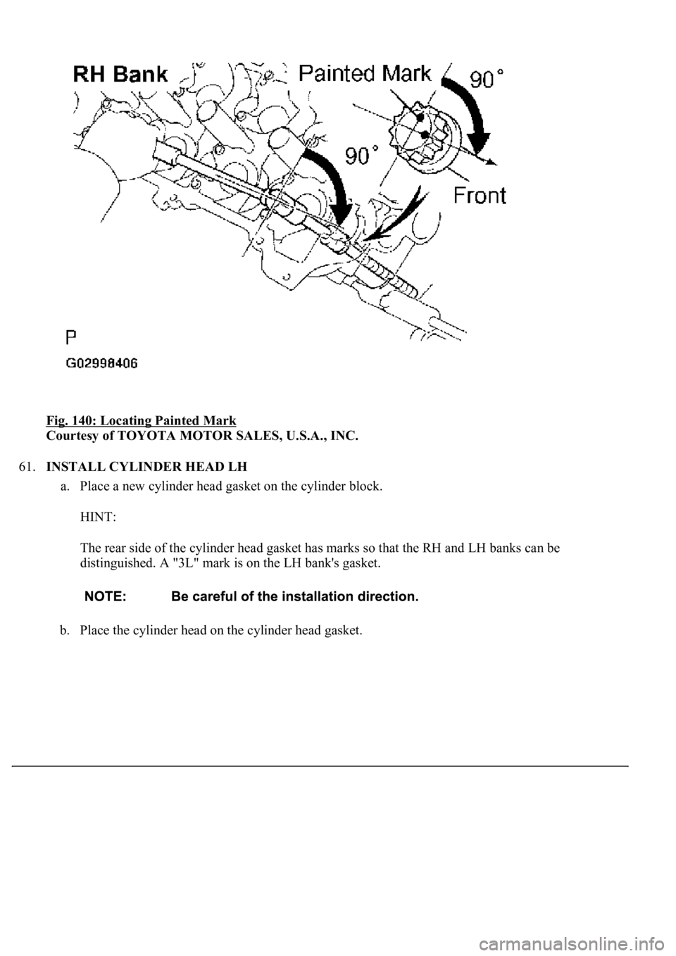
Fig. 140: Locating Painted Mark
Courtesy of TOYOTA MOTOR SALES, U.S.A., INC.
61.INSTALL CYLINDER HEAD LH
a. Place a new cylinder head gasket on the cylinder block.
HINT:
The rear side of the cylinder head gasket has marks so that the RH and LH banks can be
distinguished. A "3L" mark is on the LH bank's gasket.
b. Place the cylinder head on the cylinder head gasket.
Page 3422 of 4500
Fig. 141: Placing Cylinder Head On Cylinder Head Gasket
Courtesy of TOYOTA MOTOR SALES, U.S.A., INC.
c. Install the cylinder head bolts.
HINT:
The cylinder head bolts are tightened in 2 progressive steps (steps (3) and (5)).
If any cylinder head bolt is broken or deformed, replace it.
1. Apply a light coat of engine oil on the threads and under the heads of the cylinder head bolts.
2. Install the plate washer to the cylinder head bolt.
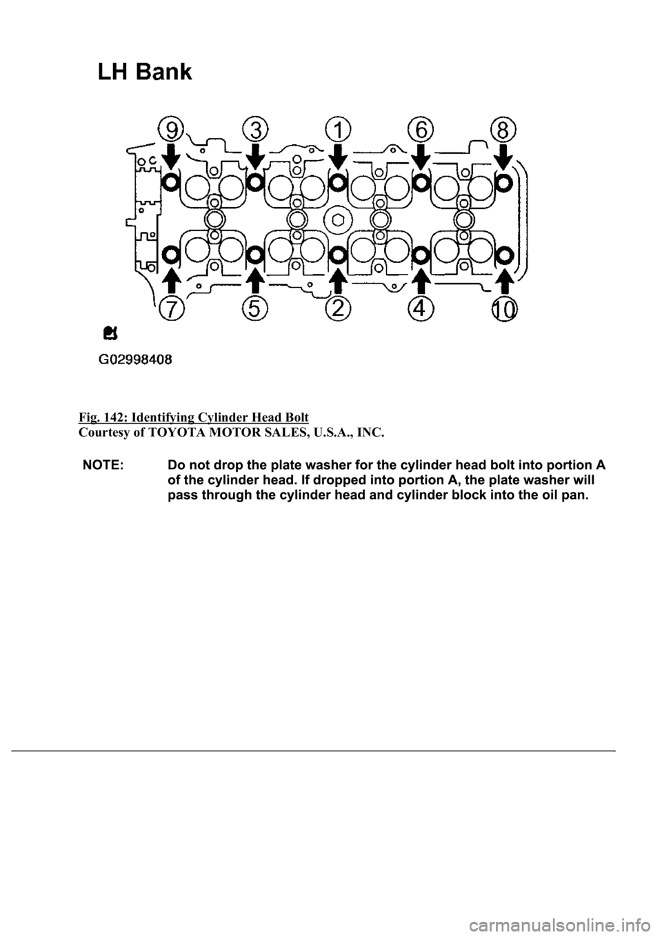
3. Install and uniformly tighten the 10 cylinder head bolts on one side of the cylinder head in several
passes in the sequence shown in the illustration.
Torque: 59 N.m (602 kgf.cm, 44 ft.lbf)
If any one of the cylinder head bolts does not meet the torque specification, replace the cylinder
head bolt.
Page 3423 of 4500
Fig. 142: Identifying Cylinder Head Bolt
Courtesy of TOYOTA MOTOR SALES, U.S.A., INC.
Page 3424 of 4500
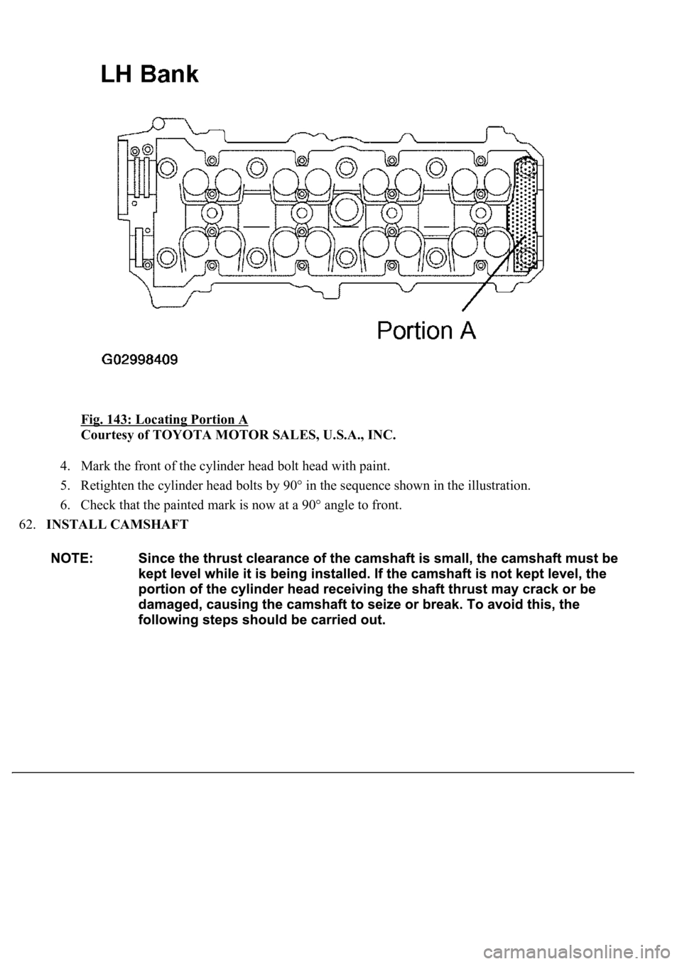
Fig. 143: Locating Portion A
Courtesy of TOYOTA MOTOR SALES, U.S.A., INC.
4. Mark the front of the cylinder head bolt head with paint.
5. Retighten the cylinder head bolts by 90° in the sequence shown in the illustration.
6. Check that the painted mark is now at a 90° angle to front.
62.INSTALL CAMSHAFT
Page 3425 of 4500
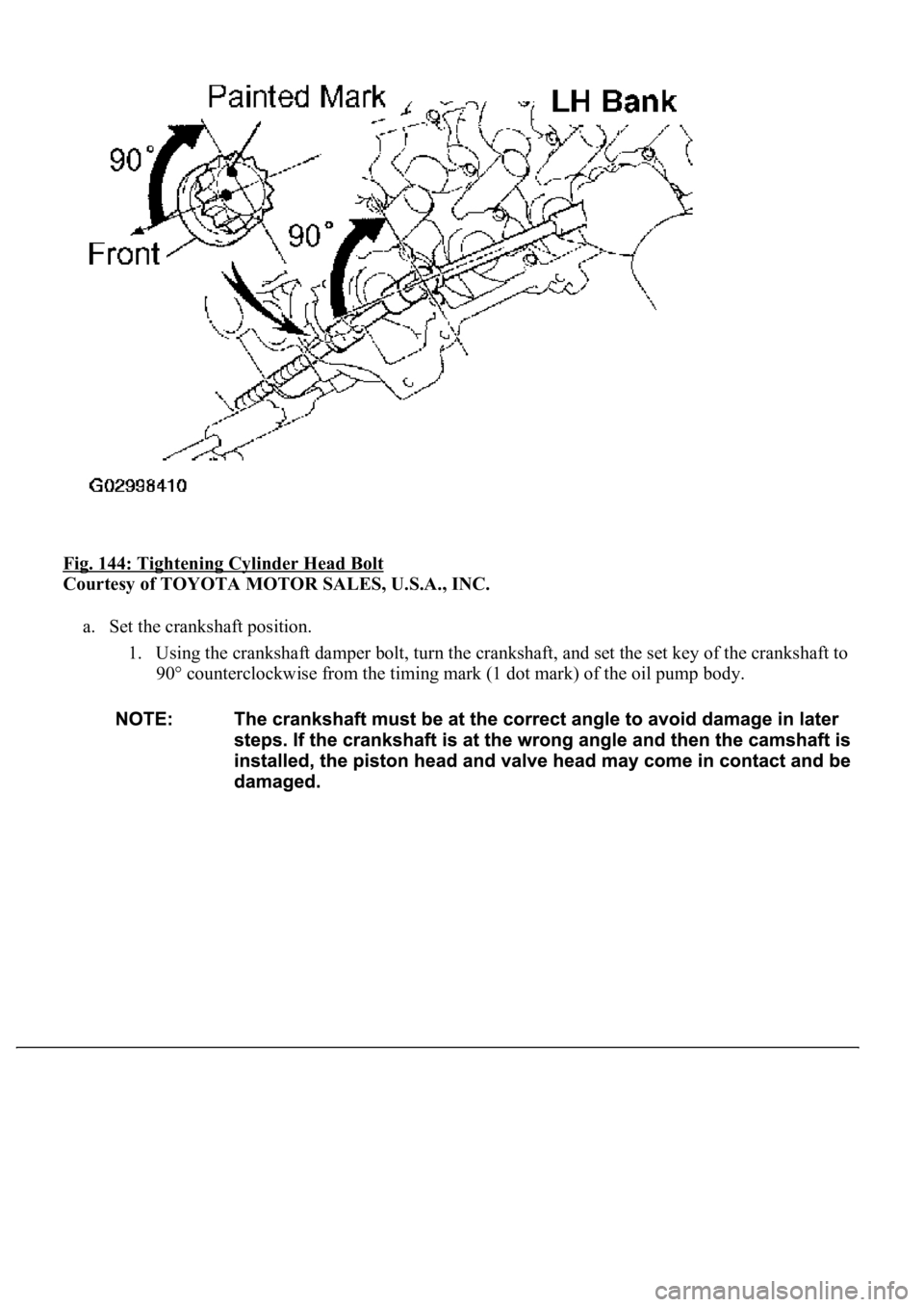
Fig. 144: Tightening Cylinder Head Bolt
Courtesy of TOYOTA MOTOR SALES, U.S.A., INC.
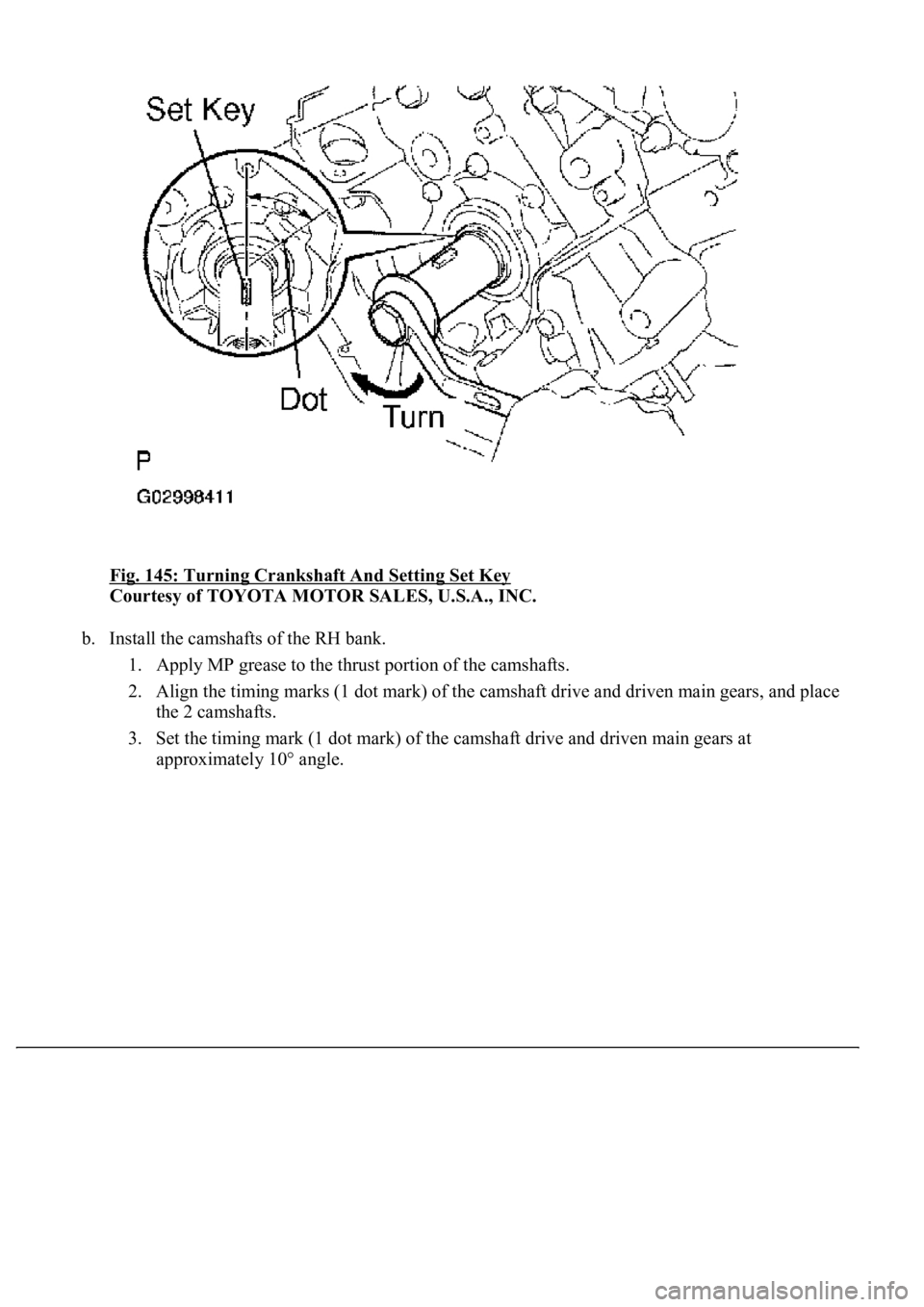
a. Set the crankshaft position.
1. Using the crankshaft damper bolt, turn the crankshaft, and set the set key of the crankshaft to
90° counterclockwise from the timing mark (1 dot mark) of the oil pump body.
Page 3426 of 4500
Fig. 145: Turning Crankshaft And Setting Set Key
Courtesy of TOYOTA MOTOR SALES, U.S.A., INC.
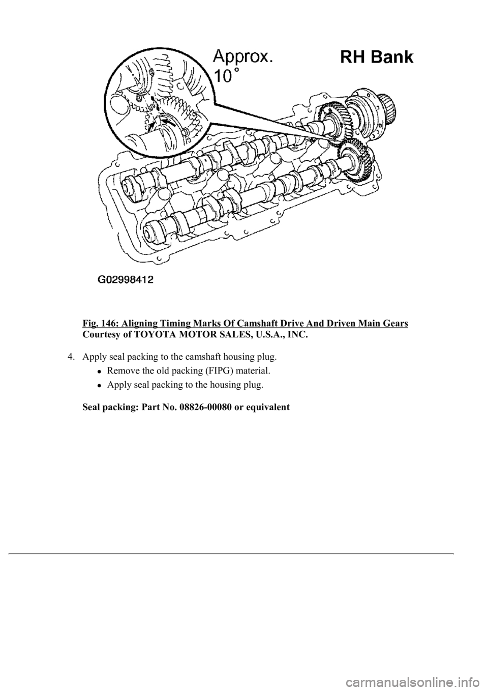
b. Install the camshafts of the RH bank.
1. Apply MP grease to the thrust portion of the camshafts.
2. Align the timing marks (1 dot mark) of the camshaft drive and driven main gears, and place
the 2 camshafts.
3. Set the timing mark (1 dot mark) of the camshaft drive and driven main gears at
approximatel
y 10° angle.
Page 3427 of 4500
Fig. 146: Aligning Timing Marks Of Camshaft Drive And Driven Main Gears
Courtesy of TOYOTA MOTOR SALES, U.S.A., INC.
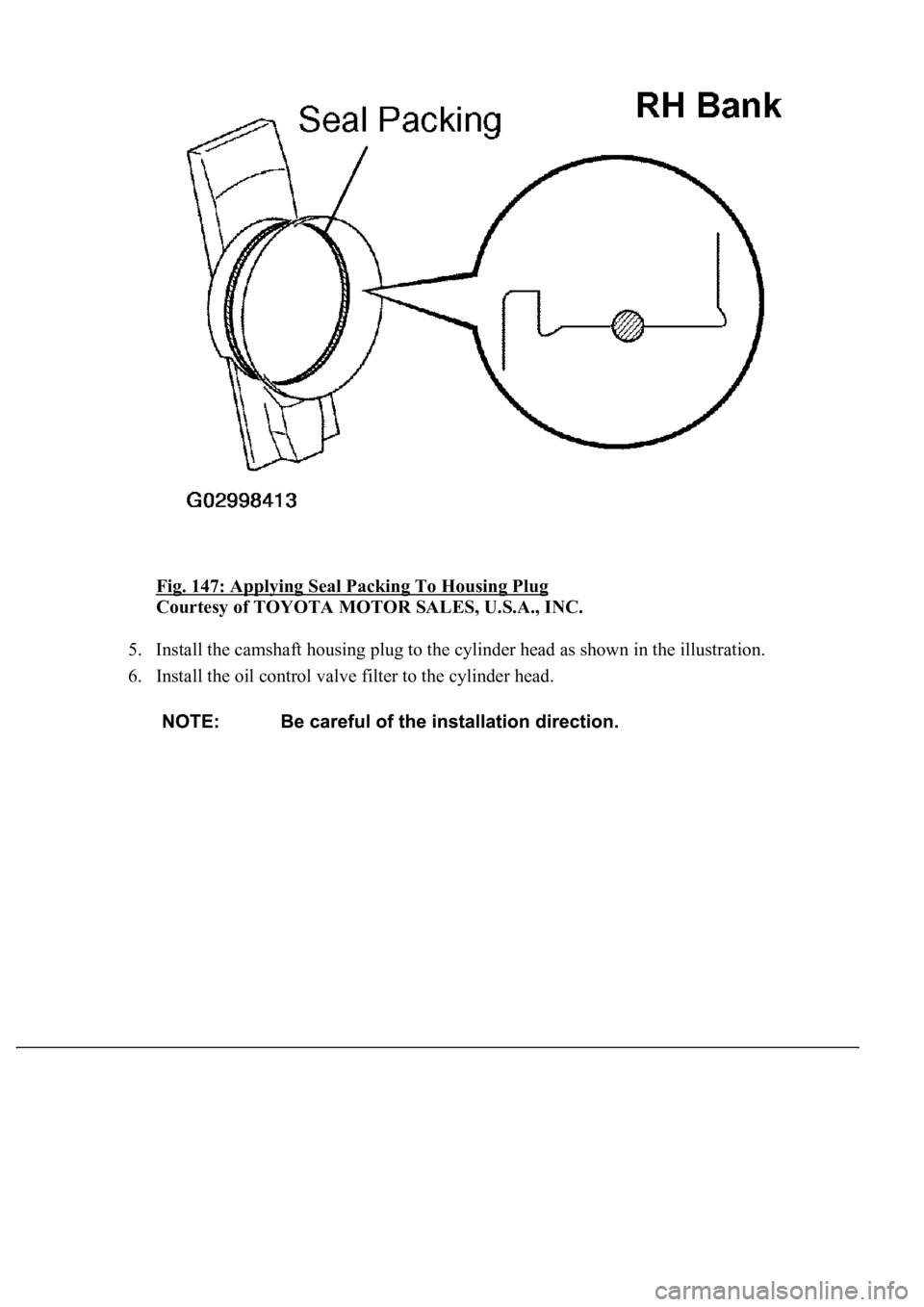
4. Apply seal packing to the camshaft housing plug.
Remove the old packing (FIPG) material.
Apply seal packing to the housing plug.
Seal packing: Part No. 08826-00080 or equivalent
Page 3428 of 4500
Fig. 147: Applying Seal Packing To Housing Plug
Courtesy of TOYOTA MOTOR SALES, U.S.A., INC.
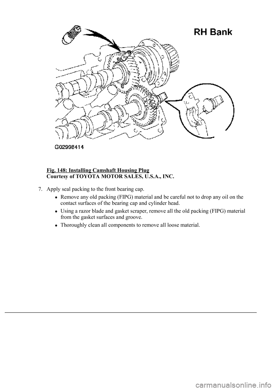
5. Install the camshaft housing plug to the cylinder head as shown in the illustration.
6. Install the oil control valve filter to the cylinder head.
Page 3429 of 4500
Fig. 148: Installing Camshaft Housing Plug
Courtesy of TOYOTA MOTOR SALES, U.S.A., INC.
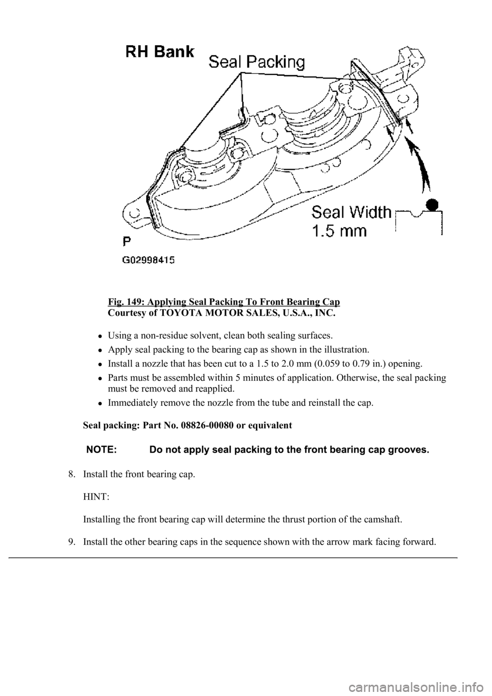
7. Apply seal packing to the front bearing cap.
Remove any old packing (FIPG) material and be careful not to drop any oil on the
contact surfaces of the bearing cap and cylinder head.
Using a razor blade and gasket scraper, remove all the old packing (FIPG) material
from the gasket surfaces and groove.
Thoroughly clean all components to remove all loose material.
Page 3430 of 4500
Fig. 149: Applying Seal Packing To Front Bearing Cap
Courtesy of TOYOTA MOTOR SALES, U.S.A., INC.
Using a non-residue solvent, clean both sealing surfaces.
Apply seal packing to the bearing cap as shown in the illustration.
Install a nozzle that has been cut to a 1.5 to 2.0 mm (0.059 to 0.79 in.) opening.
Parts must be assembled within 5 minutes of application. Otherwise, the seal packing
must be removed and reapplied.
Immediately remove the nozzle from the tube and reinstall the cap.
Seal packing: Part No. 08826-00080 or equivalent
8. Install the front bearing cap.
HINT:
Installing the front bearing cap will determine the thrust portion of the camshaft.
9. Install the other bearing caps in the sequence shown with the arrow mark facing forward.
Trending: valve assy, brakes, climate control, timing belt, seat adjustment, drain bolt, lights
