LEXUS LS430 2003 Factory Repair Manual
Manufacturer: LEXUS, Model Year: 2003,
Model line: LS430,
Model: LEXUS LS430 2003
Pages: 4500, PDF Size: 87.45 MB
LEXUS LS430 2003 Factory Repair Manual
LS430 2003
LEXUS
LEXUS
https://www.carmanualsonline.info/img/36/57050/w960_57050-0.png
LEXUS LS430 2003 Factory Repair Manual
Trending: boot, adding oil, ECO mode, headrest, height adjustment, head, Lock actuator
Page 3461 of 4500
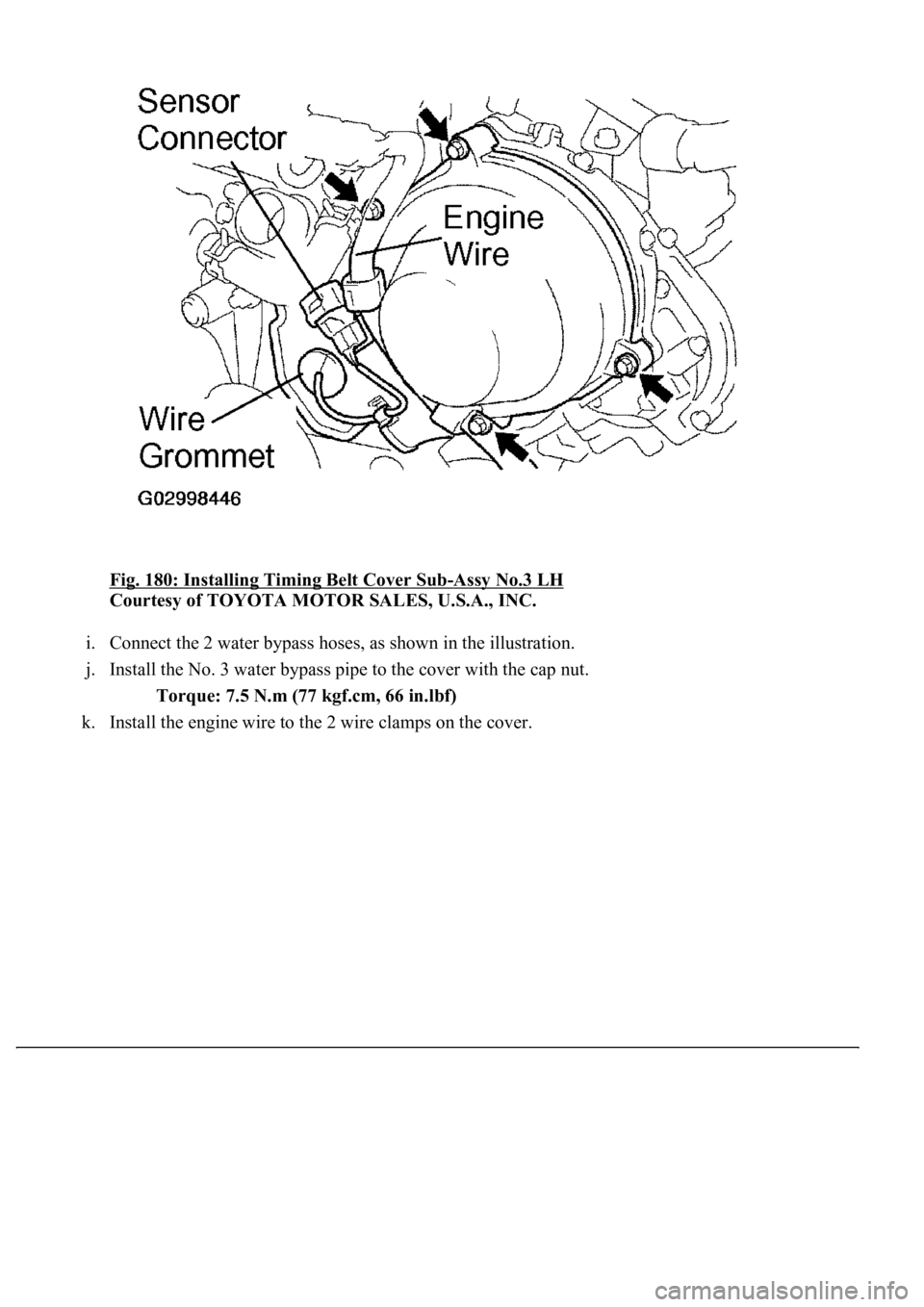
Fig. 180: Installing Timing Belt Cover Sub-Assy No.3 LH
Courtesy of TOYOTA MOTOR SALES, U.S.A., INC.
i. Connect the 2 water bypass hoses, as shown in the illustration.
j. Install the No. 3 water bypass pipe to the cover with the cap nut.
Torque: 7.5 N.m (77 kgf.cm, 66 in.lbf)
k. Install the en
gine wire to the 2 wire clamps on the cover.
Page 3462 of 4500
Fig. 181: Connecting Water By-Pass Hoses
Courtesy of TOYOTA MOTOR SALES, U.S.A., INC.
84.INSTALL TIMING CHAIN OR BELT COVER NO.2
a. Install the gasket to the cover.
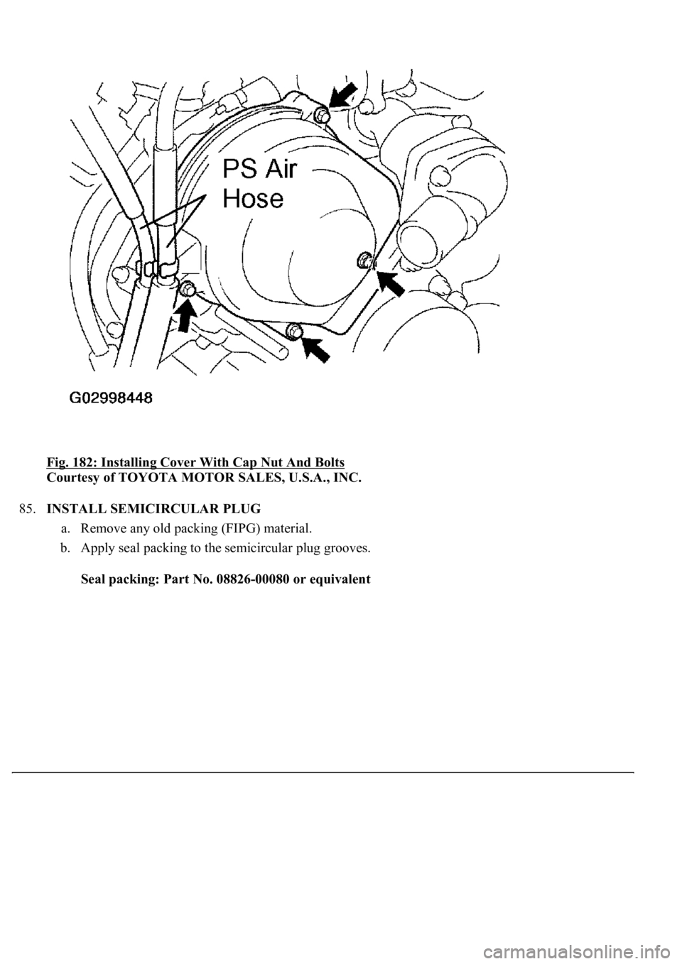
b. Install the cover with the cap nut and 3 bolts.
Torque: 7.5 N.m (77 kgf.cm, 66 in.lbf)
c. Install the 2 PS air hoses to the clamp on the cover.
Page 3463 of 4500
Fig. 182: Installing Cover With Cap Nut And Bolts
Courtesy of TOYOTA MOTOR SALES, U.S.A., INC.
85.INSTALL SEMICIRCULAR PLUG
a. Remove any old packing (FIPG) material.
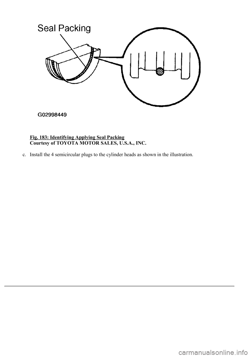
b. Apply seal packing to the semicircular plug grooves.
Seal packing: Part No. 08826-00080 or equivalent
Page 3464 of 4500
Fig. 183: Identifying Applying Seal Packing
Courtesy of TOYOTA MOTOR SALES, U.S.A., INC.
c. Install the 4 semicircular plugs to the cylinder heads as shown in the illustration.
Page 3465 of 4500
Fig. 184: Identifying Cylinder Heads
Page 3466 of 4500
Courtesy of TOYOTA MOTOR SALES, U.S.A., INC.
86.INSTALL CYLINDER HEAD COVER SUB-ASSY
a. Remove any old packing (FIPG) material.
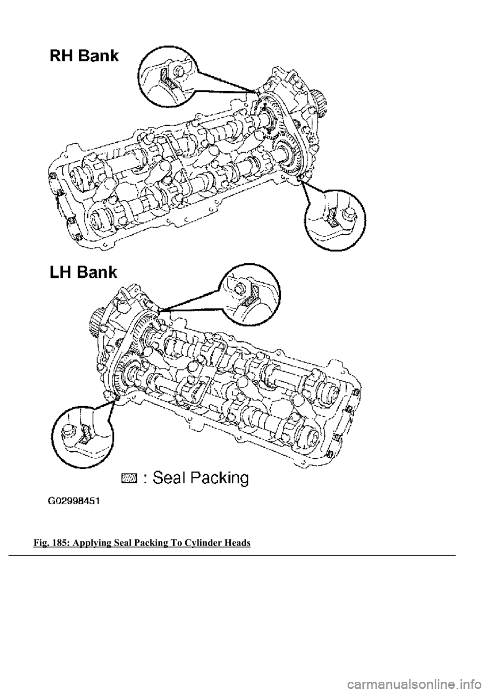
b. Apply seal packing to the cylinder heads as shown in the illustration.
Seal packing: Part No. 08826-00080 or equivalent
c. Install the gasket to the cylinder head cover.
d. Install the seal washer to the bolt.
e. Install the cylinder head cover with the 9 bolts. Uniformly tighten the bolts in several passes.
Torque: 6.0 N.m (61 kgf.cm, 53 in.lbf)
Page 3467 of 4500
Fig. 185: Applying Seal Packing To Cylinder Heads
Page 3468 of 4500
Courtesy of TOYOTA MOTOR SALES, U.S.A., INC.
87.INSTALL OIL FILLER CAP SUB-ASSY
88.INSTALL SPARK PLUG
REPLACEMENT
1.DISCONNECT BATTERY NEGATIVE TERMINAL
2.REMOVE AIR CLEANER INLET NO.1
3.DRAIN ENGINE COOLANT
4.REMOVE V-BANK COVER
5.REMOVE INTAKE AIR CONNECTOR PIPE
6.REMOVE ENGINE UNDER COVER NO.1
7.DISCONNECT RADIATOR HOSE NO.1
8.DISCONNECT RADIATOR HOSE NO.2
9.DISCONNECT OIL COOLER INLET TUBE NO.1
10.DISCONNECT OIL COOLER OUTLET TUBE NO.1
11.REMOVE AIR CLEANER ASSY
12.REMOVE RADIATOR ASSY (See REPLACEMENT
13.REMOVE FAN AND GENERATOR V BELT (See REPLACEMENT
)
14.REMOVE VANE PUMP ASSY
a. Remove the 2 bolts, nut and pump.
HINT:
Pump should be removed with the hoses connected and then hang with a rope or wire on the body's side.
15.REMOVE GENERATOR ASSY (See REPLACEMENT
)
16.DISCONNECT COMPRESSOR AND MAGNETIC CLUTCH
HINT:
The cooler compressor with the magnetic clutch should be removed with the low-pressure and high-
pressure hoses connected and then hang with a rope or wire on the body's side.
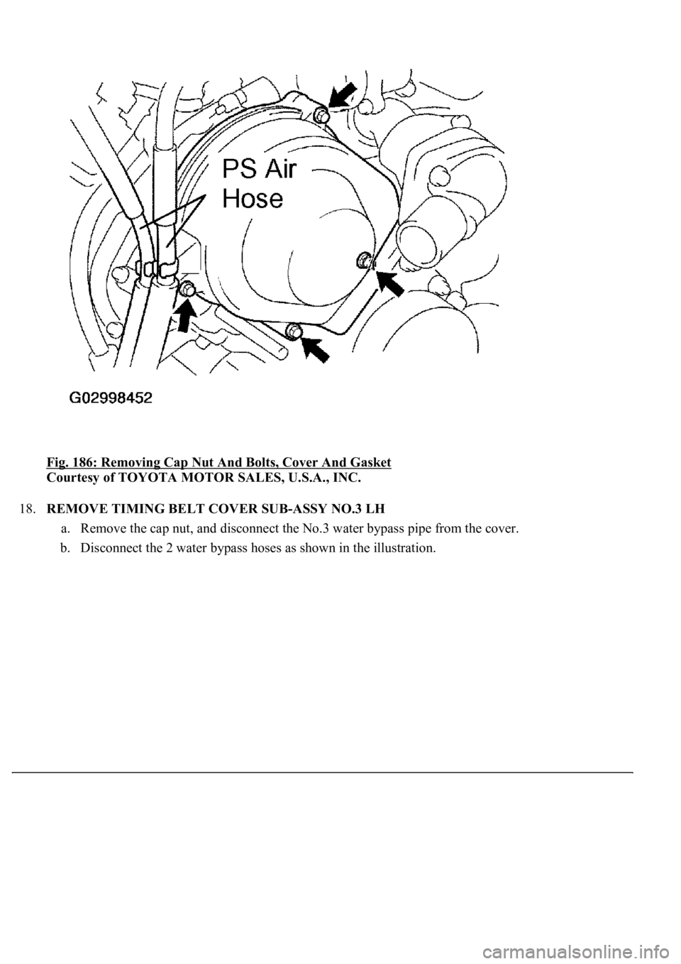
17.REMOVE TIMING CHAIN OR BELT COVER NO.2
a. Disconnect the 2 PS air hoses from the clamp on the cover.
b. Remove the cap nut, 3 bolts, cover and gasket.
Page 3469 of 4500
Fig. 186: Removing Cap Nut And Bolts, Cover And Gasket
Courtesy of TOYOTA MOTOR SALES, U.S.A., INC.
18.REMOVE TIMING BELT COVER SUB-ASSY NO.3 LH
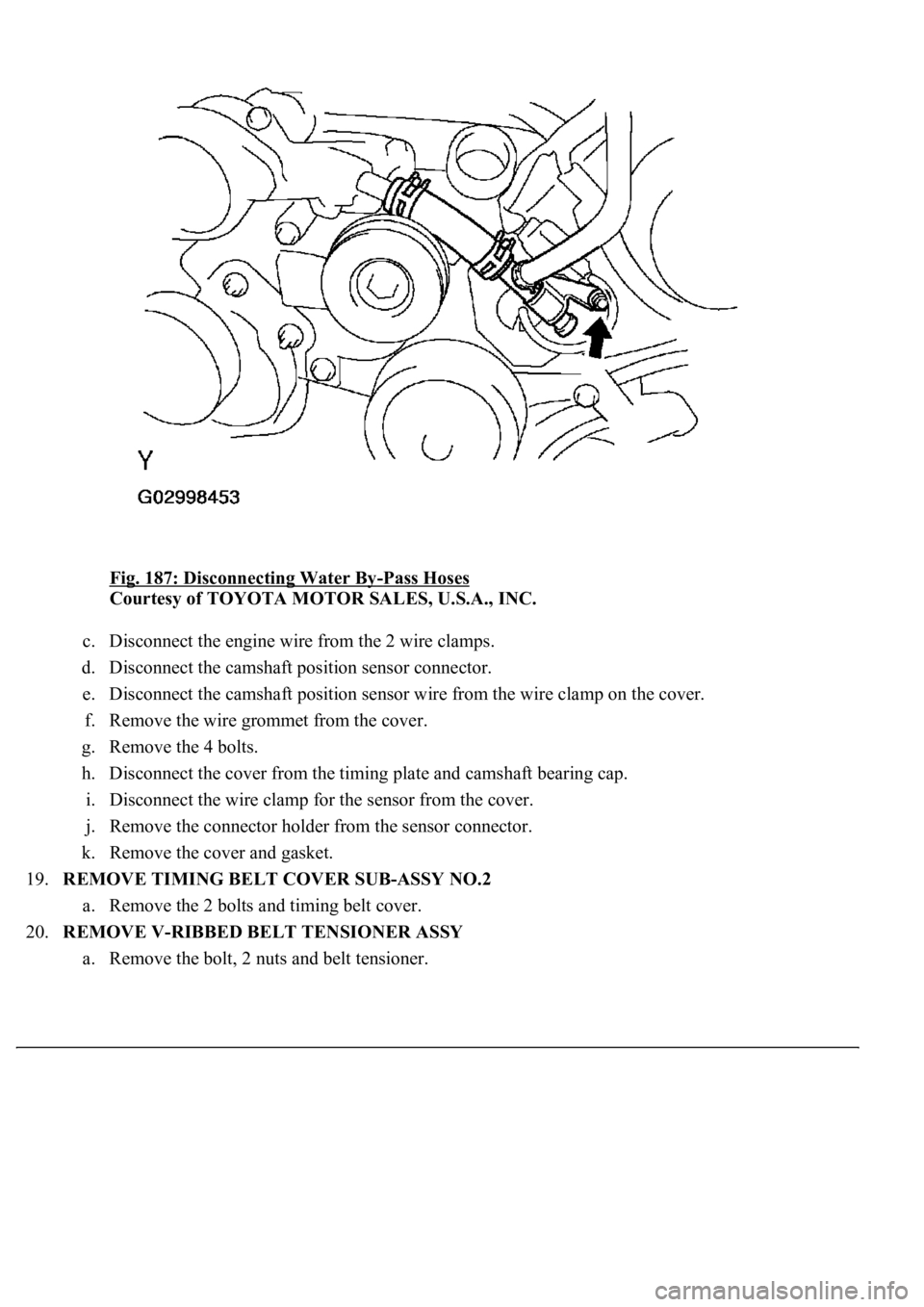
a. Remove the cap nut, and disconnect the No.3 water bypass pipe from the cover.
b. Disconnect the 2 water bypass hoses as shown in the illustration.
Page 3470 of 4500
Fig. 187: Disconnecting Water By-Pass Hoses
Courtesy of TOYOTA MOTOR SALES, U.S.A., INC.
c. Disconnect the engine wire from the 2 wire clamps.
d. Disconnect the camshaft position sensor connector.
e. Disconnect the camshaft position sensor wire from the wire clamp on the cover.
f. Remove the wire grommet from the cover.
g. Remove the 4 bolts.
h. Disconnect the cover from the timing plate and camshaft bearing cap.
i. Disconnect the wire clamp for the sensor from the cover.
j. Remove the connector holder from the sensor connector.
k. Remove the cover and gasket.
19.REMOVE TIMING BELT COVER SUB-ASSY NO.2
a. Remove the 2 bolts and timing belt cover.
20.REMOVE V-RIBBED BELT TENSIONER ASSY
a. Remove the bolt, 2 nuts and belt tensioner.
Trending: B2799, diagram, c1751, fuel type, CD changer, evaporator removal, Combination
