LEXUS LS430 2003 Factory Repair Manual
Manufacturer: LEXUS, Model Year: 2003,
Model line: LS430,
Model: LEXUS LS430 2003
Pages: 4500, PDF Size: 87.45 MB
LEXUS LS430 2003 Factory Repair Manual
LS430 2003
LEXUS
LEXUS
https://www.carmanualsonline.info/img/36/57050/w960_57050-0.png
LEXUS LS430 2003 Factory Repair Manual
Trending: oxygen sensor, display, steering wheel adjustment, odometer, Spark plug, radiator cap, lights
Page 3431 of 4500
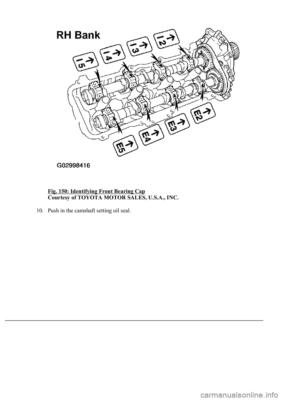
Fig. 150: Identifying Front Bearing Cap
Courtesy of TOYOTA MOTOR SALES, U.S.A., INC.
10. Push in the camshaft settin
g oil seal.
Page 3432 of 4500
Fig. 151: Pushing Camshaft Setting Oil Seal
Courtesy of TOYOTA MOTOR SALES, U.S.A., INC.
11. Install a new seal washer to the bearing cap bolts (A and B).
12. Apply a light coat of engine oil on the threads and under the heads of the bearing cap bolts
(D and E).
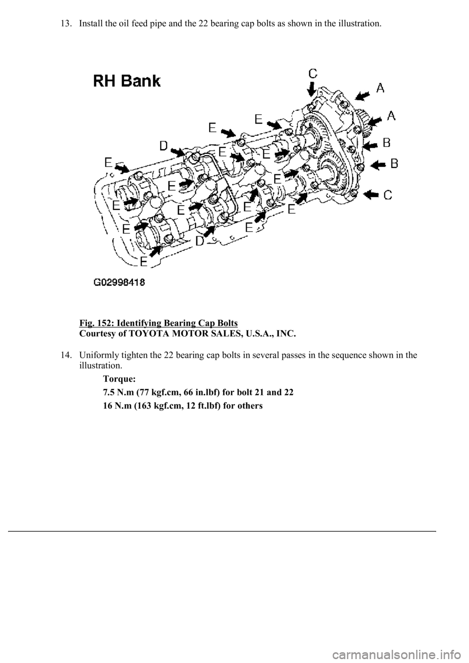
Bolt length:
94 mm (3.70 in.) for A with seal washer
72 mm (2.83 in.) for B with seal washer
25 mm (0.98 in.) for C
52 mm (2.05 in.) for D
38 mm (1.50 in.) for E
Page 3433 of 4500
13. Install the oil feed pipe and the 22 bearing cap bolts as shown in the illustration.
Fig. 152: Identifying Bearing Cap Bolts
Courtesy of TOYOTA MOTOR SALES, U.S.A., INC.
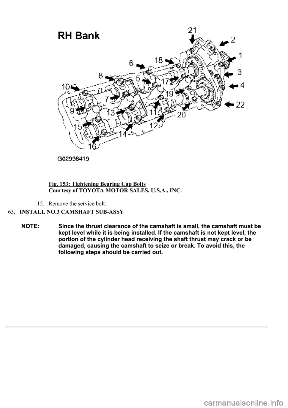
14. Uniformly tighten the 22 bearing cap bolts in several passes in the sequence shown in the
illustration.
Torque:
7.5 N.m (77 kgf.cm, 66 in.lbf) for bolt 21 and 22
16 N.m (163 kgf.cm, 12 ft.lbf) for others
Page 3434 of 4500
Fig. 153: Tightening Bearing Cap Bolts
Courtesy of TOYOTA MOTOR SALES, U.S.A., INC.
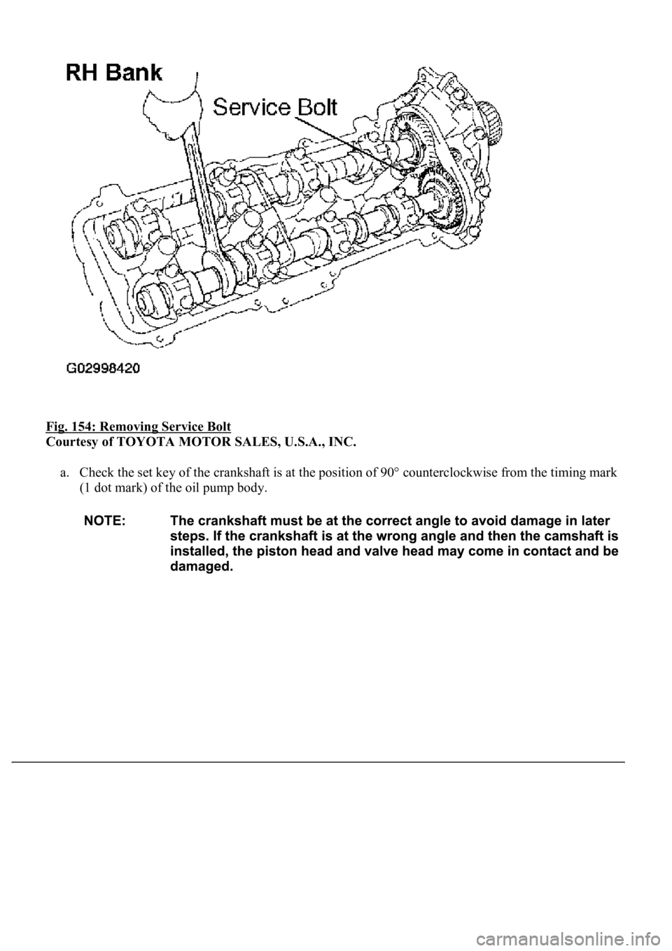
15. Remove the service bolt.
63.INSTALL NO.3 CAMSHAFT SUB-ASSY
Page 3435 of 4500
Fig. 154: Removing Service Bolt
Courtesy of TOYOTA MOTOR SALES, U.S.A., INC.
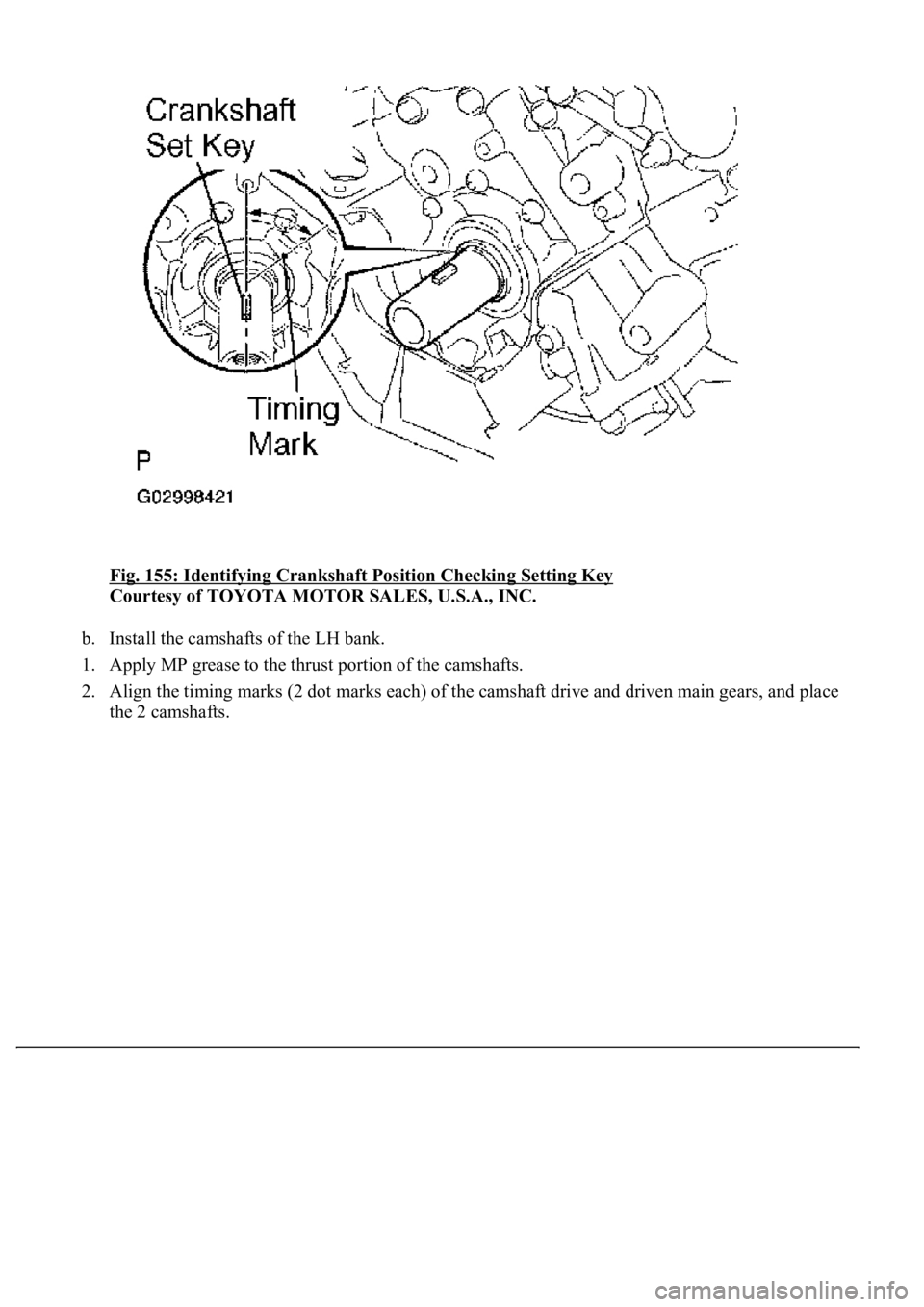
a. Check the set key of the crankshaft is at the position of 90° counterclockwise from the timing mark
(1 dot mark) of the oil pump body.
Page 3436 of 4500
Fig. 155: Identifying Crankshaft Position Checking Setting Key
Courtesy of TOYOTA MOTOR SALES, U.S.A., INC.
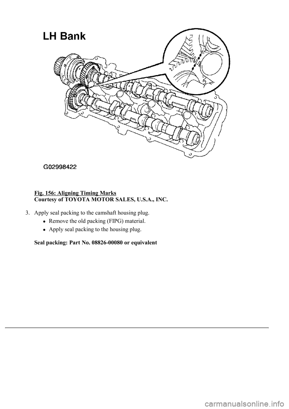
b. Install the camshafts of the LH bank.
1. Apply MP grease to the thrust portion of the camshafts.
2. Align the timing marks (2 dot marks each) of the camshaft drive and driven main gears, and place
the 2 camshafts.
Page 3437 of 4500
Fig. 156: Aligning Timing Marks
Courtesy of TOYOTA MOTOR SALES, U.S.A., INC.
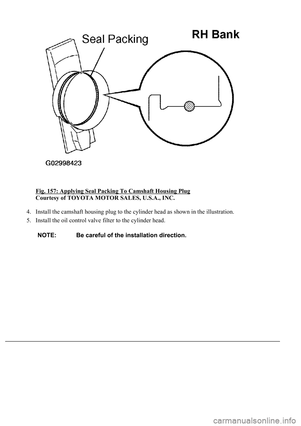
3. Apply seal packing to the camshaft housing plug.
Remove the old packing (FIPG) material.
Apply seal packing to the housing plug.
Seal packing: Part No. 08826-00080 or equivalent
Page 3438 of 4500
Fig. 157: Applying Seal Packing To Camshaft Housing Plug
Courtesy of TOYOTA MOTOR SALES, U.S.A., INC.
4. Install the camshaft housing plug to the cylinder head as shown in the illustration.
5. Install the oil control valve filter to the cylinder head.
Page 3439 of 4500
Fig. 158: Installing Camshaft Housing Plug
Courtesy of TOYOTA MOTOR SALES, U.S.A., INC.
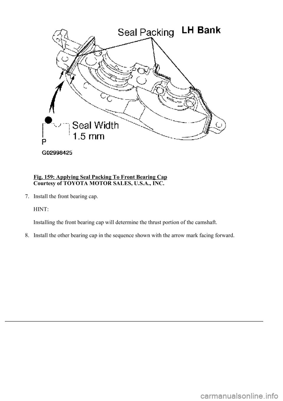
6. Apply seal packing to the front bearing cap.
Remove any old packing (FIPG) material and be care not to drop any oil on the contact
surfaces of the bearing cap and cylinder head.
Using a razor blade and gasket scraper, remove all the old packing (FIPG) material from the
gasket surfaces and groove.
Thoroughly clean all components to remove all loose material.
Using a non-residue solvent, clean both sealing surfaces.
Apply seal packing to the bearing cap as shown in the illustration.
Install a nozzle that has its opening cut to 1.5 to 2.0 mm (0.059 to 0.79 in.).
Parts must be assembled within 5 minutes of application. Otherwise the material must be
removed and reapplied.
Immediately remove the nozzle from the tube and reinstall the cap.
Seal packing: Part No. 08826-00080 or equivalent
Page 3440 of 4500
Fig. 159: Applying Seal Packing To Front Bearing Cap
Courtesy of TOYOTA MOTOR SALES, U.S.A., INC.
7. Install the front bearing cap.
HINT:
Installing the front bearing cap will determine the thrust portion of the camshaft.
8. Install the other bearin
g cap in the sequence shown with the arrow mark facing forward.
Trending: Air Conditioning Compressor, park, air condition, transmission, relay, ignition, On vehicle inspection
