LEXUS LS430 2003 Factory Repair Manual
Manufacturer: LEXUS, Model Year: 2003,
Model line: LS430,
Model: LEXUS LS430 2003
Pages: 4500, PDF Size: 87.45 MB
LEXUS LS430 2003 Factory Repair Manual
LS430 2003
LEXUS
LEXUS
https://www.carmanualsonline.info/img/36/57050/w960_57050-0.png
LEXUS LS430 2003 Factory Repair Manual
Trending: dlc3, seat memory, coolant reservoir, coolant capacity, evap, engine mechanical, belt
Page 3401 of 4500
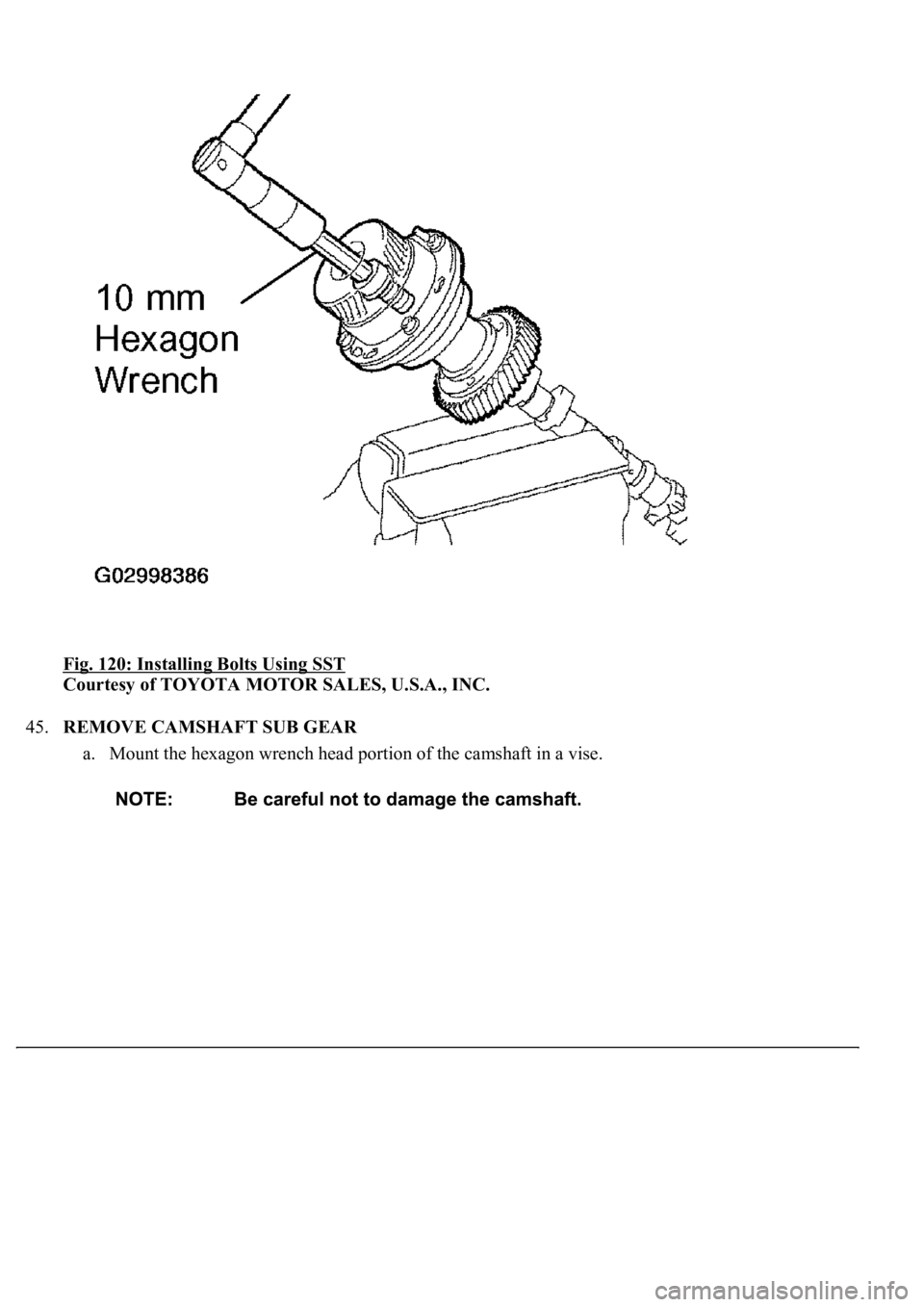
Fig. 120: Installing Bolts Using SST
Courtesy of TOYOTA MOTOR SALES, U.S.A., INC.
45.REMOVE CAMSHAFT SUB GEAR
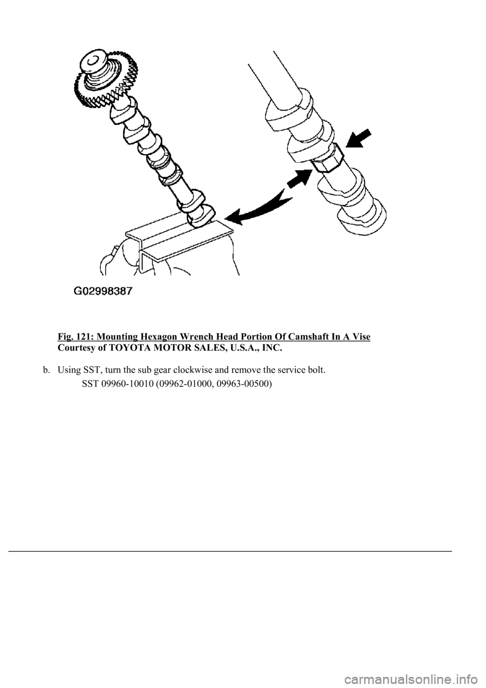
a. Mount the hexagon wrench head portion of the camshaft in a vise.
Page 3402 of 4500
Fig. 121: Mounting Hexagon Wrench Head Portion Of Camshaft In A Vise
Courtesy of TOYOTA MOTOR SALES, U.S.A., INC.
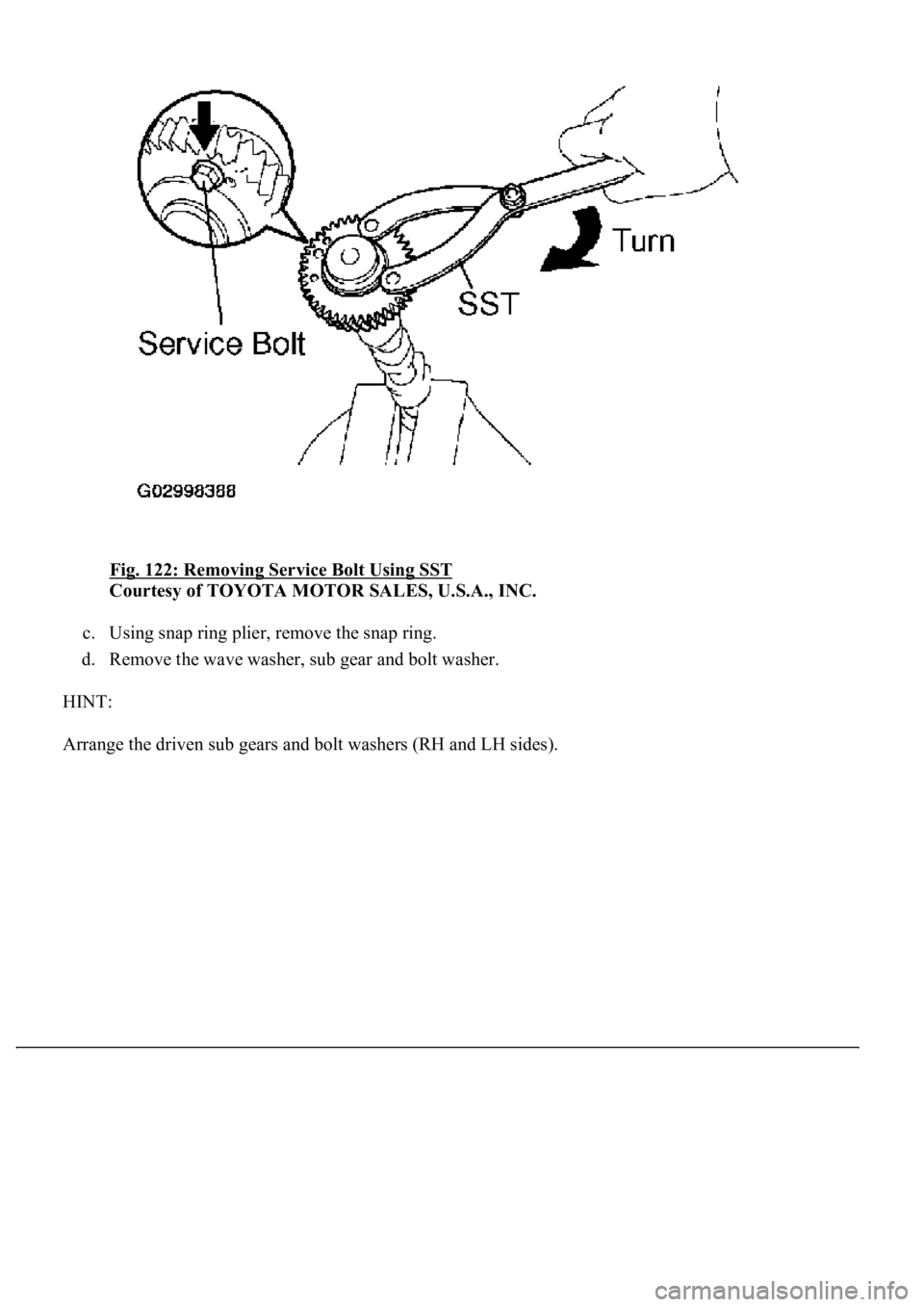
b. Using SST, turn the sub gear clockwise and remove the service bolt.
SST 09960-10010 (09962-01000, 09963-00500)
Page 3403 of 4500
Fig. 122: Removing Service Bolt Using SST
Courtesy of TOYOTA MOTOR SALES, U.S.A., INC.
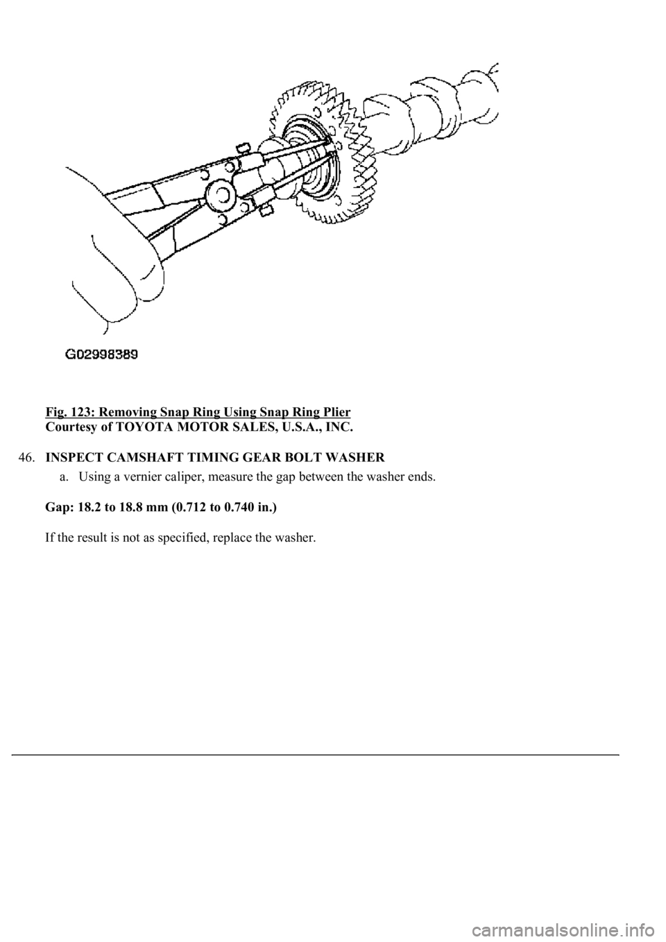
c. Using snap ring plier, remove the snap ring.
d. Remove the wave washer, sub gear and bolt washer.
HINT:
Arran
ge the driven sub gears and bolt washers (RH and LH sides).
Page 3404 of 4500
Fig. 123: Removing Snap Ring Using Snap Ring Plier
Courtesy of TOYOTA MOTOR SALES, U.S.A., INC.
46.INSPECT CAMSHAFT TIMING GEAR BOLT WASHER
a. Using a vernier caliper, measure the gap between the washer ends.
Gap: 18.2 to 18.8 mm (0.712 to 0.740 in.)
If the result is not as specified, replace the washer.
Page 3405 of 4500
Fig. 124: Measuring Gap Between Washer Ends Using Vernier Caliper
Page 3406 of 4500
Courtesy of TOYOTA MOTOR SALES, U.S.A., INC.
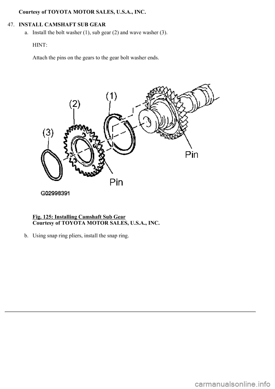
47.INSTALL CAMSHAFT SUB GEAR
a. Install the bolt washer (1), sub gear (2) and wave washer (3).
HINT:
Attach the pins on the gears to the gear bolt washer ends.
Fig. 125: Installing Camshaft Sub Gear
Courtesy of TOYOTA MOTOR SALES, U.S.A., INC.
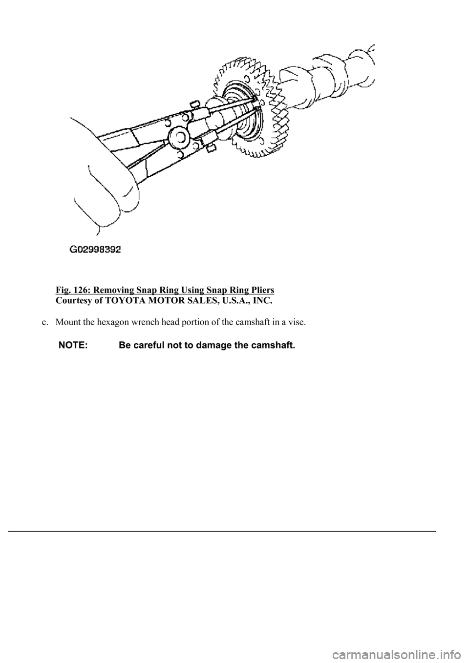
b. Using snap ring pliers, install the snap ring.
Page 3407 of 4500
Fig. 126: Removing Snap Ring Using Snap Ring Pliers
Courtesy of TOYOTA MOTOR SALES, U.S.A., INC.
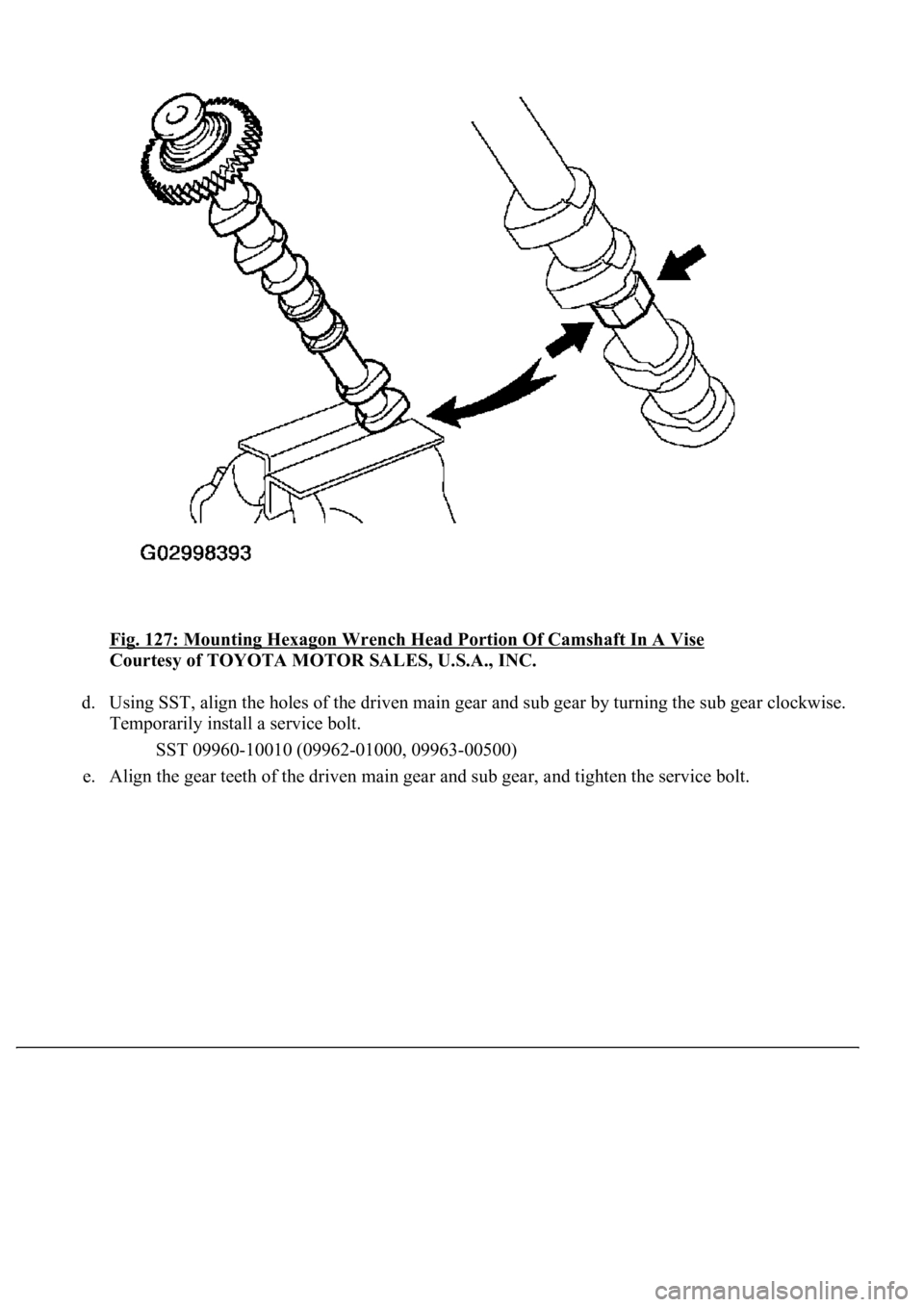
c. Mount the hexagon wrench head portion of the camshaft in a vise.
Page 3408 of 4500
Fig. 127: Mounting Hexagon Wrench Head Portion Of Camshaft In A Vise
Courtesy of TOYOTA MOTOR SALES, U.S.A., INC.
d. Using SST, align the holes of the driven main gear and sub gear by turning the sub gear clockwise.
Temporarily install a service bolt.
SST 09960-10010 (09962-01000, 09963-00500)
e. Ali
gn the gear teeth of the driven main gear and sub gear, and tighten the service bolt.
Page 3409 of 4500
Fig. 128: Aligning Holes Of Driven Main Gear And Sub Gear Using SST
Courtesy of TOYOTA MOTOR SALES, U.S.A., INC.
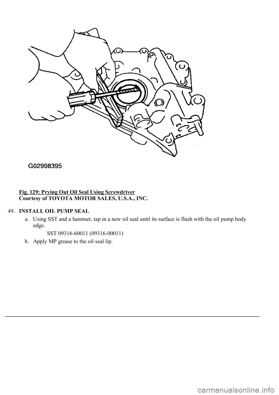
48.REMOVE OIL PUMP SEAL
a. Using a screwdriver and wooden block, pry out the oil seal.
HINT:
Tape the screwdriver tip before use.
Page 3410 of 4500
Fig. 129: Prying Out Oil Seal Using Screwdriver
Courtesy of TOYOTA MOTOR SALES, U.S.A., INC.
49.INSTALL OIL PUMP SEAL
a. Using SST and a hammer, tap in a new oil seal until its surface is flush with the oil pump body
edge.
SST 09316-60011 (09316-00011)
b. Apply MP grease to the oil seal lip.
Trending: service schedule, exhaust manifold, replacement, wheel, Spark plug firing order, On vehicle inspection, Sp1
