LEXUS LS430 2003 Factory Repair Manual
Manufacturer: LEXUS, Model Year: 2003,
Model line: LS430,
Model: LEXUS LS430 2003
Pages: 4500, PDF Size: 87.45 MB
LEXUS LS430 2003 Factory Repair Manual
LS430 2003
LEXUS
LEXUS
https://www.carmanualsonline.info/img/36/57050/w960_57050-0.png
LEXUS LS430 2003 Factory Repair Manual
Trending: climate control, bulb, window regulator, tire size, fuse box, differential, wheel bolts
Page 691 of 4500
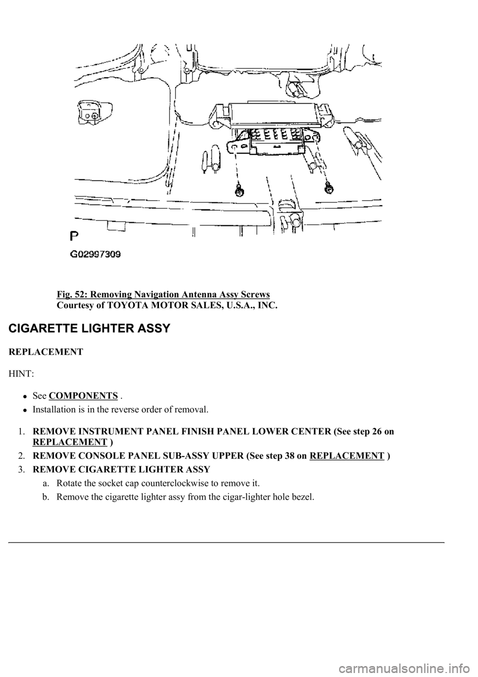
Fig. 52: Removing Navigation Antenna Assy Screws
Courtesy of TOYOTA MOTOR SALES, U.S.A., INC.
REPLACEMENT
HINT:
See COMPONENTS .
Installation is in the reverse order of removal.
1.REMOVE INSTRUMENT PANEL FINISH PANEL LOWER CENTER (See step 26 on
REPLACEMENT
)
2.REMOVE CONSOLE PANEL SUB-ASSY UPPER (See step 38 on REPLACEMENT
)
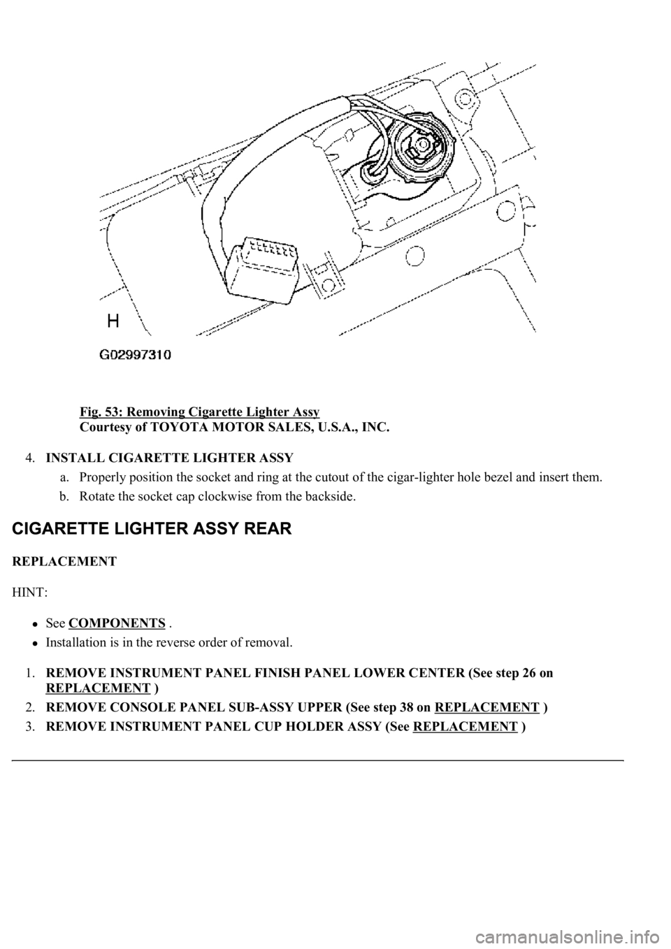
3.REMOVE CIGARETTE LIGHTER ASSY
a. Rotate the socket cap counterclockwise to remove it.
b. Remove the cigarette lighter assy from the cigar-lighter hole bezel.
Page 692 of 4500
Fig. 53: Removing Cigarette Lighter Assy
Courtesy of TOYOTA MOTOR SALES, U.S.A., INC.
4.INSTALL CIGARETTE LIGHTER ASSY
a. Properly position the socket and ring at the cutout of the cigar-lighter hole bezel and insert them.
b. Rotate the socket cap clockwise from the backside.
REPLACEMENT
HINT:
See COMPONENTS .
Installation is in the reverse order of removal.
1.REMOVE INSTRUMENT PANEL FINISH PANEL LOWER CENTER (See step 26 on
REPLACEMENT
)
2.REMOVE CONSOLE PANEL SUB-ASSY UPPER (See step 38 on REPLACEMENT
)
3.REMOVE INSTRUMENT PANEL CUP HOLDER ASSY (See REPLACEMENT
)
Page 693 of 4500
4.REMOVE CONSOLE UPPER REAR PANEL SUB-ASSY (See step 39 on REPLACEMENT )
5.REMOVE CONSOLE BOX CARPET (See step 40 on REPLACEMENT
)
6.REMOVE REAR CONSOLE ARMREST ASSY (See step 41 on REPLACEMENT
)
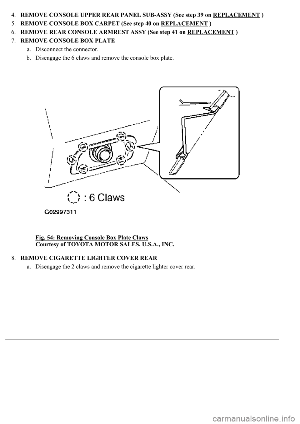
7.REMOVE CONSOLE BOX PLATE
a. Disconnect the connector.
b. Disengage the 6 claws and remove the console box plate.
Fig. 54: Removing Console Box Plate Claws
Courtesy of TOYOTA MOTOR SALES, U.S.A., INC.
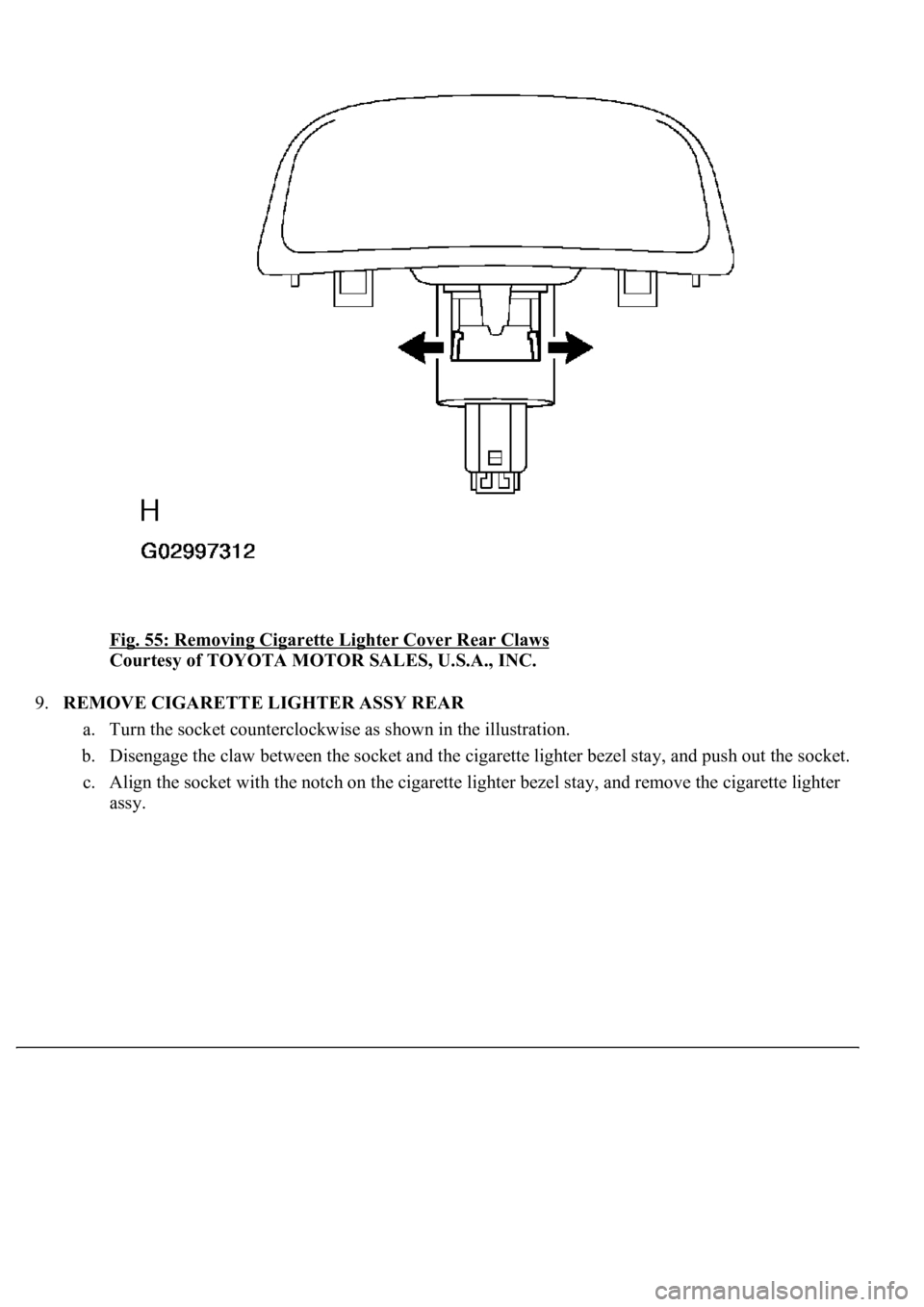
8.REMOVE CIGARETTE LIGHTER COVER REAR
a. Disengage the 2 claws and remove the cigarette lighter cover rear.
Page 694 of 4500
Fig. 55: Removing Cigarette Lighter Cover Rear Claws
Courtesy of TOYOTA MOTOR SALES, U.S.A., INC.
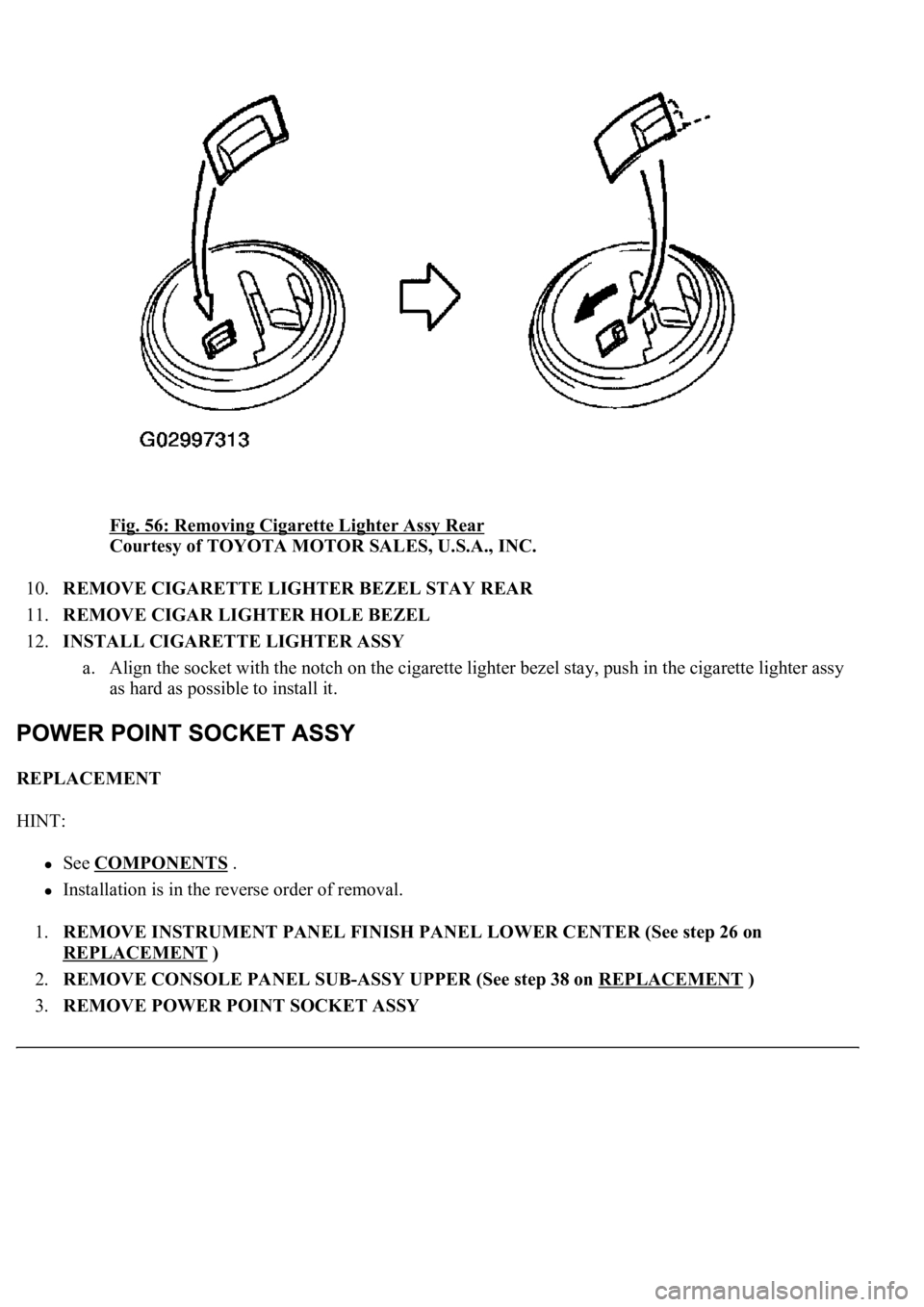
9.REMOVE CIGARETTE LIGHTER ASSY REAR
a. Turn the socket counterclockwise as shown in the illustration.
b. Disengage the claw between the socket and the cigarette lighter bezel stay, and push out the socket.
c. Align the socket with the notch on the cigarette lighter bezel stay, and remove the cigarette lighter
ass
y.
Page 695 of 4500
Fig. 56: Removing Cigarette Lighter Assy Rear
Courtesy of TOYOTA MOTOR SALES, U.S.A., INC.
10.REMOVE CIGARETTE LIGHTER BEZEL STAY REAR
11.REMOVE CIGAR LIGHTER HOLE BEZEL
12.INSTALL CIGARETTE LIGHTER ASSY
a. Align the socket with the notch on the cigarette lighter bezel stay, push in the cigarette lighter assy
as hard as possible to install it.
REPLACEMENT
HINT:
See COMPONENTS .
Installation is in the reverse order of removal.
1.REMOVE INSTRUMENT PANEL FINISH PANEL LOWER CENTER (See step 26 on
REPLACEMENT
)
2.REMOVE CONSOLE PANEL SUB-ASSY UPPER (See step 38 on REPLACEMENT
)
3.REMOVE POWER POINT SOCKET ASSY
Page 696 of 4500
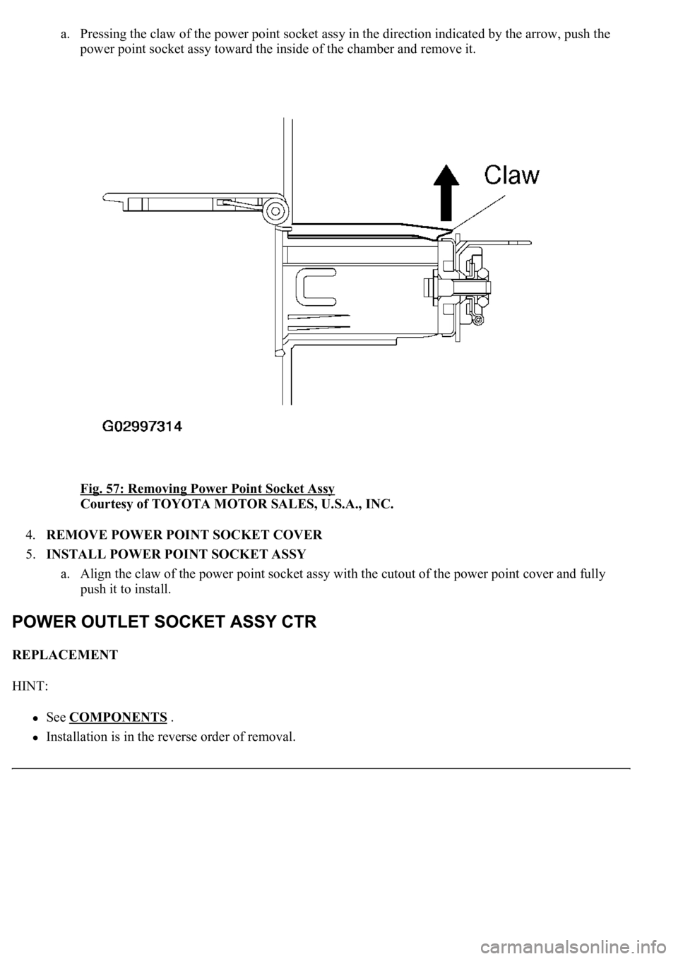
a. Pressing the claw of the power point socket assy in the direction indicated by the arrow, push the
power point socket assy toward the inside of the chamber and remove it.
Fig. 57: Removing Power Point Socket Assy
Courtesy of TOYOTA MOTOR SALES, U.S.A., INC.
4.REMOVE POWER POINT SOCKET COVER
5.INSTALL POWER POINT SOCKET ASSY
a. Align the claw of the power point socket assy with the cutout of the power point cover and fully
push it to install.
REPLACEMENT
HINT:
See COMPONENTS .
Installation is in the reverse order of removal.
Page 697 of 4500
1.REMOVE INSTRUMENT CLUSTER FINISH PANEL SUB-ASSY CENTER (See step 31 on
REPLACEMENT
)
2.REMOVE INSTRUMENT PANEL CUP HOLDER ASSY (See REPLACEMENT
)
3.REMOVE CONSOLE UPPER REAR PANEL SUB-ASSY (See step 39 on REPLACEMENT
)
4.REMOVE CONSOLE BOX CARPET (See step 40 on REPLACEMENT
)
5.REMOVE REAR CONSOLE ARMREST ASSY (See step 41 on REPLACEMENT
)
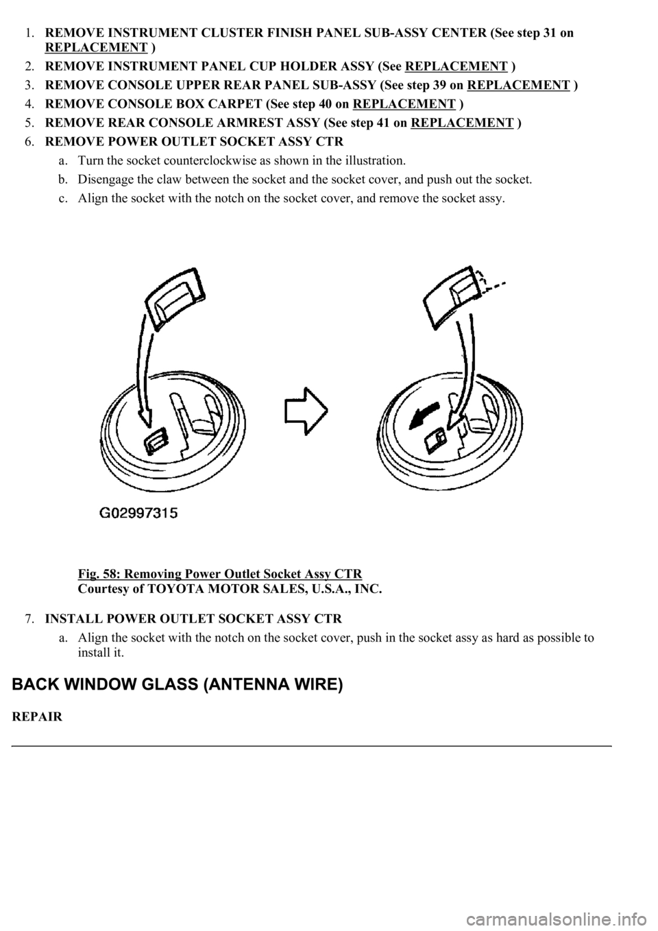
6.REMOVE POWER OUTLET SOCKET ASSY CTR
a. Turn the socket counterclockwise as shown in the illustration.
b. Disengage the claw between the socket and the socket cover, and push out the socket.
c. Align the socket with the notch on the socket cover, and remove the socket assy.
Fig. 58: Removing Power Outlet Socket Assy CTR
Courtesy of TOYOTA MOTOR SALES, U.S.A., INC.
7.INSTALL POWER OUTLET SOCKET ASSY CTR
a. Align the socket with the notch on the socket cover, push in the socket assy as hard as possible to
install it.
REPAIR
Page 698 of 4500
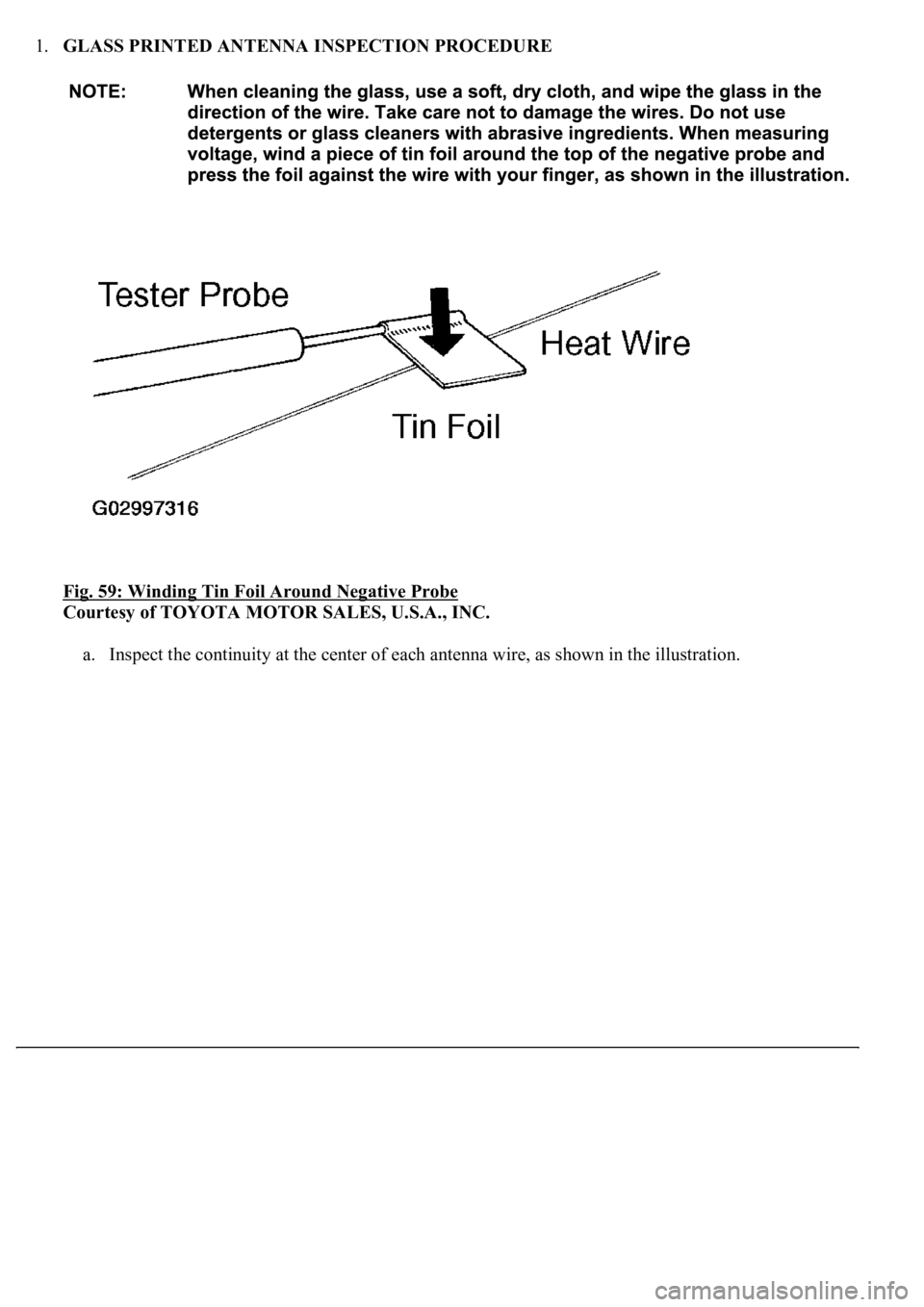
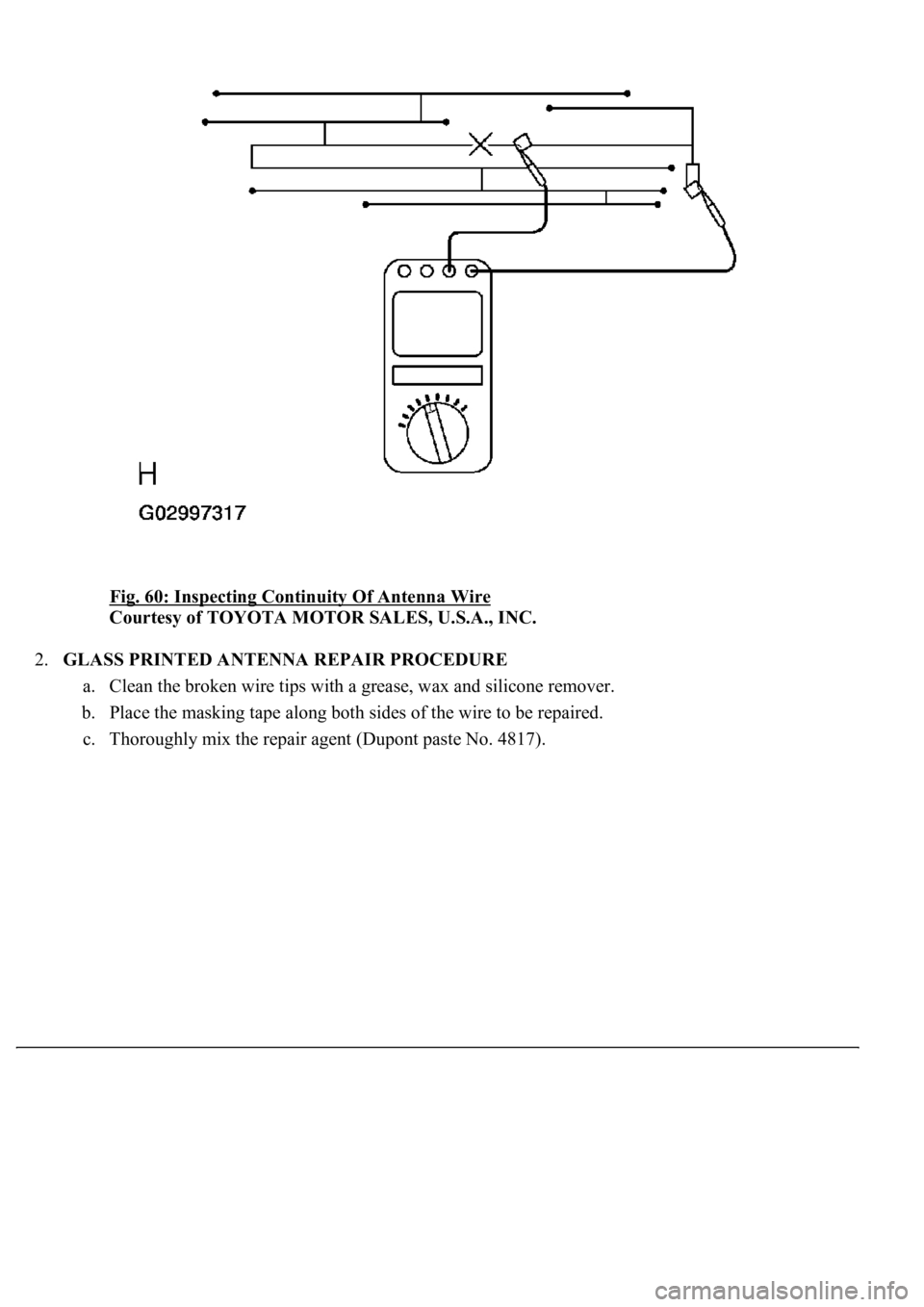
1.GLASS PRINTED ANTENNA INSPECTION PROCEDURE
Fig. 59: Winding Tin Foil Around Negative Probe
Courtesy of TOYOTA MOTOR SALES, U.S.A., INC.
a. Inspect the continuity at the center of each antenna wire, as shown in the illustration.
Page 699 of 4500
Fig. 60: Inspecting Continuity Of Antenna Wire
Courtesy of TOYOTA MOTOR SALES, U.S.A., INC.
2.GLASS PRINTED ANTENNA REPAIR PROCEDURE
a. Clean the broken wire tips with a grease, wax and silicone remover.
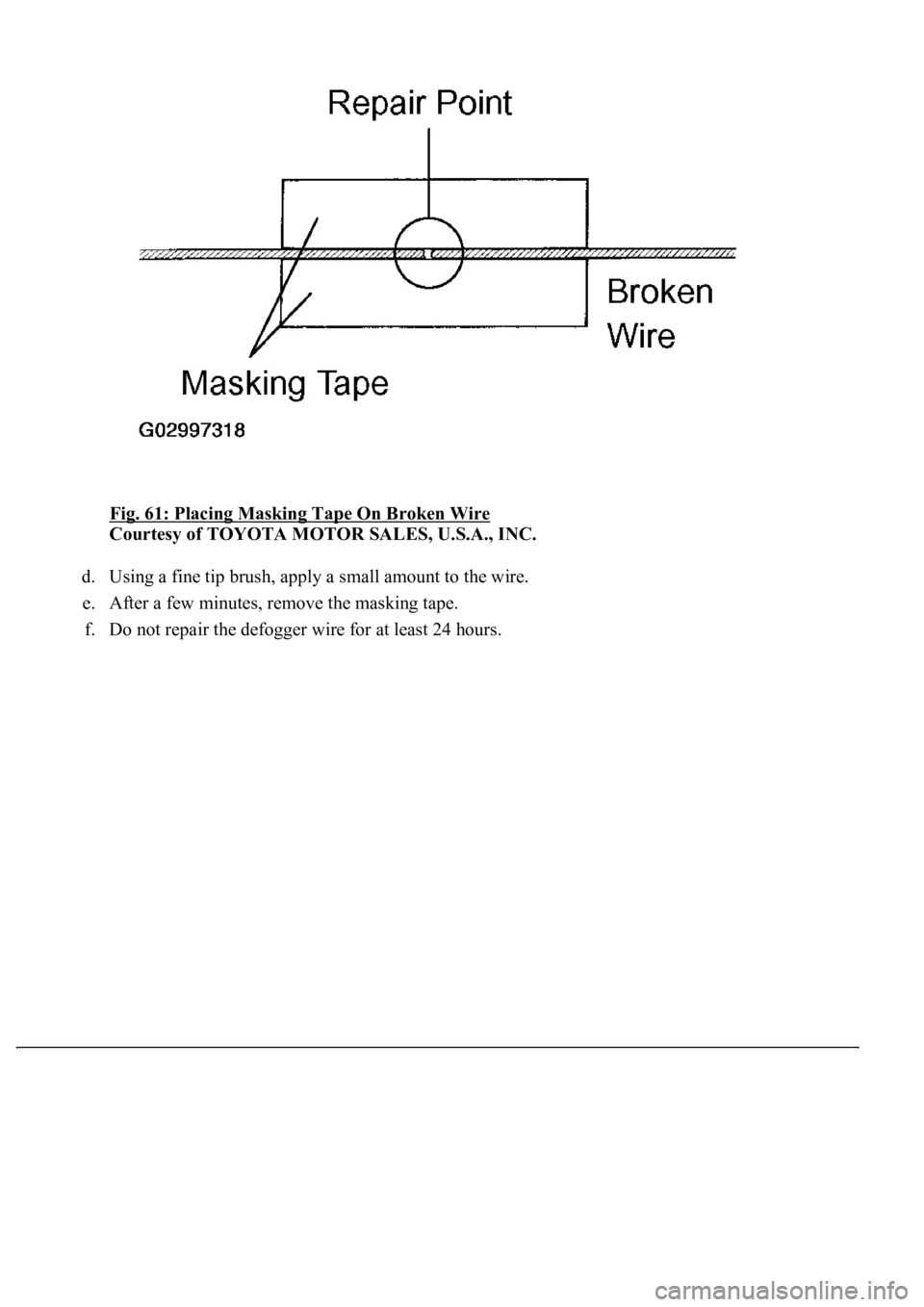
b. Place the masking tape along both sides of the wire to be repaired.
c. Thorou
ghly mix the repair agent (Dupont paste No. 4817).
Page 700 of 4500
Fig. 61: Placing Masking Tape On Broken Wire
Courtesy of TOYOTA MOTOR SALES, U.S.A., INC.
d. Using a fine tip brush, apply a small amount to the wire.
e. After a few minutes, remove the masking tape.
f. Do not repair the defo
gger wire for at least 24 hours.
Trending: seat adjustment, tire pressure, check transmission fluid, instrument cluster, change time, Spd, replacement
