MAZDA 6 2002 Workshop Manual Suplement
Manufacturer: MAZDA, Model Year: 2002, Model line: 6, Model: MAZDA 6 2002Pages: 909, PDF Size: 17.16 MB
Page 381 of 909

TROUBLESHOOTING
F2–229
F2
ENGINE CONTROL SYSTEM OPERATION INSPECTIONA6E408018881230Intake Shutter Valve Operation Inspection
1. Start the engine and warm up completely.
2. Turn off the A/C switch.
3. Connect the WDS or equivalent to the DLC-2.
4. Monitor the following PIDs using the WDS or equivalent.
—If not as specified, inspect each sensor and related harness.
ECT PID
Above 60 °C {140 °F}
MAF PID
1.7—1.9 V
RPM PID
725—825 rpm
Note
•The position of the shutter valve, VSC shutter valve and EGR valve may not be as specified when idle
speed is maintained for several minutes. If this occurs, briefly increase engine speed to 1,500 rpm and
then re-check the position at idle speed.
5. Increase the engine speed and inspect that the intake shutter valve position changes as specified.
•If not as specified, inspect the following.
—Vacuum hose
—Intake shutter solenoid valve actuator
—Intake shutter solenoid valve and related harness.
Specification
Guide Blade Actuator Operation Inspection
1. Start the engine and warm up completely.
2. Verify that the A/C switch is off.
3. Connect the WDS or equivalent to the DLC-2.
4. Monitor the following PIDs using the WDS or equivalent.
—If not as specified, inspect each sensor and related harness.
ECT PID
Above 60 °C {140 °F}
MAF PID
1.7—1.9 V
RPM PID
725—825 rpm
ACSW PID
OFF
5. Inspect that the guide blade actuator position changes as specified.
•If not as specified, inspect the following.
—Vacuum hose
—Guide blade actuator
—VBC solenoid valve and related harness.
Specification
*1 : Just after turning engine switch off
*2 : 0 to 5 seconds after turning engine switch to OFF
*3 : Guide blade actuator begins to pull back
Engine speed (rpm) Intake shutter valve position
775 Halfway open
1,800 Fully open
2,500 Fully open
Above 3,400 Fully open
Engine switch
positionEngine speed
(rpm)Guide blade
actuator position
ON 775 Closed
OFF
*10*3Closed
OFF
*20 Open
Page 382 of 909

F2–230
TROUBLESHOOTING
Cooling Fan No.1/Cooling Fan No.2 Control System Inspection
Cooling fan No.1/cooling fan No.2 system operation
Cooling fan relay No.2
1. Connect the WDS or equivalent to DLC-2.
2. Verify that ECT PID is below main fan operating temperature.
3. Verify that A/C switch and fan switch are off.
4. Turn the engine switch to ON.
5. Verify that the cooling fan No.2 is not operating.
•If the cooling fan No.2 is operating:
(1) Select FAN PID.
(2) Send OFF and verify the cooling fan No.2 is off.
•If the cooling fan No.2 is on, inspect the following.
—Cooling fan relay No.2 stuck in closed position
—Short to GND circuit between cooling fan relay No.2 and PCM terminal 76
—Short to power in circuit at cooling fan relay No.2
—DTC for ECT sensor (P0117, P0118)
•If the cooling fan relay No.2 is off, inspect the following.
—Short to GND circuit between refrigerant pressure switch and PCM terminal 84
—DTC for ECT sensor (P0117, P0118)
6. Start the engine.
7. Verify that the cooling fan No.2 is operating when engine is hot.
•If the cooling fan No.2 does not operate, perform the following.
1. Connect WDS or equivalent to the DLC-2.
2. Select FAN PID.
3. Operate cooling fan No.2 by sending ON command.
4. Inspect if the operation sound is heard from the cooling fan relay No.2.
•If the operation sound is heard, inspect the wiring harness, connectors and cooling fan motor No.2.
•If the operation sound is not heard, inspect cooling fan relay No.2 and open circuit wiring harness
and connectors.
8. Turn the A/C switch and fan switch on.
9. Verify that cooling fan No.2 is operating.
•If fan does not operate, inspect A/C system.
Cooling fan relay No.1
1. Verify that A/C switch and fan switch are off.
2. Start the engine and let it idle.
3. Verify that the cooling fan No.1 is not operating.
•If cooling fan No.1 is operating, inspect for the following.
—Cooling fan relay No.1 is stuck in closed position.
—Short to power in circuit between cooling fan relay No.1 and cooling fan No.1
—Short to GND in circuit between refrigerant pressure switch and PCM terminal 84
—Short to GND circuit between cooling fan relay No.1 and PCM terminal 102
4. Turn the A/C switch and fan switch on.
5. Verify that the cooling fan No.1 is operating and operation sound of A/C compressor magnetic clutch is heard.
Engine conditionCooling fan
relay No.2Cooling fan
relay No.1
ECT below 100°C
{212°F}OFF OFF
ECT above 100°C
{212°F} (until below
97°C {207°F})ON OFF
ECT above 108°C
{228°F} (until below
105°C {230°F})ON ON
A/C and fan switches
are on.ON ON
ECT sensor
malfunctionON ON
Page 383 of 909

TROUBLESHOOTING
F2–231
F2
6. Turn the A/C switch and fan switch off.
•If the cooling fan No.1 does not operate but operation sound of A/C compressor magnetic clutch is heard,
inspect for the following.
—Open circuit between ignition switch and cooling fan relay No.1
—Open circuit between battery and cooling fan relay No.1
—Open circuit between cooling fan relay No.1 and PCM terminal 102
—Open circuit between cooling fan relay No.1 and cooling fan motor No.1 or fan motor GND
—Cooling fan relay No.1 is stuck open.
—Cooling fan motor No.1
•If both additional fan and A/C compressor do not operate, inspect the following.
—A/C system
End Of Sie
Page 384 of 909

G–1
G
GENGINE ELECTRICAL SYSTEM
OUTLINE............................................................... G-2
OUTLINE OF CONSTRUCTION......................... G-2
SPECIFICATIONS .............................................. G-2
STRUCTURAl VIEW ........................................... G-3
OUTLINE............................................................... G-4
SUPPLEMENTAL SERVICE INFORMATION .... G-4
LOCATION INDEX .............................................. G-4
CHARGING SYSTEM............................................ G-5
BATTERY REMOVAL/INSTALLATION .............. G-5
BATTERY INSPECTION..................................... G-6
BATTERY RECHARGING .................................. G-6
GENERATOR REMOVAL/INSTALLATION ........ G-7
GENERATOR INSPECTION .............................. G-7
STARTING SYSTEM............................................. G-9
STARTER REMOVAL/INSTALLATION .............. G-9
STARTER INSPECTION .................................. G-11 FEATURES
SERVICE
Page 385 of 909

G–2
OUTLINE
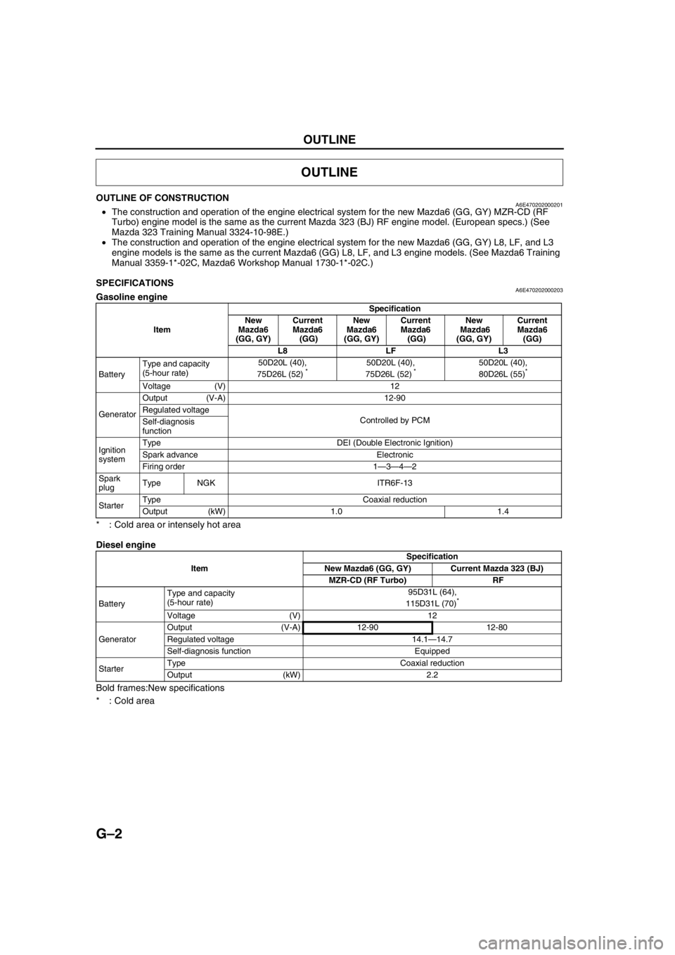
OUTLINE OF CONSTRUCTIONA6E470202000201•The construction and operation of the engine electrical system for the new Mazda6 (GG, GY) MZR-CD (RF
Turbo) engine model is the same as the current Mazda 323 (BJ) RF engine model. (European specs.) (See
Mazda 323 Training Manual 3324-10-98E.)
•The construction and operation of the engine electrical system for the new Mazda6 (GG, GY) L8, LF, and L3
engine models is the same as the current Mazda6 (GG) L8, LF, and L3 engine models. (See Mazda6 Training
Manual 3359-1*-02C, Mazda6 Workshop Manual 1730-1*-02C.)
End Of Sie
SPECIFICATIONSA6E470202000203Gasoline engine
* : Cold area or intensely hot area
Diesel engine
Bold frames:New specifications
* : Cold area
End Of Sie
OUTLINE
ItemSpecification
New
Mazda6
(GG, GY)Current
Mazda6
(GG)New
Mazda6
(GG, GY)Current
Mazda6
(GG)New
Mazda6
(GG, GY)Current
Mazda6
(GG)
L8 LF L3
BatteryType and capacity
(5-hour rate)50D20L (40),
75D26L (52)
*50D20L (40),
75D26L (52) *50D20L (40),
80D26L (55)*
Voltage (V) 12
GeneratorOutput (V-A) 12-90
Regulated voltage
Controlled by PCM
Self-diagnosis
function
Ignition
systemType DEI (Double Electronic Ignition)
Spark advance Electronic
Firing order 1—3—4—2
Spark
plugType NGK ITR6F-13
StarterType Coaxial reduction
Output (kW) 1.0 1.4
ItemSpecification
New Mazda6 (GG, GY) Current Mazda 323 (BJ)
MZR-CD (RF Turbo) RF
BatteryType and capacity
(5-hour rate)95D31L (64),
115D31L (70)
*
Voltage (V) 12
GeneratorOutput (V-A) 12-90 12-80
Regulated voltage 14.1—14.7
Self-diagnosis function Equipped
StarterType Coaxial reduction
Output (kW) 2.2
Page 386 of 909

OUTLINE
G–3
G
STRUCTURAL VIEWA6E470202000205MZR-CD (RF Turbo)
.
End Of Sie
3
1
2
A6E4702W100
1Battery
2 Generator 3Starter
Page 387 of 909

G–4
OUTLINE
SUPPLEMENTAL SERVICE INFORMATIONA6E470202000204•The following changes and/or additions have been made since publication of the Mazda6 Workshop Manual
(1730-1*-02C).
Battery
•Removal/Installation procedure has been added. (MZR-CD (RF Turbo) engine model)
•Inspection procedure has been added. (MZR-CD (RF Turbo) engine model)
•Recharging procedure has been added. (MZR-CD (RF Turbo) engine model)
Generator
•Removal/Installation procedure has been added. (MZR-CD (RF Turbo) engine model)
•Inspection procedure has been added. (MZR-CD (RF Turbo) engine model)
Starter
•Removal/Installation procedure has been added.
•Inspection procedure has been added. (MZR-CD (RF Turbo) engine model)
End Of Sie
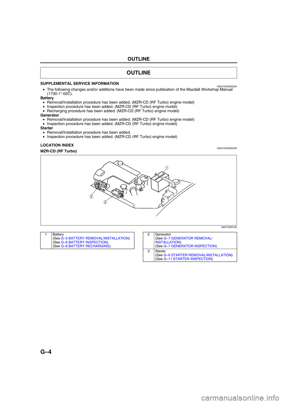
LOCATION INDEXA6E470202000206MZR-CD (RF Turbo)
.
End Of Sie
OUTLINE
3
1
2
A6E4702W100
1 Battery
(See G–5 BATTERY REMOVAL/INSTALLATION)
(See G–6 BATTERY INSPECTION)
(See G–6 BATTERY RECHARGING)2 Generator
(See G–7 GENERATOR REMOVAL/
INSTALLATION)
(See G–7 GENERATOR INSPECTION)
3Starter
(See G–9 STARTER REMOVAL/INSTALLATION)
(See G–11 STARTER INSPECTION)
Page 388 of 909

CHARGING SYSTEM
G–5
G
BATTERY REMOVAL/INSTALLATIONA6E471018520201MZR-CD (RF Turbo)
1. Remove in the order indicated in the table.
2. Install in the reverse order of removal.
End Of Sie
CHARGING SYSTEM
4.0—6.8 N·m
{40.8—69.3 kgf·cm, 35.5—60.1 in·lbf}
7.9—11.7 N·m
{80.6—119.3 kgf·cm, 70.0—103.5 in·lbf}
5
4
3
1
2
A6E4710W103
1 Negative battery cable
2 Positive battery cable
3 Battery clamp4 Battery
5 Battery tray
Page 389 of 909

G–6
CHARGING SYSTEM
BATTERY INSPECTIONA6E471018520202MZR-CD (RF Turbo)
Battery
1. Inspect the battery with the following procedure.
Load test chart
Battery positive voltage with load
Back-up Current
1. Verify that the engine switch is off and that the engine key has been removed.
2. Disconnect the negative battery cable.
Caution
•Operating electrical loads while measuring the back-up current can damage the circuit tester.
3. Measure the back-up current between the negative battery terminal and the negative battery cable.
(1) If the current exceeds the maximum, remove the fuses in the main fuse block and the fuse block one by
one while measuring the back-up current.
(2) Inspect and repair harnesses and connectors on the fuse where the current has been reduced.
Back-up current
20 mA max.
End Of Sie
BATTERY RECHARGINGA6E471018520203MZR-CD (RF Turbo)
Caution
•To avoid damage to the battery, do not quick charge for over 30 min.
•When disconnecting the battery, remove the negative cable first and install it last to prevent
damage to electrical components or the battery.
•To avoid deformation or damage to the battery, remove the battery plugs while charging the
battery.
Step Inspection Result Action
1Measure open circuit
voltage of battery.Above
12.4 VGo to Step
3.
Below
12.4 VGo to next
step.
2Quick-charge for 30 min.
and recheck voltage.Above
12.4 VGo to next
step.
Below
12.4 VReplace
battery.
3Apply load test (see load
test chart) to battery using a
battery load tester and
record battery voltage after
15 s. Is voltage more than
specification?YesBattery
okay.
NoReplace
battery.
Battery Load (A)
95D31L (64) 250
115D31L (70) 320
Approximate battery temp. Minimum voltage (V)
21°C {70°F} 9.6
15°C {60°F} 9.5
10°C {50°F} 9.4
4°C {40°F} 9.3
–1°C {30°F} 9.1
–7°C {20°F} 8.9
–12°C {10°F} 8.7
–18°C {0°F} 8.5
Page 390 of 909

CHARGING SYSTEM
G–7
G
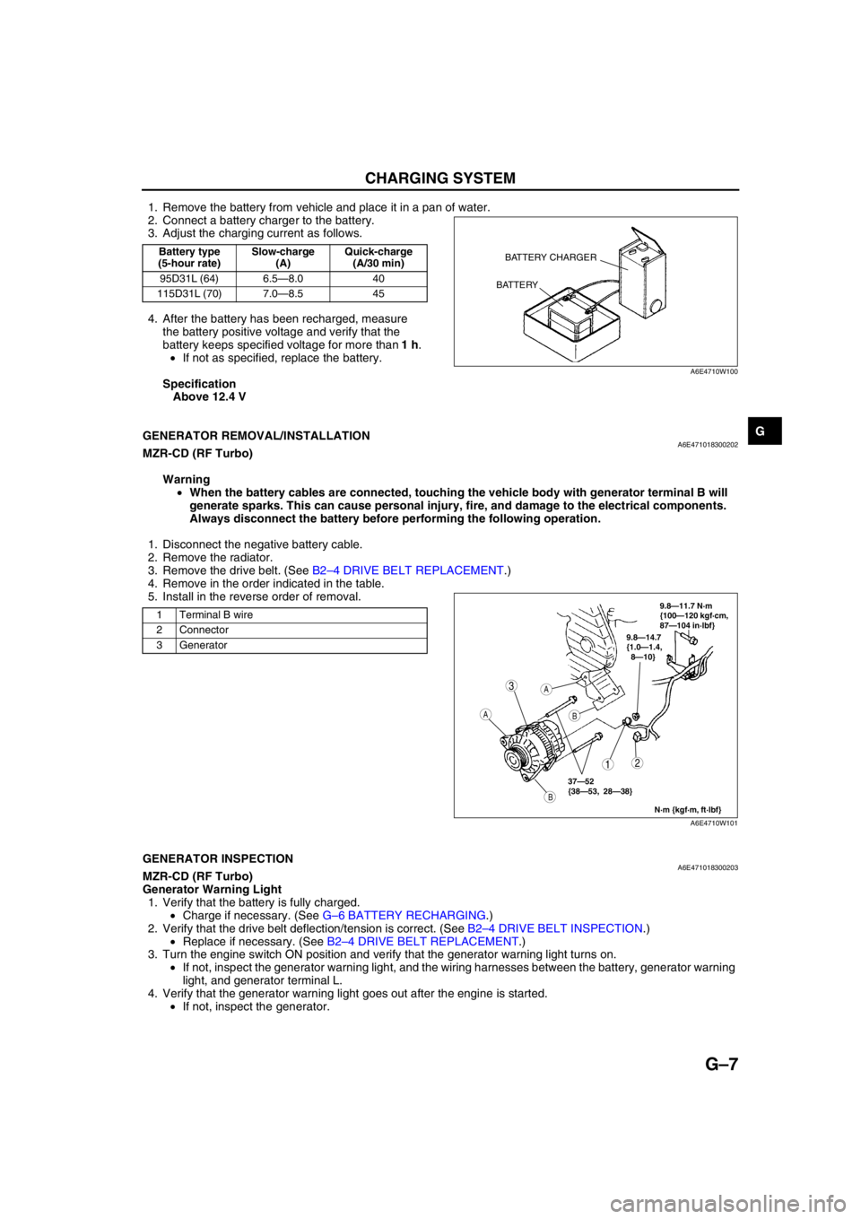
1. Remove the battery from vehicle and place it in a pan of water.
2. Connect a battery charger to the battery.
3. Adjust the charging current as follows.
4. After the battery has been recharged, measure
the battery positive voltage and verify that the
battery keeps specified voltage for more than 1 h.
•If not as specified, replace the battery.
Specification
Above 12.4 V
End Of Sie
GENERATOR REMOVAL/INSTALLATIONA6E471018300202MZR-CD (RF Turbo)
Warning
•When the battery cables are connected, touching the vehicle body with generator terminal B will
generate sparks. This can cause personal injury, fire, and damage to the electrical components.
Always disconnect the battery before performing the following operation.
1. Disconnect the negative battery cable.
2. Remove the radiator.
3. Remove the drive belt. (See B2–4 DRIVE BELT REPLACEMENT.)
4. Remove in the order indicated in the table.
5. Install in the reverse order of removal.
End Of SieGENERATOR INSPECTIONA6E471018300203MZR-CD (RF Turbo)
Generator Warning Light
1. Verify that the battery is fully charged.
•Charge if necessary. (See G–6 BATTERY RECHARGING.)
2. Verify that the drive belt deflection/tension is correct. (See B2–4 DRIVE BELT INSPECTION.)
•Replace if necessary. (See B2–4 DRIVE BELT REPLACEMENT.)
3. Turn the engine switch ON position and verify that the generator warning light turns on.
•If not, inspect the generator warning light, and the wiring harnesses between the battery, generator warning
light, and generator terminal L.
4. Verify that the generator warning light goes out after the engine is started.
•If not, inspect the generator.
Battery type
(5-hour rate)Slow-charge
(A)Quick-charge
(A/30 min)
95D31L (64) 6.5—8.0 40
115D31L (70) 7.0—8.5 45BATTERY CHARGER
BATTERY
A6E4710W100
1 Terminal B wire
2 Connector
3 Generator
3
12
A
B
A
B
9.8—14.7
{1.0—1.4,
8—10}
N·m {kgf·m, ft·lbf}
37—52
{38—53, 28—38}
9.8—11.7 N·m
{100—120 kgf·cm,
87—104 in·lbf}
A6E4710W101