MAZDA 6 2002 Workshop Manual Suplement
Manufacturer: MAZDA, Model Year: 2002, Model line: 6, Model: MAZDA 6 2002Pages: 909, PDF Size: 17.16 MB
Page 411 of 909

MANUAL TRANSAXLE
J2–9
J2
No.1 Engine Mount Bracket Removal Note
1. Separate the fuel pipe nearby engine hanger.
2. Support the engine using the SST before
removing the No.1 engine mount.
3. Remove the No.1 engine mount.
Manual Transaxle Removal Note
1. Remove the stud of the No.4 engine mount.
2. Loosen the SST (49 E017 5A0)and lean the
engine toward the transaxle.
3. Support the transaxle on a jack.
4. Remove the transaxle mounting bolts.
5. Remove the transaxle.
9 Lower arm (front, rear) ball joint
(See Section R)
10 Damper fork
11 Tie-rod end ball joint
(See N–8 STEERING GEAR AND LINKAGE
(MZR-CD (RF Turbo)) REMOVAL/INSTALLATION)
12 Stabilizer control link
13 Drive shaft (left side)
(SeeSection M)
14 Drive shaft (right side)
(SeeSection M)
15 Joint shaft
(SeeSection M)
16 Flexible pipe
(See F2–57 EXHAUST SYSTEM REMOVAL/
INSTALLATION)17 No.1 engine mount
(See J2–9 No.1 Engine Mount Bracket Removal
Note)
(See J2–11 No.1 Engine Mount Installation Note)
18 Crossmember bracket
19 Crossmember, steering pipe
(See Section R)
20 No.4 engine mount bracket
(See J2–10 No.4 Engine Mount Installation Note)
21 No.4 engine mount rubber
(See J2–10 No.4 Engine Mount Installation Note)
22 Transaxle mounting bolt (lower side)
23 Manual transaxle
(See J2–9 Manual Transaxle Removal Note)
(See J2–10 Manual Transaxle Installation Note)
49 E017 5A0
A6E5212W019
STUD
A6E5212W020
A6E5212W021
Page 412 of 909

J2–10
MANUAL TRANSAXLE
Manual Transaxle Installation Note
1. Set the transaxle on a jack and lift into place.
2. Install the transaxle mounting bolts.
3. Install the stud of the No.4 engine mount.
Tightening torque
27.4—40.2 N·m
{2.80—4.09 kgf·m, 20.2—29.6 ft·lbf}
4. Tighten the SST (49 E017 5A0)so that the engine
is located at the specified position.
No.4 Engine Mount Installation Note
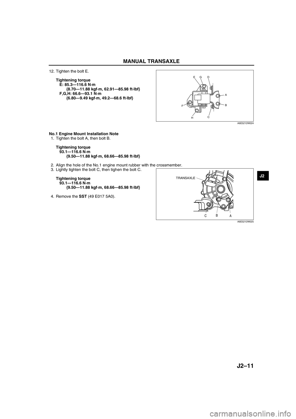
1. Verify that the No.4 engine mount rubber is installed as shown.
2. Lightly tighten the bolt A and B.
3. Align the contacted area to front frame of the bolt C to the front frame.
4. Tighten the bolt A, then bolt B.
5. Tighten the bolt C, then bolt D.
Tightening torque
A,B,C,D: 58.8—80.4 N·m
{6.00—8.19 kgf·m, 43.4—59.2 ft·lbf}
6. Verify that the No.4 engine mount bracket is
installed as shown.
7. Lightly tighten the bolt E.
8. Set the transaxle on a garage jack and lift it.
9. Align the hole of the No.4 engine mount bracket
with the stud bolts of transaxle.
10. Lightly tighten the nut F, G and bolt H.
11. Tighten the nut F, G in order of F→G, then bolt H.
A6E5212W022
STUD
A6E5212W020
D
H
C
FB
A
GE
A6E5212W024
TRANSAXLE
GARAGE JACK
A6E5212W023
Page 413 of 909

MANUAL TRANSAXLE
J2–11
J2
12. Tighten the bolt E.
Tightening torque
E: 85.3—116.6 N·m
{8.70—11.88 kgf·m, 62.91—85.98 ft·lbf}
F,G,H: 66.6—93.1 N·m
{6.80—9.49 kgf·m, 49.2—68.6 ft·lbf}
No.1 Engine Mount Installation Note
1. Tighten the bolt A, then bolt B.
Tightening torque
93.1—116.6 N·m
{9.50—11.88 kgf·m, 68.66—85.98 ft·lbf}
2. Align the hole of the No.1 engine mount rubber with the crossmember.
3. Lightly tighten the bolt C, then tighen the bolt C.
Tightening torque
93.1—116.6 N·m
{9.50—11.88 kgf·m, 68.66—85.98 ft·lbf}
4. Remove the SST (49 E017 5A0).
End Of Sie
D
H
C
FB
A
GE
A6E5212W024
TRANSAXLE
CB
A
A6E5212W025
Page 414 of 909

J2–12
SHIFT MECHANISM
SHIFT MECHANISM REMOVAL/INSTALLATIONA6E5214460102011. Remove the battery and battery tray.
2. Remove the air cleaner component. (See F2–36 INTAKE-AIR SYSTEM REMOVAL/INSTALLATION.)
3. Remove the dashboard compleat. (See Section S.)
4. Remove the SAS control module. (See Section T.)
5. Remove the climate control unit. (See Section U.)
6. Remove the rear heat duct. (See Section U.)
7. Remove in the order indicated in the table.
8. Install in the reverse order of removal.
9. After installation, verify that the shift lever can be shifted smoothly into each position.
.
SHIFT MECHANISM
7
5
A
A
4
3
3
6
6.86—9.8
{70—99 kgf·cm, 61—85 in·lbf}
15.68—22.54
{1.599—2.298,
11.57—16.62} 7.8—10.8
{80—110 kgf·cm,
69.5—95.4 in·lbf}
1
2
N·m {kgf·m, ft·lbf}
15.68—22.54
{1.599—2.298,
11.57—16.62}
A6E5214W001
1 Shift lever knob
2 Boot panel
3 Clip
4 Seal plate5 Select cable
(See J2–13 Select Cable Installation Note)
6 Shift cable
7 Sift lever component
Page 415 of 909

SHIFT MECHANISM
J2–13
J2
Select Cable Installation Note
1. Remove the center console.
2. Make sure that the shift lever (transaxle side) is in neutral.
3. Unlock the lock pice of the select cable (shift lever
side) in the order shown in the figure.
4. Shift the sift lever to neutral.
5. Lock the lock pice of the selector cable (shift
cable side) in the order shown in the figure.
6. Install the center console.
7. Shift the shift lever from neutral to other position,
and make sure that there are no other
components in that area to interfere with the
lever.
End Of Sie
LOCK PIECE SAFETY
LOCK
1
2
A6E5214W002
LOCK PIECE SAFETY
LOCK
2
1
A6E5214W003
Page 416 of 909
![MAZDA 6 2002 Workshop Manual Suplement K2–1
K2
K2AUTOMATIC TRANSAXLE [JA5AX-EL]
OUTLINE.............................................................. K2-3
FEATURES ........................................................ K2-3
SPECIFICATI MAZDA 6 2002 Workshop Manual Suplement K2–1
K2
K2AUTOMATIC TRANSAXLE [JA5AX-EL]
OUTLINE.............................................................. K2-3
FEATURES ........................................................ K2-3
SPECIFICATI](/img/28/57057/w960_57057-415.png)
K2–1
K2
K2AUTOMATIC TRANSAXLE [JA5AX-EL]
OUTLINE.............................................................. K2-3
FEATURES ........................................................ K2-3
SPECIFICATIONS ............................................. K2-3
AUTOMATIC TRANSAXLE.................................. K2-4
OUTLINE ........................................................... K2-4
CROSS-SECTIONAL VIEW .............................. K2-6
ELECTRONIC CONTROL SYSTEM
STRUCTURAL VIEW...................................... K2-8
AUTOMATIC TRANSAXLE CONTROL SYSTEM
WIRING DIAGRAM ....................................... K2-10
AUTOMATIC TRANSAXLE BLOCK
DIAGRAM ..................................................... K2-11
AUTOMATIC TRANSAXLE DEVICE
RELATIONSHIP CHART .............................. K2-13
POWERTRAIN DESCRIPTION ....................... K2-15
TORQUE CONVERTER DESCRIPTION......... K2-40
OIL PUMP DESCRIPTION .............................. K2-41
CENTRIFUGAL BALANCE CLUTCH
DESCRIPTION ............................................. K2-42
CONTROL VALVE BODY DESCRIPTION ...... K2-43
TRANSAXLE FLUID TEMPERATURE
(TFT) SENSOR DESCRIPTION ................... K2-45
INPUT/TURBINE SPEED SENSOR
DESCRIPTION ............................................. K2-45
INTERMEDIATE SENSOR DESCRIPTION..... K2-46
VEHICLE SPEEDOMETER SENSOR
DESCRIPTION ............................................. K2-46
SOLENOID VALVE DESCRIPTION ................ K2-47
CONTROLLER AREA NETWORK (CAN)
DESCRIPTION ............................................. K2-50
TRANSAXLE CONTROL MODULE
(TCM) DESCRIPTION .................................. K2-51
SHIFT CONTROL DESCRIPTION .................. K2-51
MANUAL MODE SHIFT CONTROL
DESCRIPTION ............................................. K2-52
LINE PRESSURE CONTROL DESCRIPTION K2-54
FEEDBACK CONTROL DESCRIPTION ......... K2-57
N-D SELECT CONTROL DESCRIPTION........ K2-59
TORQUE CONVERTER CLUTCH
(TCC) CONTROL DESCRIPTION ................ K2-59
SLOPE MODE CONTROL DESCRIPTION ..... K2-63
ON-BOARD DIAGNOSTIC (OBD)
SYSTEM DESCRIPTION.............................. K2-64
COOLING SYSTEM DESCRIPTION ............... K2-69
LOCATION INDEX............................................. K2-70
AUTOMATIC TRANSAXLE LOCATION
INDEX ........................................................... K2-70
AUTOMATIC TRANSAXLE................................ K2-72
MECHANICAL SYSTEM TEST ....................... K2-72
ROAD TEST .................................................... K2-75AUTOMATIC TRANSAXLE FLUID
(ATF) INSPECTION ...................................... K2-78
AUTOMATIC TRANSAXLE FLUID
(ATF) REPLACEMENT ................................. K2-80
TRANSAXLE RANGE (TR) SWITCH
INSPECTION ................................................ K2-80
TRANSAXLE RANGE (TR) SWITCH
REMOVAL/INSTALLATION .......................... K2-81
TRANSAXLE RANGE (TR) SWITCH
ADJUSTMENT .............................................. K2-83
TRANSAXLE FLUID TEMPERATURE
(TFT) SENSOR INSPECTION ...................... K2-84
TRANSAXLE FLUID TEMPERATURE
(TFT) SENSOR REMOVAL/INSTALLATION K2-85
INPUT/TURBINE SPEED SENSOR
INSPECTION ................................................ K2-85
INPUT/TURBINE SPEED SENSOR
REMOVAL/INSTALLATION .......................... K2-86
INTERMEDIATE SENSOR INSPECTION ....... K2-86
INTERMEDIATE SENSOR
REMOVAL/INSTALLATION .......................... K2-86
VEHICLE SPEEDOMETER SENSOR
(VSS) INSPECTION...................................... K2-87
VEHICLE SPEEDOMETER SENSOR
(VSS) REMOVAL/INSTALLATION ............... K2-87
SOLENOID VALVE INSPECTION ................... K2-88
SOLENOID VALVE
REMOVAL/INSTALLATION .......................... K2-90
TCM INSPECTION .......................................... K2-90
TCM REMOVAL/INSTALLATION .................... K2-96
AUTOMATIC TRANSAXLE AND
TRANSFER REMOVAL/INSTALLATION...... K2-99
OIL SEAL REMOVAL/INSTALLATION .......... K2-104
CONTROL VALVE BODY
REMOVAL/INSTALLATION ........................ K2-105
OIL COOLER FLUSHING .............................. K2-106
OIL COOLER REMOVAL/INSTALLATION .... K2-108
OIL COOLER DISASSEMBLY/ASSEMBLY .. K2-110
DRIVE PLATE REMOVAL/INSTALLATION... K2-112
TRANSFER....................................................... K2-114
TRANSFER OIL INSPECTION ...................... K2-114
TRANSFER OIL REPLACEMENT ................. K2-114
TRANSFER REMOVAL/INSTALLATION....... K2-115
BREATHER PLUG
REMOVAL/INSTALLATION ........................ K2-116
AUTOMATIC TRANSAXLE SHIFT
MECHANISM................................................. K2-117
SELECTOR LEVER INSPECTION ................ K2-117
SELECTOR LEVER COMPONENT
INSPECTION .............................................. K2-117
SELECTOR CABLE ADJUSTMENT .............. K2-118
SELECTOR LEVER
REMOVAL/INSTALLATION ........................ K2-119
SELECTOR LEVER
DISASSEMBLY/ASSEMBLY ...................... K2-122
ON-BOARD DIAGNOSTIC............................... K2-123
FOREWORD .................................................. K2-123 FEATURES
SERVICE
Page 417 of 909

K2–2
AUTOMATIC TRANSAXLE ON-BOARD
DIAGNOSTIC FUNCTION .......................... K2-123
AFTER REPAIR PROCEDURE ..................... K2-124
DTC TABLE ................................................... K2-126
DTC P0705 .................................................... K2-127
DTC P0706 .................................................... K2-129
DTC P0711 .................................................... K2-132
DTC P0712 .................................................... K2-133
DTC P0713 .................................................... K2-135
DTC P0715 .................................................... K2-137
DTC P0720 .................................................... K2-139
DTC P0740 .................................................... K2-142
DTC P0743 .................................................... K2-144
DTC P0748 .................................................... K2-146
DTC P0751 .................................................... K2-149
DTC P0752 .................................................... K2-150
DTC P0753 .................................................... K2-151
DTC P0756 .................................................... K2-153
DTC P0757 .................................................... K2-154
DTC P0758 .................................................... K2-155
DTC P0761 .................................................... K2-158
DTC P0762 .................................................... K2-159
DTC P0763 .................................................... K2-160
DTC P0768 .................................................... K2-163
DTC P0773 .................................................... K2-166
DTC P0778 .................................................... K2-169
DTC P0791 .................................................... K2-172
DTC P0798 .................................................... K2-175
DTC P1710 .................................................... K2-178
PID/DATA MONITOR INSPECTION.............. K2-180
TROUBLESHOOTING...................................... K2-182
FOREWORD .................................................. K2-182
AUTOMATIC TRANSAXLE BASIC
INSPECTION .............................................. K2-182
AUTOMATIC TRANSAXLE SYMPTOM
TROUBLESHOOTING ................................ K2-183
NO.1 VEHICLE DOES NOT MOVE IN
D RANGE, OR IN R POSITION .................. K2-188
NO.2 VEHICLE MOVES IN N POSITION ...... K2-188
NO.3 VEHICLE MOVES IN P POSITION,
OR PARKING GEAR DOES NOT
DISENGAGE WHEN P IS DISENGAGED .. K2-189
NO.4 EXCESSIVE CREEP ............................ K2-189
NO.5 NO CREEP AT ALL .............................. K2-189
NO.6 LOW MAXIMUM SPEED AND
POOR ACCELERATION............................. K2-190
NO.7 NO SHIFTING....................................... K2-191
NO.8 DOES NOT SHIFT TO FIFTH
GEAR (5GR) ............................................... K2-192
NO.9 ABNORMAL SHIFTING ........................ K2-193
NO.10 FREQUENT SHIFTING ...................... K2-193
NO.11 SHIFT POINT IS HIGH OR LOW ....... K2-194
NO.12 TORQUE CONVERTER
CLUTCH (TCC) NON-OPERATION ........... K2-194
NO.13 NO KICKDOWN.................................. K2-195
NO.14 ENGINE FLARES UP OR
SLIPS WHEN UPSHIFTING OR
DOWNSHIFTING ........................................ K2-195
NO.15 ENGINE FLARES UP OR
SLIPS WHEN ACCELERATING VEHICLE. K2-196
NO.16 JUDDER UPON TORQUE
CONVERTER CLUTCH (TCC)
OPERATION ............................................... K2-196NO.17 EXCESSIVE SHIFT SHOCK
FROM N TO D OR N TO R
POSITION/RANGE ..................................... K2-196
NO.18 EXCESSIVE SHIFT SHOCK IS
GIVEN WHEN UPSHIFTING AND
DOWNSHIFTING ........................................ K2-197
NO.19 EXCESSIVE SHIFT SHOCK
ON TORQUE CONVERTER CLUTCH
(TCC) .......................................................... K2-197
NO.20 NOISE OCCURS AT IDLE WHEN
VEHICLE IS STOPPED IN ALL
POSITIONS/RANGES ................................ K2-198
NO.21 NOISE OCCURS AT IDLE
WHEN VEHICLE IS STOPPED IN
D RANGE, OR IN R POSITION .................. K2-198
NO.22 NO ENGINE BRAKING IN 1GR
POSITION OF M RANGE ........................... K2-198
NO.23 TRANSAXLE OVERHEATS ............... K2-199
NO.24 ENGINE STALLS WHEN SHIFTED
TO D RANGE, OR IN R POSITION ............ K2-199
NO.25 ENGINE STALLS WHEN DRIVING
AT SLOW SPEED OR STOPPING ............. K2-200
NO.26 STARTER DOES NOT WORK ........... K2-200
NO.27 GEAR POSITION INDICATOR
LIGHT DOES NOT ILLUMINATE IN
M RANGE ................................................... K2-200
NO.28 GEAR POSITION INDICATOR
LIGHT ILLUMINATES IN D RANGE
OR IN P, N, R POSITIONS ......................... K2-201
NO.29 DOES NOT SHIFT UP IN M RANGE . K2-201
NO.30 DOES NOT SHIFT DOWN IN
M RANGE ................................................... K2-201
Page 418 of 909

OUTLINE
K2–3
K2
FEATURESA6E570201030201ATX
Improved marketability
•New JA5AX-EL automatic transaxle for 4WD is used with on L3 engine.
Improved shift quality
•Five speed automatic transaxle has been adopted.
•The feedback control system has been adopted.
•The centrifugal balance clutch chambers have been adopted.
•A plate-type clutch pack replaces the band brake in the 2-4 brake.
High efficiency, compactness, and light weight
•Miniature trochoid gear type oil pump with torque converter direct drive has been adopted.
End Of Sie
SPECIFICATIONSA6E570201030202
OUTLINE
ItemNew Mazda6 (GY) Current MPV (LW)
–For General
(R.H.D.)
specs.Except for
General
(R.H.D.)
specs.
Transaxle type JA5AX-EL JA5A-EL
Gear ratio1GR 3.801
2GR 2.131
3GR 1.364
4GR 0.935
5GR (O/D) 0.685
Reverse 2.970
Final gear ratio 3.491 3.290 3.491
ATFType
ATF M-III or equivalent (e.g. Dexron
®III)
Capacity (approximate quantity)
(L {US qt, Imp qt})8.3 {8.8, 7.3} 9.7 {10.3, 8.5}
Torque converter stall torque ratio 1.86:1
Hydraulic system (Number of
drive/driven plates)Low clutch 6/6 7/7
2-4 brake 3/4
High clutch 5/5
Direct clutch 3/5 4/4
Reverse clutch 2/2
Low and reverse brake 6/5
Band servo (mm {in})Reduction accumulator piston outer
dia./reduction band servo piston
outer dia.49.66/57.64
Number of front planetary gear
teethRing gear 74
Sun gear 34
Pinion gear 20
Number of rear planetary gear
teethRing gear 75
Sun gear 42
Pinion gear 17
Number of reduction planetary
gear teethRing gear 85
Sun gear 31
Pinion gear 27
Number of output gear teeth 41
Number of idler gear teeth 47
Number of reduction gear teeth 22 23 22
Number of ring gear teeth 67 66 67
Transfer oilTypeSAE 80W-90
API Service GL-5–
Capacity (approximate quantity)
(L {US qt, Imp qt})0.62 {0.66, 0.55}–
Page 419 of 909

K2–4
AUTOMATIC TRANSAXLE
Bold frames:New specifications
End Of Sie
OUTLINEA6E571401030201•Adopted new JA5AX-EL automatic transaxle.
•Newly designed FF type five-speed automatic transaxle.
—Use of 3 sets of planetary gears, and a wider gear ratio setting realizes improvement of acceleration-from-
standing-start performance, fuel economy, and quietness. Also, by placement of two sets of planetary gears
in parallel with one set, the automatic transaxle is more compact.
•Adopted 2-4 brake clutch.
—Adopted a wet-type, multi-plate 2-4 brake clutch instead of the 2-4 brake band used in the past, for
smoother gear switching performance.
•Adopted centrifugal balance clutch
—The newly adopted centrifugal balance clutch pushes the clutch piston forcefully to low and high clutch by
centrifugal hydraulic pressure for smoother gear switching with batter response.
•Adopted controller area network (CAN)
—By adopting CAN, The TCM is always in contact with other computers in the car and controls the automatic
transaxle properly. This has also made troubleshooting diagnosis easier for the entire vehicle.
•Solenoid, sensor
—Adoption of four duty-type solenoids, five ON-OFF type solenoids, and three revolving sensors realizes
finer, more expedient control of gear shifting performance.
•Adoption of revers inhibit control
—If the reverse position is selected by mistake while driving in forward motion, the reverse inhibit control
system will cancel the operation electronically and set the position to neutral as a safety enhancement.
Outline of Operation
•The operation of the electronic automatic transaxle is classified into three systems: the electronic control
system, the hydraulic pressure control system, and the powertrain system (includes the torque converter
system.)
Electronic control system
•According to the signals from the switches and sensors in the input system, the TCM outputs the signal
which matches the present driving condition to the ON/OFF type solenoids and the duty-cycle type
solenoids in the hydraulic pressure control system.
Hydraulic pressure control system
•According to the signals from the TCM, each solenoid operates to switch the hydraulic passages in the
control valve body and controls the clutch engagement pressure.
•The line pressure is adjusted by the duty-cycle type pressure control solenoid. The hydraulic passages
are switched by the ON/OFF type solenoids and the clutch engagement pressure is controlled by the
duty-cycle type solenoids.
Powertrain system
•The driving force from the engine is transmitted through the torque converter to the transaxle.
•The transmitted driving force operates each clutch and brake according to the clutch engagement
pressure from the duty-cycle type solenoid, and the planetary gears change the gear ratio to the
optimal driving force. The changed driving force is transmitted through the differential to the axle shaft
and then the tires.
AUTOMATIC TRANSAXLE
Page 420 of 909

AUTOMATIC TRANSAXLE
K2–5
K2
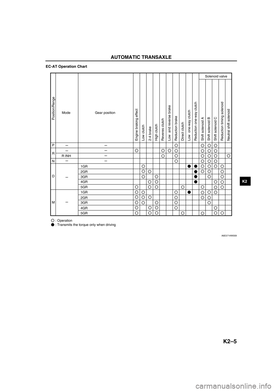
EC-AT Operation Chart
End Of Sie
Mode
P
R
R INH
1GR
2GR
3GR
4GR
5GR
1GR
2GR
3GR
4GR
5GR
: Operation
: Transmits the torque only when driving N
D
MGear position
Position/Renge
Engine braking effect
Low clutch
Low one-way clutch Low and reverse brake
Reduction brake
Reduction timing solenoid
Neutral shift solenoid Reduction one-way clutch
Shift solenoid A
Shift solenoid B
Shift solenoid C Direct clutch 2-4 brake
Solenoid valve
High clutch
Reveres clutch
A6E5714W009