MAZDA 626 1987 Workshop Manual
Manufacturer: MAZDA, Model Year: 1987, Model line: 626, Model: MAZDA 626 1987Pages: 1865, PDF Size: 94.35 MB
Page 301 of 1865

ASSEMBLY (AUXILIARY PARTS) 1 C
.JfTjQi
76G01C-209
76G01C-210
76G01C-211
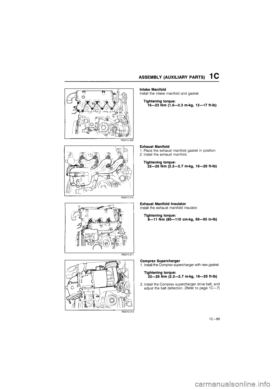
Intake Manifold
Install the intake manifold and gasket.
Tightening torque:
16โ23 N-m (1.6โ2.3 m-kg, 12โ17 ft-lb)
Exhaust Manifold
1. Place the exhaust manifold gasket in position.
2. Install the exhaust manifold.
Tightening torque:
22โ26 N-m (2.2โ2.7 m-kg, 16โ20 ft-lb)
Exhaust Manifold Insulator
Install the exhaust manifold insulator.
Tightening torque:
8โ11 N-m (80โ110 cm-kg, 69โ95 in-lb)
Comprex Supercharger
1. Install the Comprex supercharger with new gasket.
Tightening torque:
22โ26 N-m (2.2โ2.7 m-kg, 16โ20 ft-lb)
2. Install the Comprex supercharger drive belt, and
adjust the belt deflection. (Refer to page 1Cโ7)
76G01C-212
1Cโ89
Page 302 of 1865

1 C ASSEMBLY (AUXILIARY PARTS)
76G01C-213
76G01C-214
Comprex Supercharger Insulator
Install the comprex supercharger insulator.
Tightening torque:
8โ11 N-m (80โ110 cm-kg, 69โ95 in-lb)
Air Funnel Assembly
1. Install the air funnel assembly.
Tightening torque:
Bolt A: 19โ26
N
m
(1.9โ2.6 m-kg, 14โ19 ft-lb)
Bolt B: 3โ4
N
m
(35โ45 cm-kg, 30โ39 ft-lb)
2. Connect the actuator vacuum tube.
76G01C-215
Vacuum Pump
1. Install the vacuum pump with bracket.
Tightening torque:
37โ52 N-m (3.8โ5.3 m-kg, 27โ38 ft-lb)
2. Connect the oil pipe and hose.
Tightening torque:
12โ18 N-m (1.2โ1.8 m-kg, 104โ156 ft-lb)
3. Install the drive belt, and adjust the belt deflection.
(Refer to page 1Cโ7)
PCV Hose
Install the PCV hose.
I! Jfc)' j
.CSD water hose
ilJJM: !
76G01C-216
CSD Water Hose
1. Remove the engine from the engine hanger.
2. Tighten the oil pipe mounting bolts.
Bolt A: 8โ11 N-m
(80โ110 cm-kg, 69โ95 in-lb)
Bolt B: 12โ18 N-m
(1.2โ1.8 m-kg, 104โ156 ft-lb)
3. Install the CSD water hose.
Tightening torque:
37โ52 N-m (3.8โ5.3 m-kg, 27โ38 ft-lb)
1C-90
Page 303 of 1865

INSTALLATION 1C
INSTALLATION
TRANSAXLE ASSEMBLY
Assemble the transaxle to the engine in the sequence shown in the figure referring to the installation note.
37โ52 (3.8โ5. 27โ38
37-52 N m (3.8โ5.3 m-kg, 27โ38 ft-lb)
(80โ110 cm-kg, 69โ95 In-lb)
89โ117 N-m (9.1โ11.9 m-kg, 66โ86 ft-lb)
7-52 N-m (3.8โ5.3 m-kg, 27โ38 ft-lb)
76G01C-217
1. Transaxle
2. Clutch under cover
3. Gusset plate
4. Water pipe
5. Starter
Installation Note
Clutch under cover
Before installation, fill the notches with silicon as
shown in the figure.
76G01C-219
1Cโ91
Page 304 of 1865

1C INSTALLATION
ENGINE INSTALLATION
Install the engine and transaxle assembly.
Warning: Be sure the vehicle is securely supported.
Torque Specifications
67-93 N-m {6.6โ9.5 m-kg, 49โ69 ft-Sb)
8โ11 Nm (80โ110 cm-kg,โ 69โ95 in-lb)
85โ117 N m (8.7โ11.9 m-kg, 63โG6 ft-lb) Sโ11 N-m (80โ110em-kg, 69โ95 In-lb)
5โ7 N-m (50โ70 cm-kg, 43โ61 in-lb)
67โ93 N-m (6,8โ9,5 m-kg, 49โ69 ft-lb)
55โ80 N-m (5.6โ8.2 m-kg, 41โ59 ft-lb)
8โ11 N-m (80โ110 cm-kg, 69โ95 in-lb)
43โ62 N-m (4.3โ6.3 m-kg, 14โ22 ft-lb)
7โ10 N-m (70โ100 cm-kg, 60โ86 in-lb)
37โ52 N-m (3.6โ5.3 m-kg, 27โ38 ft-lb)
34โ49 N-m (3.5โ5.0 m-kg, 25โ36 ft-lb)
31โ40 N-m 9 (3.2-4.1 m-kg, 23โ30 ft-lb)
'8โ11 N-m (80โ110 cm-kg, 69โ95 in-lb)
19โ26 N-m (1.9โ2.6 m-kg, 14โ19 ft-lb)
29โ44 N-m (3.0โ4.5 m-kg, 22โ33 ft-lb)
43โ54 N-m (4.4โ5.5 m-kg, 32โ40 ft-lb)
-IS* 88โ118 N-m ^-(9.0โ12.0 m-kg, 65โ87 ft-lb) 8โ11 N-m (80โ110 cm-kg, 69โ95 In-lb)
86U01X-180
1Cโ92
Page 305 of 1865

INSTALLATION 1C
Engine Mount
Install the engine mount.
86U01X-181
Exhaust Pipe
1. Tighten exhaust pipe stay.
Tightening torque:
37โ52 Nm (3.8โ5.3 m-kg, 27โ38 ft-lb)
2. Install the exhaust pipe.
Tightening torque:
19โ26
N
m
(1.9โ2.6 m-kg, 14โ19 ft-lb)
(ยง): 34โ49 N-m
(3.5โ5.0 m-kg, 25โ36 ft-lb)
76G01C-218
Extension Bar
Install the extension bar to the transaxle.
Tightening torque:
31โ46 N-m (3.2โ4.7 m-kg, 23โ34 ft-lb)
Change Rod
Install the change rod to the transaxle.
Tightening torque:
16โ22 N-m (1.6โ2.3 m-kg, 12โ17 ft-lb)
76G01C-219
1Cโ93
Page 306 of 1865

1C INSTALLATION
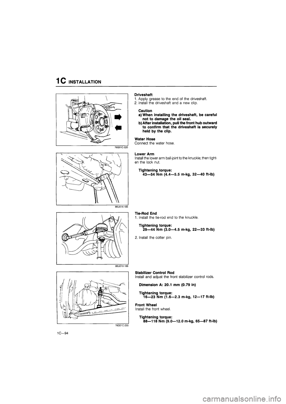
Driveshaft
1. Apply grease to the end of the driveshaft.
2. Install the driveshaft and a new clip.
Caution
a) When installing the driveshaft, be careful
not to damage the oil seal.
b) After installation, pull the front hub outward
to confirm that the driveshaft is securely
held by the clip.
Water Hose
Connect the water hose.
76G01C-220
Lower Arm
Install the lower arm ball-joint to the knuckle; then tight-
en the lock nut.
Tightening torque:
43โ54 N-m (4.4โ5.5 m-kg, 32โ40 ft-lb)
86U01X-185
Tie-Rod End
1. Install the tie-rod end to the knuckle.
Tightening torque:
29โ44 N-m (3.0โ4.5 m-kg, 22โ33 ft-lb)
2. Install the cotter pin.
86U01X-186
76G01C-255
Stabilizer Control Rod
Install and adjust the front stabilizer control rods.
Dimension A: 20.1 mm (0.79 in)
Tightening torque: 16โ23 N-m (1.6โ2.3 m-kg, 12โ17 ft-lb)
Front Wheel
Install the front wheel.
Tightening torque:
88โ118 N-m (9.0โ12.0 m-kg, 65โ87 ft-lb)
1Cโ94
Page 307 of 1865

INSTALLATION 1C
Heater Hose
Connect the heater hoses.
Note
Position the hose clamp in the original loca-
tion on the hose and squeeze the clamp lightly
with large pliers to ensure a good fit.
86U01X-221
Connector Location
Install each harness as shown in the figure.
1. Alternator
2. Boost air temperature sensor (RF-CX)
3. Heat gauge unit
4. Water thermo switch
5. Pick up coil
6. Glow cord
7. Front harness connector and ground
76G01C-222
8. Fuel cut valve
9. Oil pressure switch
10. Starter
11. Water temperature switch
12. Transaxle harness
13. Grounds
1Cโ95
Page 308 of 1865

1C INSTALLATION
76G01C-223
76G01C-224
76G01C-225
A/C Compressor
1. Install the A/C compressor.
Tightening torque:
37โ52 N-m (3.8โ5.3 m-kg, 27โ38 ft-lb)
2. Install the drive belt and adjust the belt deflection.
(Refer to page 1Cโ7)
Speedometer Cable
Install the speedometer cable.
Transaxle harness
Install the transaxle harness.
Clutch Release Cylinder
1. Set the pipe bracket in position.
Tightening torque:
19โ26 N-m (1.9โ2.6 m-kg, 14โ19 ft-lb)
2. Install the clutch release cylinder.
Tightening torque
19โ26 N-m (1.9โ2.6 m-kg, 14โ19 ft-lb)
No.4 Engine Mount
Install the No.4 engine mount.
Tightening torque:
(A): 55โ80 N-m
(5.6โ8.2 m-kg, 41โ59 ft-lb)
(|): 36โ54 N-m
(3.7โ5.5 m-kg, 27โ40 ft-lb)
ยฉ: 64โ89
N
m
(6.5โ9.1 m-kg, 47โ66 ft-lb)
67โ93 N-m
(6.8โ9.5 m-kg, 49โ69 ft-lb)
76G01C-226
1C-96
Page 309 of 1865

INSTALLATION 1C
76G01C-227
P/S Oil Pump
1. Install the P/S oil pump.
Tightening torque:
37โ52 Nm (3.8โ5.3 m-kg, 27โ38 ft-lb)
2. Install the P/S oil pump pully. (Refer to section 10)
Tightening torque:
55โ59 Nm (5.6โ6.0 m-kg, 41โ43 ft-lb)
3. Set the pipe bracket in position.
Tightening torque:
8โ11 Nm (80โ110 cm-kg, 69โ95 in-lb)
4. Install the drive belt and adjust the belt deflection.
(Refer to page 1Cโ7)
5. Install the drive belt cover.
Tightening torque:
8โ11
N
m (80โ110 cm-kg, 69โ95 in-lb)
76G01C-228
Fuel Hose
Install the fuel hose.
Note
Be careful of the red marks on the hose.
76G01C-229
76G01C-230
Intercooler Pipe and Hose
1. Install the intercooler pipe and hose.
Tightening torque:
19โ26 Nm (1.9โ2.6 m-kg, 14โ19 ft-lb)
2. Install the brake vacuum pipe.
Tightening torque:
8โ11
N
m (80โ110 cm-kg, 69โ95 in-lb)
3. Connect the brake vacuum hose securely and
squeeze the clamp lightly with pliers to ensure a
good fit.
1C-97
Page 310 of 1865

1C INSTALLATION
Radiator
1. Install the radiator and cooling fan,
Tightening torque:
8โ11 Nm (80โ110 cm-kg, 69โ95 in-lb)
2. Connect the radiator harness.
76G01C-213
3. Connect the upper and lower radiator hoses.
Note
a) Position the hose clamp in the original lo-
cation on the hose.
b) Squeeze the clamp lightly with large pliers
to ensure a good fit.
4. Install the solenoid valve and ground.
Tightening torque:
8โ11
N
m (80โ110 cm-kg, 69โ95 in-lb)
76G01C-232
Air Cleaner Assembly
Install the air cleaner assembly.
Tightening torque:
16โ27 Nm (1.6โ2.8 m-kg, 12โ20 ft-lb)
76G01C-233
Battery and Battery Carrier
1. Install the battery carrier.
Tightening torque:
Bolt A: 31โ40
N
m
(3.2โ4.1 m-kg, 23โ30 ft-lb)
Bolt B: 8โ11 N-m
(80โ110 cm-kg, 69โ95 in-lb)
2. Install the battery tray and battery.
Tightening torque:
5โ7 N-m (50โ70 cm-kg, 43โ61 in-lb)
76G01C-226
1C-98