MAZDA 626 1987 Workshop Manual
Manufacturer: MAZDA, Model Year: 1987, Model line: 626, Model: MAZDA 626 1987Pages: 1865, PDF Size: 94.35 MB
Page 771 of 1865

5 STARTER (DIESEL ENGINE, 2.0 KW TYPE)
(S) terminal Switch (K)
(B) terminal
Amp. meter
Voltmeter
4BG05X-105
No-load Test
1. After adjusting the pinion gap, form a test circuit
with a voltmeter and an ammeter.
Note
Use wires as thick as possible and tighten
each terminal fully.
2. Close switch "K" to run the starter.
If
the voltmeter
and ammeter show the following values while the
starter is running, it is normal.
Battery voltage: 11.5 volts
Current: 120 amperes or less
Gear shaft speed: at 4,000 or more
3. If any abnormality is noted, check it according to
"INSPECTION"
5—65
Page 772 of 1865

5 STARTER (DIESEL ENGINE, 2.0 KW TYPE)
STARTER (DIESEL
ENGINE, 2.2
KW TYPE)
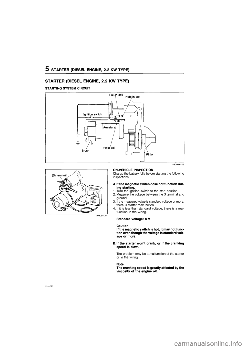
STARTING SYSTEM CIRCUIT
4BG05X-106
76G05X-060
ON-VEHICLE INSPECTION
Charge the battery fully before starting the following
inspections.
A. If the magnetic switch dose not function dur-
ing starting.
1. Turn the ignition switch to the start position.
2. Measure the voltage between the S terminal and
ground.
3.
If
the measured value is standard voltage or more,
there is starter malfunction.
4. If it is less than standard voltage, there is a mal-
function in the wiring.
Standard voltage: 8 V
Caution
If the magnetic switch is hot, it may not func-
tion even though the voltage is standard volt-
age or more.
B.lf the starter won't crank, or if the cranking
speed is slow.
The problem may be a malfunction of the starter
or in the wiring.
Note
The cranking speed is greatly affected by the
viscosity of the engine oil.
5—66
Page 773 of 1865

5 STARTER (DIESEL ENGINE, 2.0 KW TYPE)
REMOVAL AND INSTALLATION
Removal is as follows:
1. Disconnect the negative battery cable.
2. Disconnect the wiring from the starter.
3. Remove the starter.
Install in the reverse order of removal.
Tightening torque:
Bolts 64—89 N-m
(6.5—9.1 m-kg, 47—66 ft-lb)
B terminal 9.8—11.8 N-m
(1.0—1.2 m-kg, 87—104 in-lb)
76G05X-046
DISASSEMBLY AND ASSEMBLY
1. Disassemble in the numbered order shown in the figure.
2. Assembly in the reverse order of disassembly.
4BG05X-107
1. Magnetic switch 7. Lever
2. Rear cover 8. Cover
3. Brush-holder assembly 9. Drive pinion and over-running
4. Yoke clutch assembly
5. Armature 10. Reduction gear
6. Front housing 11. Center bracket
5—67
Page 774 of 1865

5 STARTER (DIESEL ENGINE, 2.2 KW TYPE)
Disassembly
1. Remove the magnetic switch.
4BG05X-108
2. Remove the rear housing.
4EG05X-069
3. Using radio pliers or a similar tool, raise the posi-
tive (+) side brush spring, and remove the brush.
36G05X-032
4. Remove the brush holder assembly and the ar-
mature.
36G05X-033
5—68
Page 775 of 1865

STARTER (DIESEL ENGINE, 2.2 KW TYPE) 5
36G05X-034
36G05X-035
36G05X-036
5. Remove the front cover, and remove the lever and
springs (two).
6. Separate the yoke and center bracket.
7. Remove the cover and pull out the snap ring and
washer.
8. Remove the pinion, over-running clutch assembly
and reduction gear from the center bracket.
36G05X-037
5-69
Page 776 of 1865

5 STARTER (DIESEL ENGINE, 2.2 KW TYPE)
Reduction gear
Adjusting washer
-Pinion shaft
-Thrust gap
-Snap ring
-Washer
Washer bracket
4BG05X-109
4BG05X-110
4BG05X-111
Assembly (main point)
Pinion shaft play
1. Measure the thrust gap by moving the pinion shaft
axial direction.
Standard play: Less than 0.5 mm (0.02 in)
2. Adjust the play with the adjusting washer.
Lever installation
Install the lever as shown in figure.
Rear bracket installation
Align the matching marks when assembling the rear
bracket.
Greasing
When disassembling or assembling the starter,
grease each sliding part, gear and bearing.
(1) Armature shaft gear
(2) Reduction gear
(3) Ball bearings (both ends of armature)
(4) Bearing box of rear bracket
(5) Snap ring of pinion shaft
(6) Sleeve bearing, pinion lever sliding part, others
4BG05X-112
5—70
Page 777 of 1865

STARTER (DIESEL ENGINE, 2.2 KW TYPE) 5
4BG05X-113
4BG05X-080
Adjustment of pinion gap
1. Disconnect the wiring from terminal (M).
2. Apply battery power to the terminal (S) and ground
the starter motor body, the pinion will eject outward
and then stop.
3. Measure the clearance (pinion gap) between the
pinion and the stopper.
Note
Be careful not to let electricity flow continu-
ously for more than 10 seconds.
Pinion gap: 0.5—2.0 mm (0.020—0.079 in)
4. If the pinion gap is not within the specified range,
make the adjustment by increasing or decreasing
the number of washers used between the magnetic
switch and the drive housing. The gap will become
smaller if the number of washers is increased.
Caution
Do not use the washers more than plates.
INSPECTION
Armature Coil
1. Ground of the armature coil
Check for continuity between the commutator and
the core by using a circuit tester. Replace the ar-
mature if there is continuity.
4BG05-081
2. Vibration of the commutator
Plate the armature on V blocks, and measure the
vibration by using a dial gauge. If the vibration is
Limit or more, repair so that is standard by using
a lathe, or replace the armature.
Standard vibration: 0.05 mm (0.002 in)
Limit: 0.4 mm (0.018 in)
Note
Before checking, be sure than there is no play
in the bearings.
4BG05X-Q82
5-71
Page 778 of 1865

5 STARTER (DIESEL ENGINE, 2.2 KW TYPE)
4BG05X-115
4BG05X-085
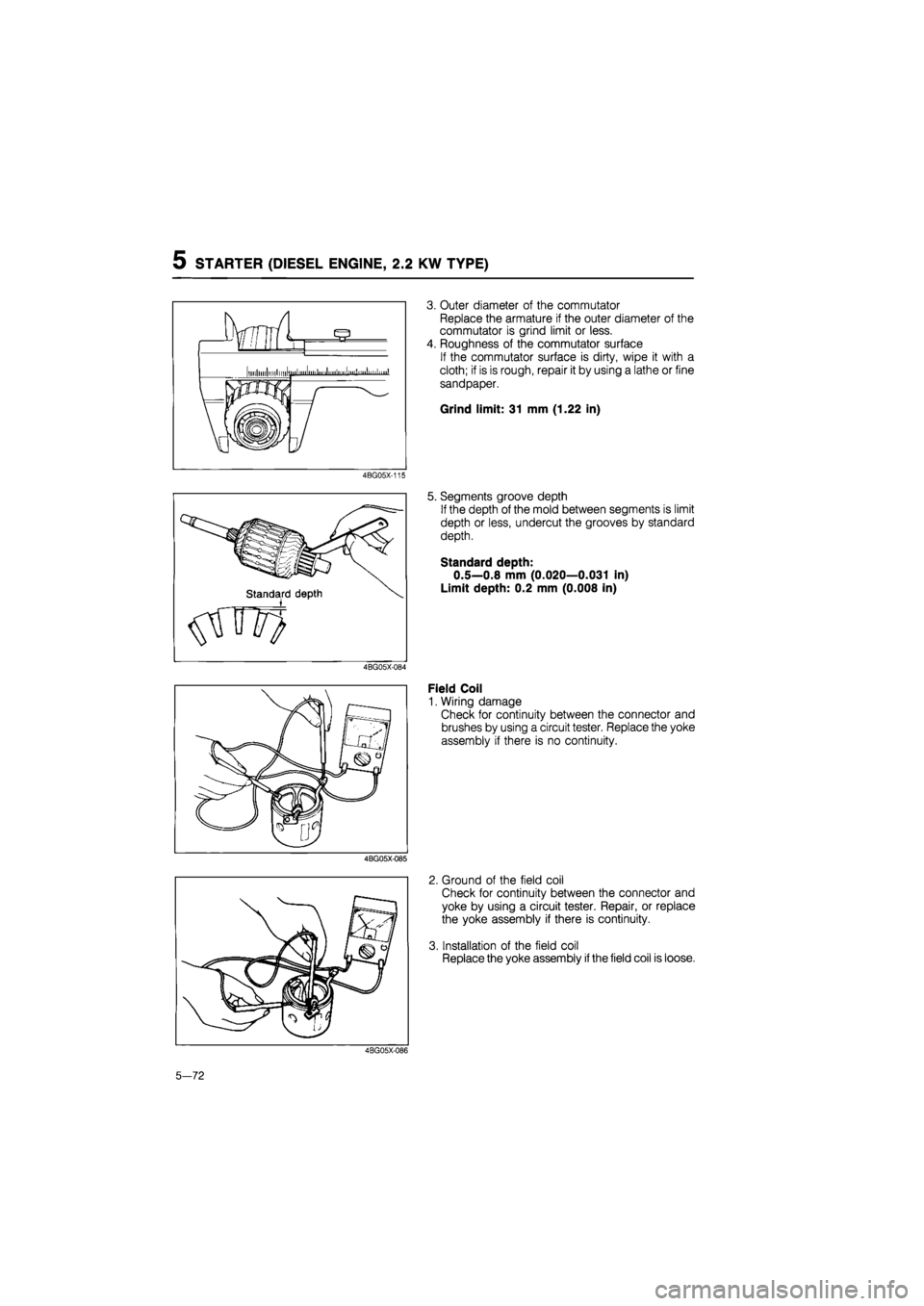
3. Outer diameter of the commutator
Replace the armature if the outer diameter of the
commutator is grind limit or less.
4. Roughness of the commutator surface
If the commutator surface is dirty, wipe it with a
cloth; if is is rough, repair it by using a lathe or fine
sandpaper.
Grind limit: 31 mm (1.22 in)
5. Segments groove depth
If the depth of the mold between segments is limit
depth or less, undercut the grooves by standard
depth.
Standard depth:
0.5—0.8 mm (0.020—0.031 in)
Limit depth: 0.2 mm (0.008 in)
Field Coil
1. Wiring damage
Check for continuity between the connector and
brushes by using a circuit tester. Replace the yoke
assembly if there is no continuity.
2. Ground of the field coil
Check for continuity between the connector and
yoke by using a circuit tester. Repair, or replace
the yoke assembly if there is continuity.
3. Installation of the field coil
Replace the yoke assembly
if
the field coil is loose.
4BG05X-086
5-72
Page 779 of 1865

STATRER (DIESEL ENGINE, 2.2 KW TYPE) 5
11*mm S (0.433 in)
A
A 18 mm
(0,709)
Brush and Brush Holder
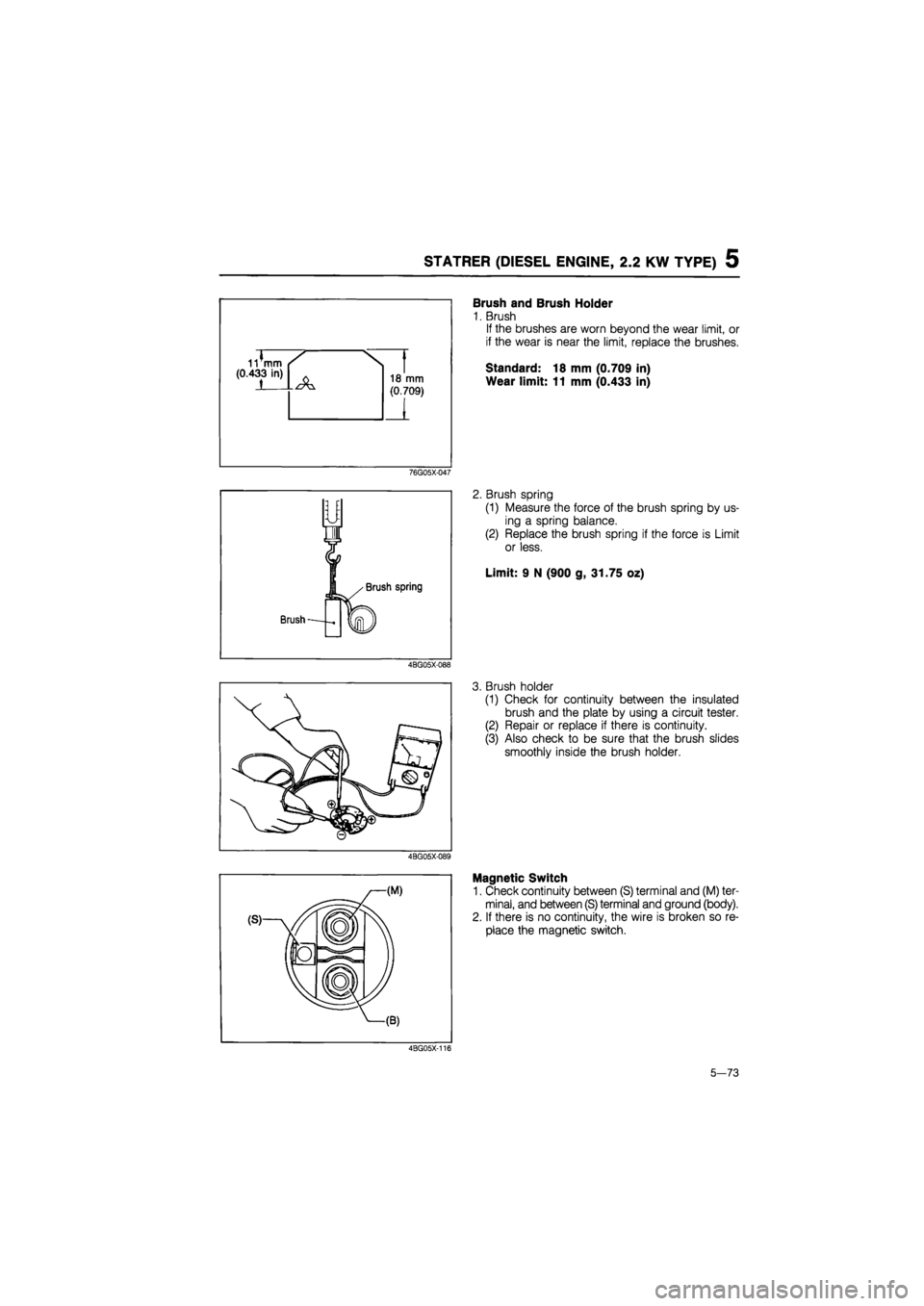
1. Brush
If the brushes are worn beyond the wear limit, or
if the wear is near the limit, replace the brushes.
Standard: 18 mm (0.709 in)
Wear limit: 11 mm (0.433 in)
76G05X-047
2. Brush spring
(1) Measure the force of the brush spring by us-
ing a spring balance.
(2) Replace the brush spring if the force is Limit
or less.
Limit: 9 N (900 g, 31.75 oz)
4BG05X-088
3. Brush holder
(1) Check for continuity between the insulated
brush and the plate by using a circuit tester.
(2) Repair or replace if there is continuity.
(3) Also check to be sure that the brush slides
smoothly inside the brush holder.
4BG05X-089
Magnetic Switch
1. Check continuity between (S) terminal and (M) ter-
minal, and between (S) terminal and ground (body).
2. If there is no continuity, the wire is broken so re-
place the magnetic switch.
4BG05X-116
5-73
Page 780 of 1865

5 STARTER (DIESEL ENGINE, 2.2 KW TYPE)
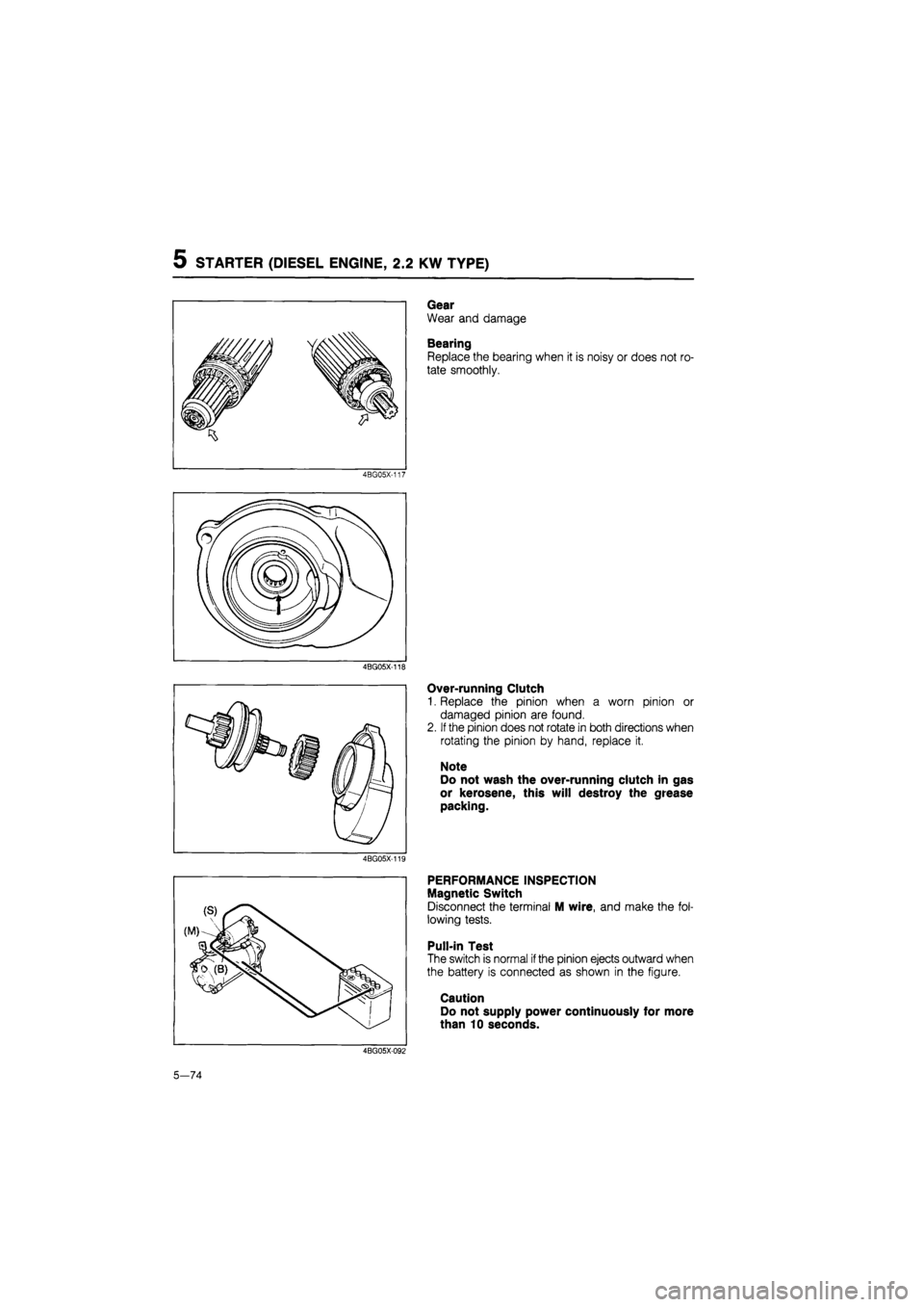
Gear
Wear and damage
Bearing
Replace the bearing when it is noisy or does not ro-
tate smoothly.
4BG05X-117
4BG05X-118
Over-running Clutch
1. Replace the pinion when a worn pinion or
damaged pinion are found.
2.
If
the pinion does not rotate in both directions when
rotating the pinion by hand, replace it.
Note
Do not wash the over-running clutch in gas
or kerosene, this will destroy the grease
packing.
4BG05X-119
PERFORMANCE INSPECTION
Magnetic Switch
Disconnect the terminal M wire, and make the fol-
lowing tests.
Pull-in Test
The switch is normal
if
the pinion ejects outward when
the battery is connected as shown in the figure.
Caution
Do not supply power continuously for more
than 10 seconds.
4BG05X-092
5—74