ignition MAZDA PROTEGE 1992 Workshop Manual
[x] Cancel search | Manufacturer: MAZDA, Model Year: 1992, Model line: PROTEGE, Model: MAZDA PROTEGE 1992Pages: 1164, PDF Size: 81.9 MB
Page 918 of 1164

T
I WARNING SYSTEM
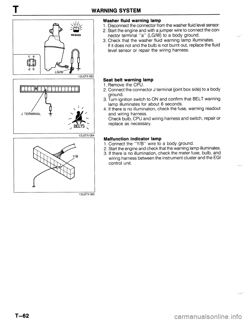
Washer fluid warning lamp
1. Disconnect the connector from the washer fluid level sensor.
2. Start the engine and with a jumper wire to connect the con-
nector terminal “a” (LGIW) to a body ground.
3. Check that the washer fluid warning lamp illuminates.
If it does not and the bulb is not burnt out, replace the fluid
level sensor or repair the wiring harness.
13UOTX-08
_-
1 /
J TERMINAL -
13UOTX-08
13UOTX-08
Seat belt warning lamp
1, Remove the CPU.
2. Connect the connector J terminal (joint box side) to a body
ground.
3. Turn ignition switch to ON and confirm that BELT warning
lamp illuminates for about 6 seconds.
4. If there is no illumination, check the fuse, warning readout
and wiring harness.
Check bulb, CPU and wiring harness and switch, repair or
replace as necessary.
Malfunction indicator lamp
1, Connect the “Y/B” wire to a body ground.
2. Start the engine and check that the warning lamp illuminates.
3. If there is no illumination, check the meter fuse, bulb, and
wiring harness between the instrument cluster and the EGI
control unit.
T-62
Page 923 of 1164

INSTRUMENT CLUSTER T
Symptom: Water temperature gauge does not operate.
9MUOTX-072
W/ TACHO W/O TACHO
OSUOTX-111
0
23UOTX-041
WI TACHO
W/O TACHO
9MUOTX-076
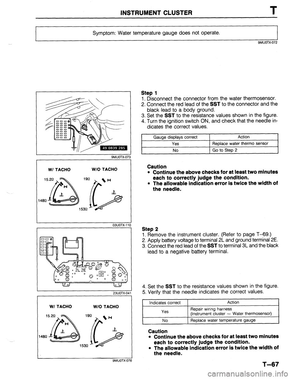
Step 1
1. Disconnect the connector from the water thermosensor.
2. Connect the red lead of the
SST to the connector and the
black lead to a body ground.
3. Set the
SST to the resistance values shown in the figure.
4. Turn the ignition switch ON, and check that the needle in-
dicates the correct values.
Gauge displays correct Action
Yes Replace water therm0 sensor
No Go to Step 2
Caution
l Continue the above checks for at least two minutes
each to correctly judge the condition.
l The allowable indication error is twice the width of
the needle.
Step 2
1. Remove the instrument cluster. (Refer to page T-69.)
2. Apply battery voltage to terminal 2L and ground terminal 2E.
3. Connect the red lead of the
SST to terminal 3L and the black
lead to a negative battery terminal.
4. Set the
SST to the resistance values shown in the figure.
5. Verify that the needle indicates the correct values.
Indicates correct
Yes Action
Repair wiring harness
(instrument cluster - Water thermosensor)
I--~ No I ReDlace water temperature gauge
I
Caution
l Continue the above checks for at least two minutes
each to correctly judge the condition.
l The allowable indication error is twice the width of
the needle.
T-67
Page 924 of 1164

T INSTRUMENT CLUSTER
Symptom: Fuel gauge does not operate.
SMUOTX-077 -_d
,
1
OBUOTX-186
W/ TACHO W/O TACHO
7R 7cl
9MUOTX-079
23UOTX-04:
WI TACHO W/O TACHO
7Q 7cl
Step 1
1. Disconnect the connector from the fuel gauge sender unit.
2. Connect the red lead of the SST to the terminal-wire (Y) and
the black lead to a body ground.
3. Set the SST to the resistance values shown in the figure.
4. Turn the ignition switch ON, and verify that the needle indi-
cates the correct values.
Indicates correct Action
Yes Replace fuel gauge sender unit (in fuel tank)
/
No Go
to Step 2
Caution
l Continue the above checks for at least two minutes
each to correctly judge the condition.
l The allowable indication error is twice the width of
the needle.
Step 2
1. Remove the instrument cluster. (Refer to page T-69.)
2. Apply battery voltage to terminal 2L and ground terminal 2E.
3. Connect the red lead of the SST to terminal 1C and the
black lead to a negative battery terminal.
4. Set the SST to the resistance values shown in the figure.
5. Verify that the needle indicates the correct values.
Indicates correct Action
Yes Repair wiring harness
(Instrument cluster - fuel gauge sender unit)
No Replace fuel gauge sender unit
Caution
. Continue the above checks for at least two minutes
each to correctly judge the condition.
l The allowable indication error is twice the width of
the needle. .-/
Page 928 of 1164

T INSTRUMENT CLUSTER
I
23UOTX-045
W/ TACHO WI0 TACHO
QMUOTX-08!
03UOTX- 11,
03UOTX.11
OBUOTX-
T-72
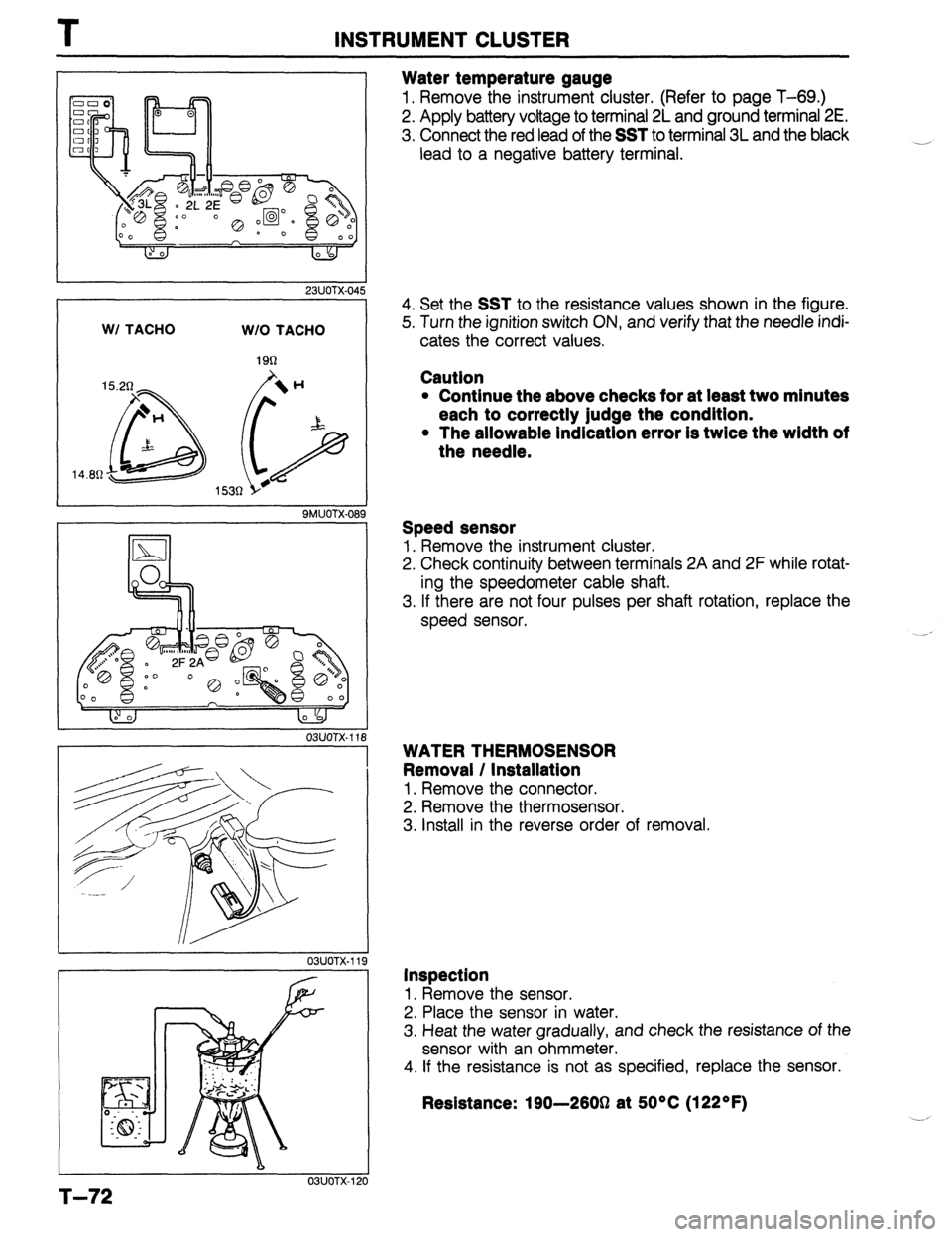
Water temperature gauge
1. Remove the instrument cluster. (Refer to page T-69.)
2. Apply battery voltage to terminal 2L and ground terminal 2E.
3. Connect the red lead of the SST to terminal 3L and the black
lead to a negative battery terminal.
____,
4. Set the SST to the resistance values shown in the figure.
5. Turn the ignition switch ON, and verify that the needle indi-
cates the correct values.
Cautlon
l Continue the above checks for at least two minutes
each to correctly judge the condition.
l The allowable indication error is twice the width of
the needle.
Speed sensor
1. Remove the instrument cluster.
2. Check continuity between terminals 2A and 2F while rotat-
ing the speedometer cable shaft.
3. If there are not four pulses per shaft rotation, replace the
speed sensor.
WATER THERMOSENSOR
Removal / Installation
1. Remove the connector.
2. Remove the thermosensor.
3. Install in the reverse order of removal.
Inspection 1.
Remove the sensor.
2. Place the sensor in water.
3. Heat the water gradually, and check the resistance of the
sensor with an ohmmeter. 4.
If the resistance is not as specified, replace the sensor.
Resistance: 190-2603 at 5O*C (122OF)
Page 937 of 1164

CRUISE CONTROL SYSTEM T
L 23UOTX-05
Condition Code Numbers
Self-diagnosis of malfunction
The test light will flash if a malfunction is present.
Inspection Procedure
Self-diagnosis of malfunction
1. Locate the cruise control connector.
2. Connect a 1.4W test light between terminals f and d, with
connector attached to control unit.
Note
l There is no wire in terminal d of the connector. Push
the test light through the connector and touch the
corresponding pin on the control unit.
3. Turn the ignition switch to ON.
4. Turn the cruise control on by pressing the MAIN switch. (The
MAIN indicator lamp will come ON.)
5. Press and hold the RESUMElACCEL switch for more than
three second.
6. The test light will illuminate for 3 seconds and go out for
2 seconds.
7. The self-diagnostic system is activated and the test light will
flash if a problem is present.
8. Make note of the condition code number(s).
(Refer to the chart at the bottom of the page).
9. After retrieving the code(s), drive the vehicle at more than
16 km/h (lOmph), or press the MAIN switch to deactivate
self-diagnosis. (The MAIN indicator lamp will go OFF.)
Note
l The cruise control system will not operate when in
the self-diagnosis mode.
Pattern of output signal
(Test light)
ON
OFF ON
GFF
,“r,- ON
OFF Note
23UOTX-05
l
If there is more than one malfunction, the code numbers will be indicated in numerical order.
T-81 Code
No.
01
05 Possible Cause Action
Defective wiring (Actuator-Cruise control
unit, Stoplight switch-Cruise control unit)
Defective actuator
Defective stoplight switch (For cruise)
STOP fuse blown
Defective wiring (Fuse - Cruise control
unit)
Both stoplight switches (for vehicle and
cruise) are ON simultaneously
Defective SET/COAST. or RESUME/ Inspect cruise control switch
ACCEL switch (Refer to page T-21)
Defective cruise control unit Repair harness
Inspect actuator
(Refer to page T-87)
Inspect stoplight switch
(Refer to page T-87)
Replace fuse
Repair harness
Inspect stoplight switches
(Refer to pages T-47 and
T-87)
Go to troubleshooting
(Refer to page T-83)
Page 938 of 1164

CRUISE CONTROL SYSTEM
I
23UOTX-056
1 23UOTX-057
Inspection Procedure
Quick inspection of cruise control system
1. Locate the cruise control connector.
2. Connect a 1.4W test light between terminals f and d, with
connector attached to control unit. -1
Note
l There is no wire in terminal d of the connector. Push
the test light through the connector and touch the
corresponding pin on the control unit.
3. Turn the ignition switch to ON.
4. Verify that the MAIN switch is OFF. (The MAIN indicator lamp
is OFF.)
5. Press the RESUMElACCEL switch and the MAIN switch
simultaneously to activate the system inspection. (The MAIN
indicator lamp will come ON.)
6. Operate each switch as described below and verify the oper-
ation codes.
7. Press the MAIN switch to deactivate the system inspection.
(The MAIN indicator lamp will go OFF.)
Note
l The cruise control system will not operate when in
the self-diagnosis mode.
Operation Code Numbers
Inspection of cruise control system
The test light will flash if the system is operating correctly. If the light fails to flash, inspect the system.
Note
l Shift the selector lever to D or R range before operating the inspection. (For ATX)
l Shift to the gear except the neutral position. (For MTX)
Procedure
Press SET/COAST switch Pattern of output signal Code
(Test light) No. Actlon to inspect ON
n II 21 Inspect cruise control switch
(Refer to page T-21)
OFF
Press RESUMElACCEL switch
ON
n 22 inspect cruise control switch
(Refer to page T-21)
OFF
Depress brake pedal
ON
n ml 31 Inspect stoplight switches
(Refer to pages T-47 and
OFF T-88)
Turn ignition switch to ON and shift the ON 35 Inspect inhibitor switch
selector lever to P or N range (For ATX) (Refer to Section K) or clutch
Depress clutch pedal (For MTX) switch (Refer to Section F)
OFF
Drive vehicle above 40 km/h (25 mph) ON 37 Inspect speed sensor or wire
harness
OFF
I
1
. . . _
T-82
Page 940 of 1164

1
CRUISE CONTROL SYSTEM
Can’t set or control the speed
I
.
Check meter 15A and stop 20
I Short circuit (broken wire) OK
Turn ignition switch to ON and push on main switch
Check for battery voltage on Y wire of cruise control
unit connector NO
Check cruise control main switch (Refer to page T-21)
3 OK
Check for OV on B wire of cruise control unit connector
I Faulty grounding of cruise control unit
I() OK
Is cruise control unit (m) terminal voltage OK?
(Refer to page T-86)
t Check stoplight switch 1 (Refer to page T-52) p OK
Is cruise control unit (h) terminal voltage OK?
(Refer to page T-86) NG Check stoplight switch 2 (Refer to page T-87)
$4 1 OK
Is cruise control unit (g) terminal voltage OK?
(Refer to page T-86)
p OK
Check EC-AT control unit (Refer to Section K) 1
Is cruise control unit (P) terminal voltage OK?
(Refer to page T-86) Check speed sensor
Is cruise control unit (n) terminal voltage OK?
(Refer to page T-86) Check cruise control switch (Refer to page T-21)
0 OK
Is cruise control unit (a, b, c, o) terminal voltage OK?
(Refer to page T-86)
9 OK Check actuator (Refer to page T-87)
Is cruise control unit (e) terminal voltage OK?
(Refer to page T-86) 1
NC2 I
I ..- - Check cruise control main switch (Refer to page T-21)
I I
I 4
e OK
I
Is cruise control unit (9 terminal voltage OK?
(Refer to page T-86) NO i
Cont’d
T-84
Page 942 of 1164

I
CRUISE CONTROL SYSTEM
s q 0 m
9 e c a
t rpn i j
h
f d b
*
Inspection
Cruise control unit
1. Connect a voltmeter between cruise control unit and ground.
2. Turn the ignition switch ON and check the terminal voltages
as described below.
03UOTX-146
VB: Batterv voltage
c (Output) Actuator
I ov
Approx. 9V
e (Input)
I Cruise control main
I
VB switch (NC)
f (Input)
9 Wv-4 Cruise control main
switch (N.0)
EC-AT control unit
VB
V0
h (Output) (only ATX)
Stoplight switch 2 (N.C) Approx. 9V
i (hW Note I
Inhibitor switch (ATX)
I ov
Approx. 5V Disconnect t
EGI control
Clutch switch (MTX)
ov unit connector Approx. 5V
Cruise control switch
(Set/coast switch) V0
Approx. 5V unit connector
a
S I Battery
I VI3 t
1 Ground I ov Procedure
Ignition switch ON
Main switch ON
Ignition switch ON
Main switch ON
ignition switch ON
Main switch ON
Ignition switch ON
Main switch ON
Ignition switch ON
Main switch ON
“N” or “P” range and main switch ON
Other range and main switch ON
Clutch pedal depressed and main switch ON
Main switch ON
Horn switch OFF
Ignition switch ON
Brake pedal depressed
Main switch ON
While pushing the resumelaccel switch after main switch
ON
Main switch ON
While pushing the set/coast switch after main switch ON
Main switch ON
Brake pedal depressed
While rotating the rear tire
Constant
Constant
23UOTX-OE $0
‘,.__,
_ _-_,’
T-86
Page 962 of 1164

U TROUBLESHOOTING GUIDE
Symptom: Blower motor does not operate.
Normal operation of blower motor
Blower motor speed is controlled by the blower switch and a resistor assembly in the blower unit.
When the blower switch is in the OFF position, the motor ground circuit is open and the blower motor does
not operate. When the switch is in the first (Low) position, current flow from the blower motor is restricted
by the three resistors in the resistor assembly, and the blower motor turns at low speed.
Changing the blower switch to the second (Mid), third (High), or fourth (Super-high) positions causes the
circuit resistance to decrease, and the blower motor speed to become correspondingly faster.
03uoux-005
. HEATER 30A
CIRCUIT
BREAKER
RED BUTTON
23UOUX-01
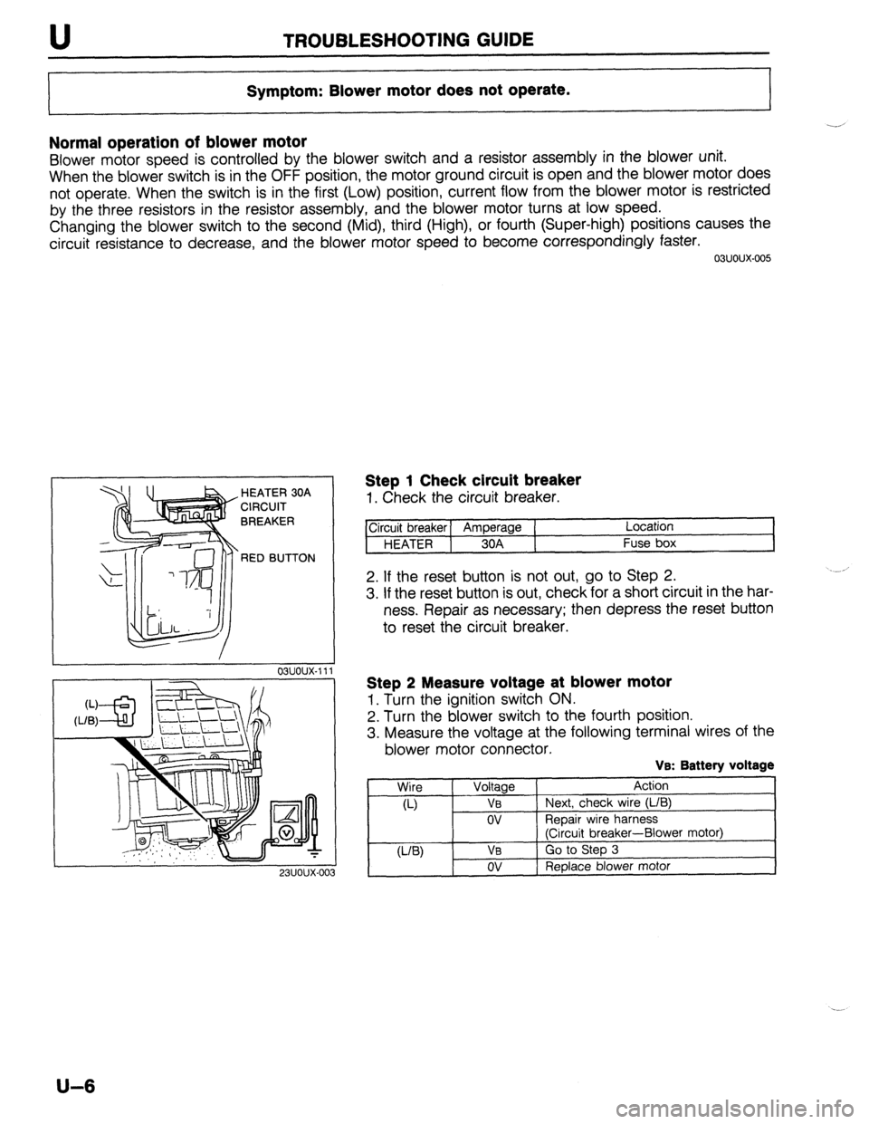
Step 1 Check circuit breaker
1. Check the circuit breaker.
ircuit breaker] Amperage ( Location
HEATER 1 30A Fuse box
2. If the reset button is not out, go to Step 2.
3. If the reset button is out, check for a short circuit in the har-
ness. Repair as necessary; then depress the reset button
to reset the circuit breaker.
Step 2 Measure voltage at blower motor
1. Turn the ignition switch ON.
2. Turn the blower switch to the fourth position.
3. Measure the voltage at the following terminal wires of the
blower motor connector.
VB: Battery voltage
Wire
Voltage Action
a-) VB Next, check wire (L/B)
ov ReDair wire harness
(Ciicuit breaker-Blower motor)
U-W VB Go to Step 3
ov Replace blower motor
U-6
Page 963 of 1164

TROUBLESHOOTING GUIDE U
23UOUX-004
Step 3 Measure voltage at resistor assembly
1. Turn the ignition switch ON.
2. Turn the blower switch OFF and verify that the A/C switch
is OFF.
3. Measure the voltage at the following terminal wires of the
resistor assembly.
VB: Battery voltage
Wire Voltage Action
u-w V0 Next, check wire (L/R)
ov Replace resistor assembly
0-w V0 Next, check wire (L)
ov Reolace resistor assembly
(L)
(L/Y) V0 Next, check wire (L/Y)
ov Replace resistor assembly
VB Go to Step 4
ov Replace resistor assembly
I
23UOUX-005
-.I
Step 4 Measure voltage at blower switch
1. Turn the ignition switch ON.
2. Turn the blower switch to the fourth position.
3. Measure the voltage at the following terminal wire of the
blower switch connector.
Ve: Battery voltage
Wire Voltage Action
W ov Go to Step 5
VB Repair wire harness
(Blower switch-Body ground)
1
23UOUX-00 6
Step 5 Measure voltage at blower switch
1. Turn the ignition switch ON.
2. Turn the blower switch and A/C switch OFF.
3. Measure the voltage at the following terminal wires of the
blower switch connector.
Ve: Battery voltage
Wire Voltage
WV ov
VB
(L/R) - OV
VB
u-) ov
VB
(L/Y) ov
VB Action
Repair wire harness
(Resistor assembly-Blower switch)
Next, check wire (L/R)
Reparr wire harness
(Resistor assembly-Blower switch)
Next, check wire (L)
Repair wire harness
(Resistor assembly-Blower switch)
Next, check wire (L/Y)
Repair wire harness
(Resistor assembly-Blower switch)
Replace blower switch
u-7