MAZDA PROTEGE 1992 Workshop Manual
Manufacturer: MAZDA, Model Year: 1992, Model line: PROTEGE, Model: MAZDA PROTEGE 1992Pages: 1164, PDF Size: 81.9 MB
Page 501 of 1164

TRANSAXLE Jl
1. Wheel and tire
2. Splash shield
3. Air hose and resonance chamber
4. Battery
5. Battery carrier
6. Speedometer cable
7. Back-up light switch connector
8. Neutral switch connector
9. Ground
10. Starter
11. Extension bar
12. Control rod
13. Engine mount member
Removal Note . . . . . . . . . . . . . . . . . . . . . . 14. Exhaust pipe
15. Engine mount No.2
16. Clutch release cvlinder
Removal Note . . . . . . . . . . . . . . . . . . . . . . . . . . . page Jl-1 1
17. Tie-rod end
Removal Note . . . . . . . . . . . . . . . . . . . . . . . . page Jl-12
18. Stabilizer (BP SOHC)
19. Driveshaft
Removal Note . . . . . . . . . . . . . . . . . . . . . . . . . . . page Jl-12
20. Engine mount No.4
21. Transaxle
Removal Note . . . . . . . . . . . . . . . . . . . . . . . . . . . page Jl-12
page Jl-11
03UOJl-012
Removal Note
Engine mount member
1. Suspend the engine with the SST and remove the engine
mount member.
03UOJ2-015 Clutch release cylinder
Caution
l Do not damage the clutch pipe.
1. Remove the bolts shown.
2. Lay aside the clutch release cylinder and the clutch pipe
when removing the transaxle.
03UOJl-013
,Jl-11
Page 502 of 1164

Jl TRANSAXLE
L
r
r
23UOJl-002
03lJOJl-016
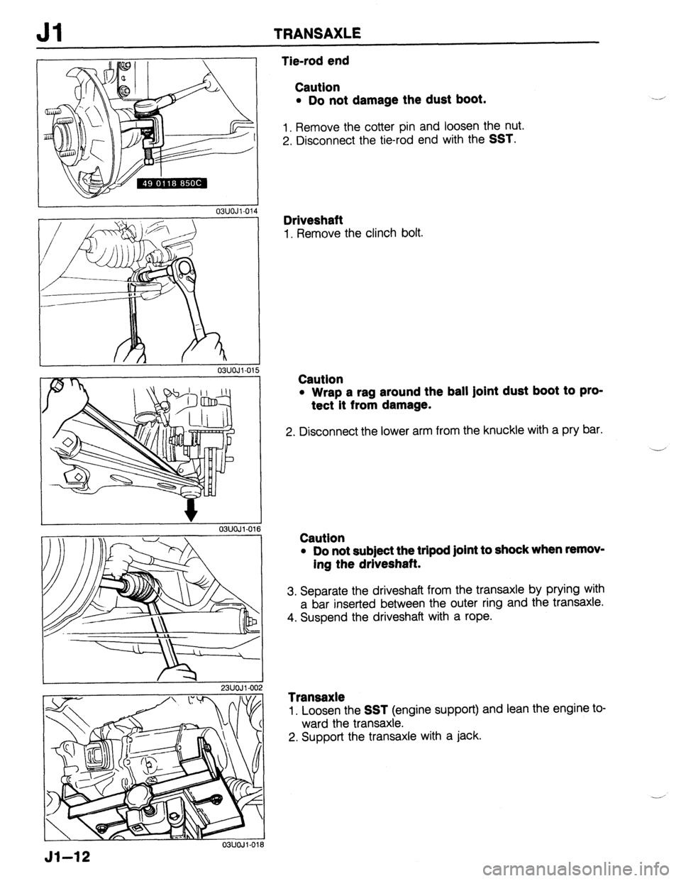
Tie-rod end
Caution
l Do not damage the dust boot.
1. Remove the cotter pin and loosen the nut.
2. Disconnect the tie-rod end with the
SST.
Driveshaft
1. Remove the clinch bolt.
Caution
l Wrap a rag around the ball Joint dust boot to pro-
tect it from damage.
2. Disconnect the lower arm from the knuckle with a pry bar.
.-’
Caution
l Do not sub]ect the tripod joint to shock when remov-
ing the driveshaft.
3. Separate the driveshaft from the transaxle by prying with
a bar inserted between the outer ring and the transaxle.
4. Suspend the driveshaft with a rope.
Transaxle
1. Loosen the SST (engine support) and lean the engine to-
ward the transaxle.
2. Support the transaxle with a jack.
Jl-12
Page 503 of 1164

TRANSAXLE Jl
03UOJl-019
3. Remove the transaxle mounting bolts.
4. Remove the transaxle.
Jl-13
Page 504 of 1164

Jl TRANSAXLE
DISASSEMBLY
Precaution
1. Clean the transaxle exterior thoroughly with a steam cleaner or cleaning solvent before disassembly.
2. Clean the removed parts (except sealed bearings) and all sealing surfaces with cleaning solvent, and dry
with compressed air. Clean out all holes and passages with a compressed air, and check that there are
no obstructions.
3. Wear eye protection when using compressed air to clean components.
03UOJ2-020 5th/Reverse Gear and Housing Parts
1. Measure the thrust clearance between 5th gear and the transaxle case, referring to Preinspection.
2. Disassemble in the order shown in the figure, referring to Disassembly Note.
L
CLIP<
REPLACE
09 ROLL PI/N,
REPLACE
03UOJl-021
Jl-14 3
Page 505 of 1164

TRANSAXLE Jl
1, Rear cover
2. Locknut (Primary shaft)
Disassembly Note .,......,,.,......... page Jl-15
3. Stop plate
4. Locknut (Secondary shaft)
Disassembly Note ,..,....,,.,......... page Jl-15
5. 5th shift fork
6. Clutch hub assembly (5th)
Inspection . . . . . . . . . . . . . . . . ..*............... page J l-29
7. Synchronizer ring (5th)
Inspection . . . . . . . . . . . . . . . . . . . . . . . . . . . . . . . . . . page Jl-27
8. 5th gear
Inspection . . . . . . . . . . . . . . . . . . . . . . . . . . . . . . . . . . page Jl-28
9. Gear sleeve
Inspection . . . . . . . . . . . . . . . . ..*...*........... page Jl-28
10. Secondary 5th gear
11. Lock bolt and washer
12. Back-up light switch
13. Neutral switch
14. Transaxle case assembly
15. Magnet
16. Reverse idler shaft
17. Reverse idler gear
Inspection.. . . , . . . . . . . . . . . . . . . , , . , . . . . . . . . . . page J l-27
L ,
03UOJl-022
I
I I
03UOJl-023
18. 5th shift rod
19. 5th shift rod end
20. Pin
21. Crank lever shaft
22. Crank lever assembly
23. Shift fork and shift rod assembly
Disassembly Note ,.................... page Jl-16
24. Steel ball
25. Spring
26. Primary shaft gear assembly
27. Secondary shaft gear assembly
28. Differential assembly
29. Clutch housing
30. Synchronizer spring
31. Clutch hub sleeve
32. Synchronizer key
33. Clutch hub
34. 3rd/4th shift fork
35. Interlock sleeve
36. Control lever
37. lstl2nd shift fork
38. Control rod
39. Control end
03UOJl-021
Preinspection
5th gear thrust clearance
1. Measure the 5th gear thrust clearance with a dial indicator.
Clearance: 0.06-0.26mm (0.0024-0.0102 in)
Maximum : 0.31 mm (0.0122 in)
2. If the clearance exceeds the the maximum, check the con-
tact surfaces of 5th gear and the clutch hub. Replace worn
or damaged parts.
Disassembly note
Locknut
1, Mount the transaxle on the SST.
Jl-15
Page 506 of 1164

Jl TRANSAXLE
SHIFT ROD “I, -
CON-rPOL LEVE$:,
I I 03UOJ2.0
76U07A.22
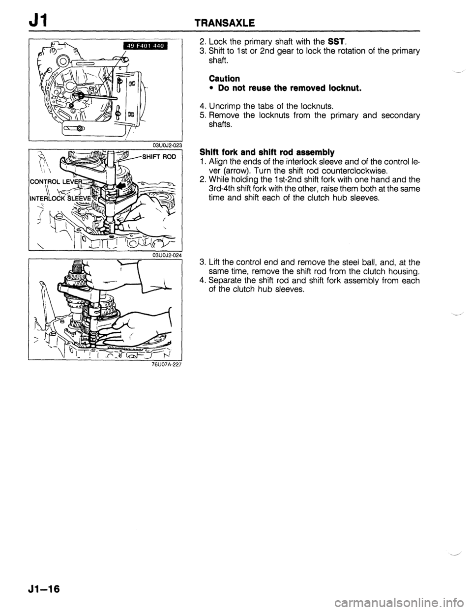
2. Lock the primary shaft with the SST.
3. Shift to 1 st or 2nd gear to lock the rotation of the primary
shaft.
Caution
l Do not reuse the removed locknut.
4. Uncrimp the tabs of the locknuts.
5. Remove the locknuts from the primary and secondary
shafts.
Shift fork and shift rod assembly
1. Align the ends of the interlock sleeve and of the control le-
ver (arrow). Turn the shift rod counterclockwise.
2. While holding the 1 st-2nd shift fork with one hand and the
3rd-4th shift fork with the other, raise them both at the same
time and shift each of the clutch hub sleeves.
3. Lift the control end and remove the steel ball, and, at the
same time, remove the shift rod from the clutch housing.
4. Separate the shift rod and shift fork assembly from each
of the clutch hub sleeves.
51-16
Page 507 of 1164

TRANSAXLE Jl
Clutch Housing and Transaxle Case Components
Caution
l Do not remove oil seals unless necessary.
1. Disassemble in the order shown in the figure, referring to Disassembly Note.
-
.ACE
23UOJl-O(
1. Speedometer driven gear 17. Boot 28. Adjust shim
assembly 18. Oil seal (Change rod) 29. Adjust shim
2. Oil seal (Differential) Disassembly Note 30. Bearing outer race
Disassembly Note ,.,,,..,............. page Jl-18 (Differential)
..................... page Jl-19 19. Bushing Disassembly Note
Replacement (On-vehicle) 20. Oil seal (Primary shaft) ..................... page Jl-19
.....................
page Jl-20 Disassembly Note 31. Adjust shim (Differential)
3. Pivot ..................... page Jl-19 Disassembly Note
4. Bleeder 21. Bearing outer race ..................... page Jl-19
5. Bleeder cover Disassembly Note 32. Transaxle case
6. Gasket ..................... page Jl-18 33. Roll pin
7. Roll pin 22. Funnel 34. O-ring
8. Blind plug Disassembly Note 35. Driven gear
Disassembly Note ..................... page Jl-18 36. Packing
..................... page Jl-18 23. Bearing outer race 37. Oil seal
9. Reverse lever shaft (Differential) (Speedometer gear cace)
Disassembly Note Disassembly Note Disassembly Note
..................... page Jl-18 ..................... page Jl-19 ..................... page Jl-19
10. Lever set spring 24. Clutch housing 38. Gear case
11. Reverse lever 25. Oil passage 39. Joint
Inspection ....... page Jl-27 26. Oil seal (Differential) 40. Change rod
12. Guide plate assembly Disassembly Note
13. Roll pin ..................... page Jl-19
14. Selector Replacement (On-vehicle)
15. Change arm ..................... page Ji-20
16. Change rod assembly 27, Bearing outer race
Jl-17
Page 508 of 1164

Jl TRANSAXLE
03UOJl-025
Disassembly note
Blind plug
1. Remove the roll pin with pliers.
03UOJi-027
03UOJ 1.029
Jl-18
Reverse lever shaft
1. Protect the reverse lever shaft with a rag and remove the
shaft with pliers.
Oil seal (Change rod)
1 .Remove the oil seal with a screwdriver.
Funnel and bearing outer race (Secondary shaft)
Note
l Remove the bearing outer race with a screwdriver
if necessary.
1) Insert a screwdriver between the clutch housing
and bearing outer race.
2)Pt-y the bearing outer race free.
03UOJl-028
1. Remove the bearing outer race by lifting out the funnel and
race together.
Page 509 of 1164

TRANSAXLE
L I
03UOJl-030
03UOJl-03 81
-”
/
23UOJl-004
03UOJ l-03
03UOJl.0:
Oil seal (Primary shaft)
Caution
l Do not damage the clutch housing.
1. Remove the oil seal with a screwdriver.
Oil seal (Differential)
1. Remove the oil seal with a screwdriver.
Bearing outer race (Differential)
1. Remove the bearing outer race with the SST.
Bearing outer race and adjust shim (Differential)
1. Install the SST to the bearing outer race.
2. Remove the bearing outer race and adjust shim.
Oil seal (Speedometer gear case)
1. Remove the oil seal as shown in the figure.
Jl-19
Page 510 of 1164

Jl TRANSAXLE
r
03UOJ2-026
03UOJl-03:
Oil seal
Replacement (On-vehicle)
Jack up the vehicle and support it with safety stands. Drain
the transaxle oil. Next, use the following procedure to replace
the driveshaft oil seal:
1. Remove the front wheel.
2. Remove the splash shield.
3. Separate the front stabilizer from the lower arm.
Caution
l Do not damage the dust boots.
4. Remove the clinch bolt and pull the lower arm downward.
Separate the knuckle from the lower arm ball joint.
5. Loosen the nut and disconnect the tie-rod end with the SST.
Caution
l Do not subject the tripod joint to shock when remov-
ing the driveshaft.
6. Disconnect the driveshaft from the transaxle by prying with
a bar inserted between the outer ring and the transaxle.
7. Suspend the driveshaft with a rope.
03UOJl-036
8. Remove the oil seal with a screwdriver.
03UOJ2-03’
03UOJi-03;
51-20
Note
l Tap in until the oil seal installer contacts the case.
l Coat the oil seal lip with transaxle oil.
9. Tap the new oil seal into the transaxle case with the SST.