MAZDA PROTEGE 1992 Workshop Manual
Manufacturer: MAZDA, Model Year: 1992, Model line: PROTEGE, Model: MAZDA PROTEGE 1992Pages: 1164, PDF Size: 81.9 MB
Page 481 of 1164

CLUTCH MASTER CYLINDER H
/I f-------i- OWOHX-01
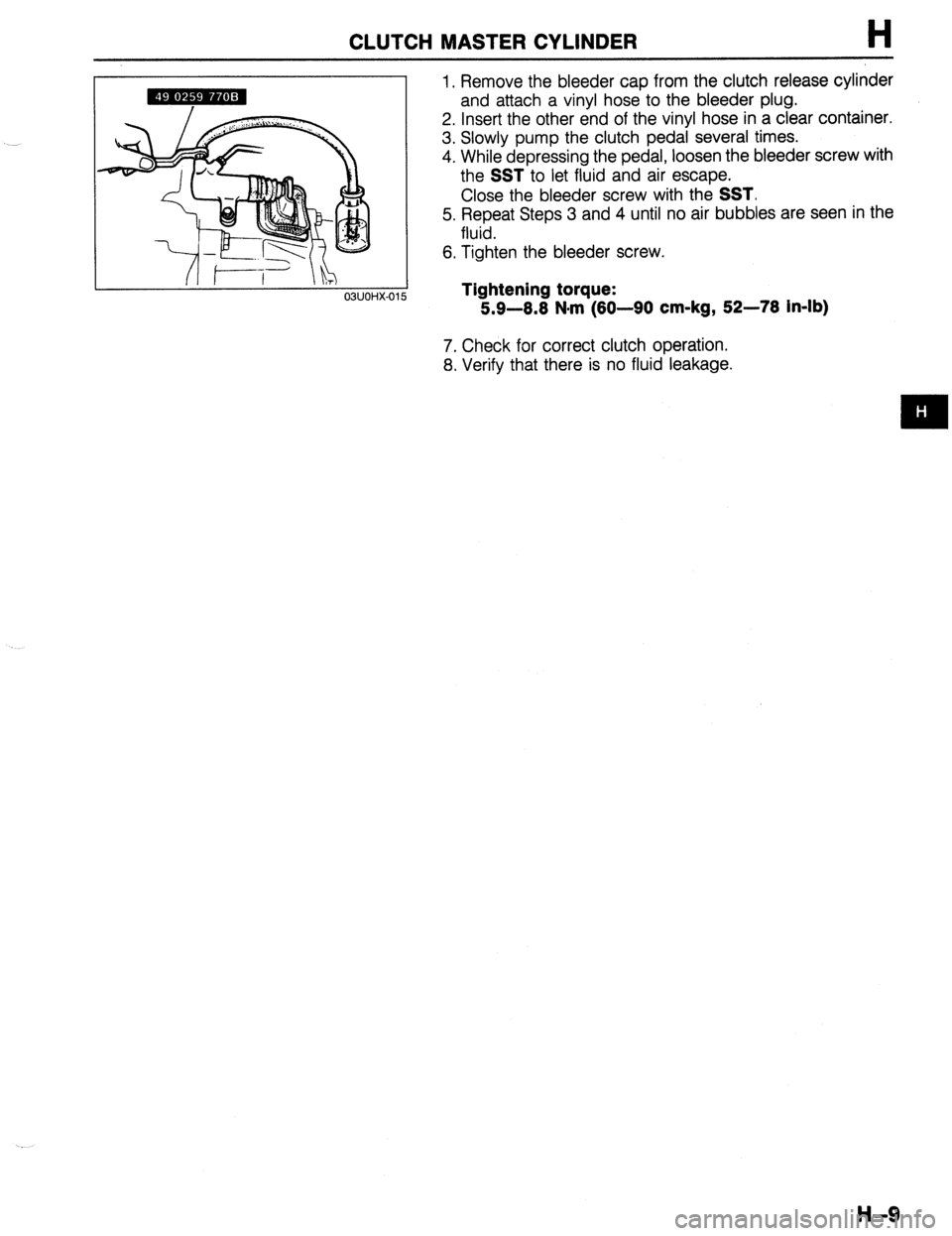
1. Remove the bleeder cap from the clutch release cylinder
and attach a vinyl hose to the bleeder plug.
2. Insert the other end of the vinyl hose in a clear container.
3. Slowly pump the clutch pedal several times.
4. While depressing the pedal, loosen the bleeder screw with
the
SST to let fluid and air escape.
Close the bleeder screw with the
SST.
5. Repeat Steps 3 and 4 until no air bubbles are seen in the
fluid.
6. Tighten the bleeder screw.
Tightening torque:
5.9-8.8 N#rn (80-90 cm-kg, 52-78 in-lb)
7. Check for correct clutch operation.
8. Verify that there is no fluid leakage.
H-9
Page 482 of 1164

H CLUTCH MASTER CYLINDER
OVERHAUL
Caution
l Clean the disassembled parts in solvent and blow through all ports and passages wlth com-
pressed air. .-J
1. Disassemble in the order shown in the figure, referring to Disassembly Note.
2. Inspect all parts and repair or replace as necessary.
3. Assemble in the reverse order of disassembly, referring to
Assembly Note.
I
1. Clip 7. Spacer
2. Hose 8. Primary cup
3. Joint Inspect for wear and cracks
4. Bushing 9. Return spring
5. Snap ring 10. Master cylinder body
Disassembly Note ..,.,..,.........,,,.,......... below Inspect cylinder bore for scoring and
Assembly Note . . . . . . . . . . . . . . . . . . . . . . . . . . . page H-l 1 corrosion
6. Piston and secondary cup assembly
Disassembly Note ,..................... page H-l 1
Assembly Note .,.,.......,...,......,.,,, page H-l 1
Inspect for wear, scoring and cracks
H-10
03UOHX-01
Disassembly Note
Snap ring
Caution
l Do not damage the push rod contact surface of the
piston.
1. Press the piston down and remove the snap ring with snap
ring pliers. -
Page 483 of 1164

CLUTCH MASTER CYLINDER H
SMUOHX-Ol!
03UOHX-02(
03UOHX-02
Piston and secondary cup assembly
Caution
l Hold a rag over the master cylinder to prevent the
piston and secondary cup assembly from jumping
out.
1. Remove the piston and secondary cup assembly, spacer,
and primary cup by applying compressed air through the
clutch pipe installation hole.
Assembly Note
Caution
l Before assembly, make sure all parts are completely
clean.
l Do not mix different brands of clutch fluid.
l Do not reuse the clutch fluid that was drained.
l Apply the specified clutch fluid to the piston and
secondary cup assembly, spacer, primary cup, and
cylinder bore before assembly.
l Replace parts with new ones whenever specified to
do so.
03UOHX-019
Piston and secondary cup assembly
1. Install the spring, primary cup, spacer, and piston and
secondary cup assembly, noting the proper direction of the
parts.
Snap ring
Caution
l Do not damage the push rod contact surface of the
piston.
1. While pressing the piston, install the snap ring.
H-l 1
Page 484 of 1164

H CLUTCH RELEASE CYLINDER
CLUTCH RELEASE CYLINDER
PREPARATION
SST
49 0259 7708 For
Wrench, flare nut e c$on;;;;;!&
clutch pipe
03UOHX-022
REMOVAL / INSTALLATION
Caution
l Clutch fluid will damage painted surfaces. Be sure to use a container or rags to collect it.
If fluid does get on a painted surface, wipe it off immediately with a rag.
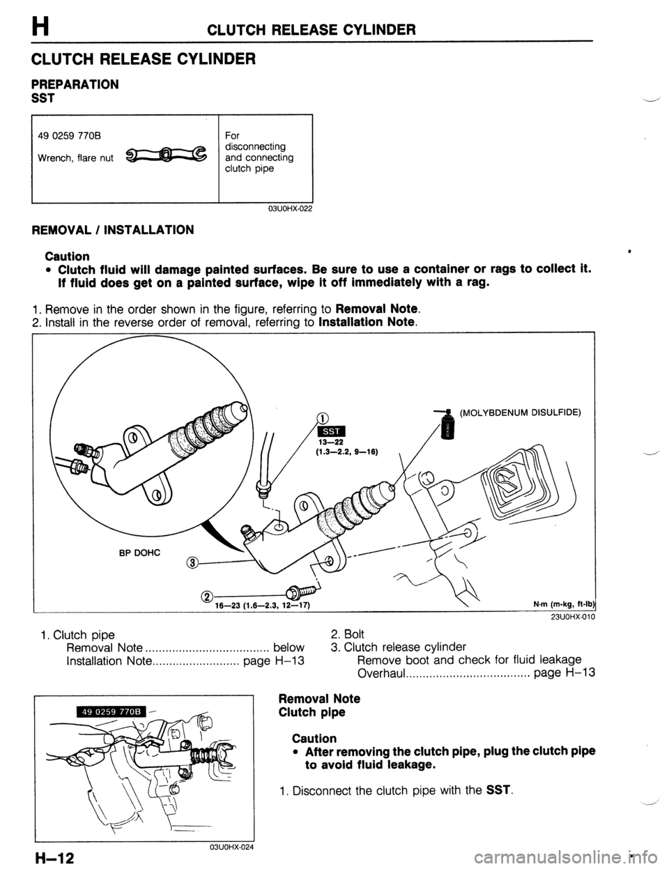
1. Remove in the order shown in the figure, referring to Removal Note.
2. Install in the reverse order of removal, referring to Installation Note.
(MOLYBDENUM DISULFIDE)
(1.3-2.2, S-16)
16-23 (1.6-2.3, 12-17) N.m (m-kg, ft-lb
23UOi-K011
1, Clutch pipe 2. Bolt
Removal Note . . . . . . . . . . . . . . . . . . . . . . . ,........... . . below 3. Clutch release cylinder
installation Note . . . . . . . . . . . . . . . . . . . . . . . . . . page
H-13 Remove boot and check for fluid leakage
Overhaul . . . . . . . . . . . . . . . . . . . . . . . . . . . . . . . . ...*. page H-13
Removal Note
Clutch pipe
03UOHX-024
Caution
l After removing the clutch pipe, plug the clutch pipe
to avoid fluid leakage.
1. Disconnect the clutch pipe with the SST.
H-12 .
Page 485 of 1164

CLUTCH RELEASE CYLINDER
Installation Note
Clutch pipe
H
1. Tighten the clutch pipe with the SST.
Tightening torque:
13-22 N-m (1.3-2.2 m-kg, 9-16 ft-lb)
Air Bleeding
1. After installation, bleed the clutch system.
(Refer to page below.)
23UOHX-011
OVERHAUL
Caution
l Clean the disassembled parts in solvent and blow through all ports and passages with com-
pressed air.
l Before assembly, make sure all parts are completely clean.
l Apply the specified clutch fluid to the piston and cup assembly and cylinder bore before as-
sembly.
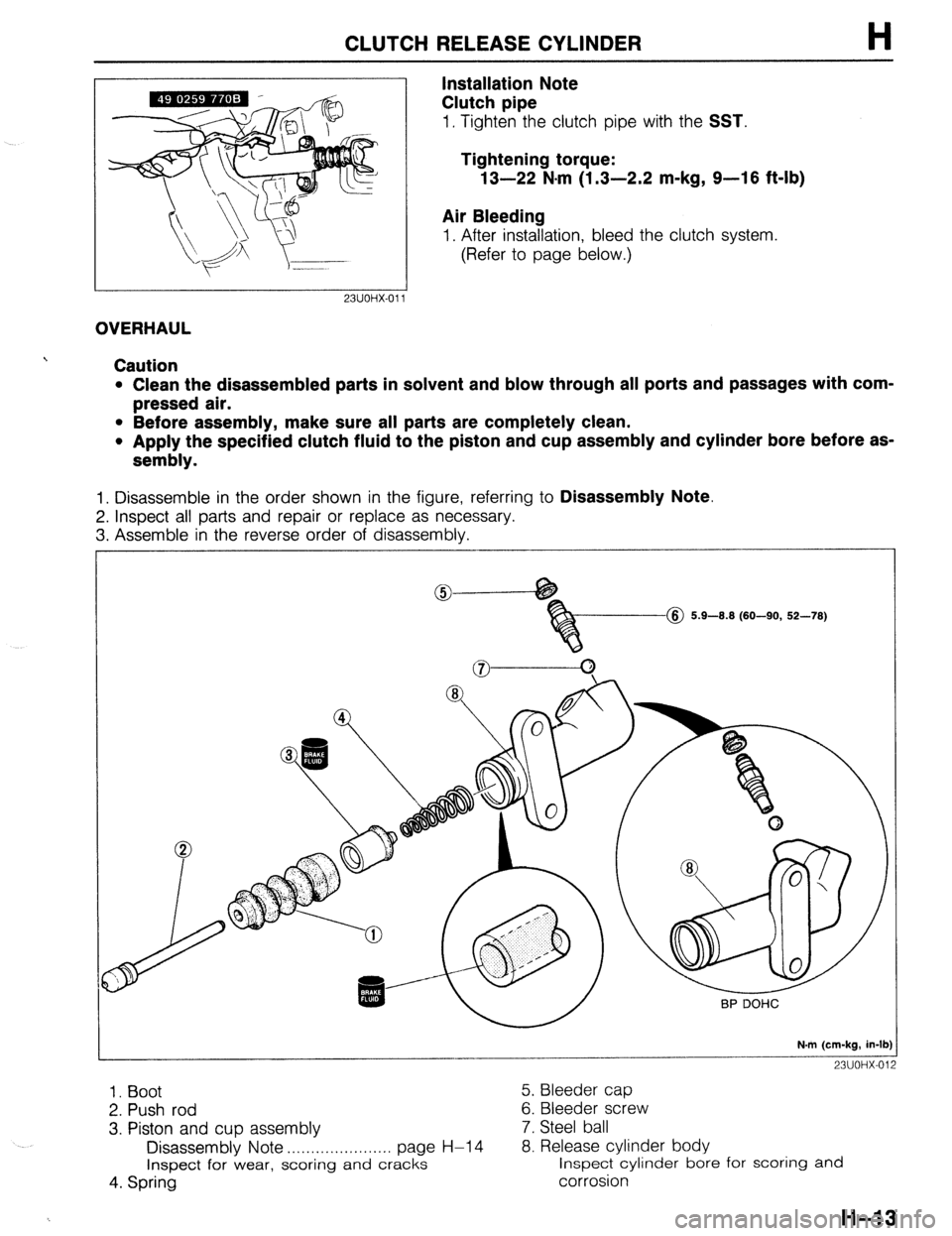
1. Disassemble in the order shown in the figure, referring to Disassembly Note.
2. Inspect all parts and repair or replace as necessary.
3. Assemble in the reverse order of disassembly.
@ 5.9-8.8 (60-90, 52-78)
N.m (cm-kg, in-lb)
23UOHX-012
1. Boot 5. Bleeder cap
2. Push rod 6. Bleeder screw
3. Piston and cup assembly 7. Steel ball
Disassembly Note . . . . . . . . . . . . . . . . . . . . . . page H-l 4 8. Release cylinder body
Inspect for wear, scoring
and cracks inspect cylinder bore for scoring and
4. Spring corrosion
H-13
Page 486 of 1164

H CLUTCH RELEASE CYLINDER, CLUTCH UNIT
Disassembly Note
Piston and cup assembly
Caution
l Hold a rag over the release cylinder to prevent the
piston and cup assembly from suddenly popping
out.
1. Remove the piston and cup assembly by applying com-
pressed air through the clutch pipe installation hole.
I
I
13UOHX-017
CLUTCH UNIT
PREPARATION
SST
49 EOll IA0
Brake set,
ring gear
49 EOll 104
Collor
(Part of
49 EOl 1 1 AO)
49 SE01 310A
Clutch disc
centering tool
49 1285 073
Chuck
IPart of
b9 1285 071) For
prevention of
engine rotation 49 EOll 103
Shaft
(Part of
49 EOl 1 1 AO)
For 49
EOI 1 105 prevention of
engine rotation Stopper 453
(Part of
49 EOl 1 IA0
4
For
installation of
clutch disc 49 1285 071
Puller, bearing
For
removal of pilot
bearing For
prevention of
engine rotation
For
prevention of
engine rotation
23UOHX-013
For
removal of pilot
H-14
Page 487 of 1164

CLUTCH UNIT
REMOVAL / INSTALLATION
Note
l Remove the clutch release cylinder with the clutch pipe connected.
l Do not remove the pilot bearing if not necessary.
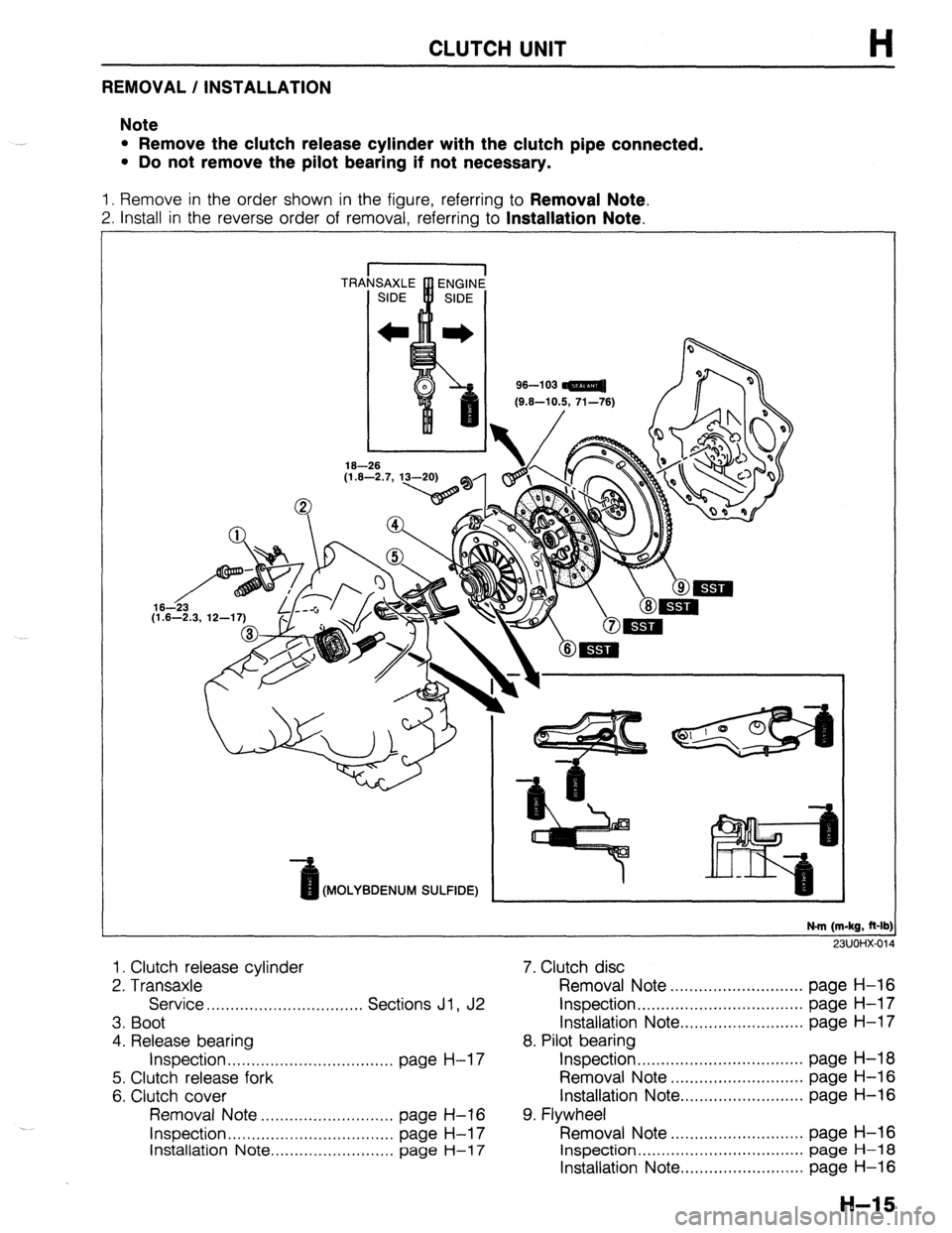
1. Remove in the order shown in the figure, referring to Removal Note.
2. Install in the reverse order of removal, referring to Installation Note.
96-l 03
Kt.6-10.5. 71-761
(MOLYBDENUM SULFIDE)
N-m (m-kg, R-lb:
911 Im-4Y.fi,r
1. Clutch release cylinder
2. Transaxle
Service . . . . . . . . . . . . . . . . . . . . . . . . . ,....... Sections Jl , J2
3. Boot
4. Release bearing
Inspection . . . . . . . . . . . . . . . . . . . . . . . . . . . . . . . . . . . page H-l 7
5. Clutch release fork
6. Clutch cover
Removal Note ..,...........,,,.........,, page H-16
Inspection . . . . . . . . . . . . . . . . . . . . . . . . . . . . . . . . . . . page H-l 7
Installation Note .,......................., page
H-l 7
7. Clutch disc
Removal Note ............................ page H-16
Inspection.. ................................. page H-l 7
Installation Note .......................... page H-l 7
8. Pilot bearing
Inspection ................................... page H-18
Removal Note ............................ page H-16
Installation Note.. ........................ page H-16
9. Flywheel
Removal Note ............................ page H-16
Inspection ................................... page H-18
Installation Note .......................... page H-16
H-15
Page 488 of 1164

H CLUTCH UNIT
/ 6fs 23UOHX-015
Removal Note
Clutch cover and disc
1. Install the SST or equivalent.
2. Loosen each bolt one turn at a time in a crisscross pattern
until spring tension is released. Then remove the clutch COV-
er and disc.
‘6
I
23UOHX-016
23UOHX-01
Pilot bearing
1. Remove the pilot bearing with the SST if necessary.
Flywheel
Note
l After removing the flywheel, inspect for oil leakage
past the crankshaft rear oil seal.
If necessary, replace the oil seal.
(Refer to Section B.) -J
1. Hold the flywheel with the SST or equivalent.
2. Remove the flywheel.
Installation Note
Flywheel
1. Wipe the bolts clean and apply sealant to the bolt threads.
2. Install the flywheel and the
SST or equivalent.
3. Tighten the bolts in the pattern shown.
Tightening torque:
96-103 N,m (9.6-10.5 m-kg, 71-76 ft-lb)
Pilot bearing
Note
l Install the pilot bearing flush with the flywheel.
1. Install the new bearing with a suitable pipe.
Bearing outer diameter: 35mm (1.376 in) .-’
Page 489 of 1164

CLUTCH UNIT, RELEASE BEARING, CLUTCH COVER, CLUTCH DISC H
L
13UOHX-01;
03UOHX-03 8
23UOHX-018
5
03UOHX-032
03UOHX-03
Clutch disc
1. Clean the clutch disc splines and main drive gear splines;
then apply organic molybdenum sulfide grease.
2. Hold the clutch disc in position with the
SST.
Clutch cover
1. Install the SST or equivalent.
2. Align the dowel holes with the flywheel dowels.
3. Tighten the bolts evenly and gradually in the pattern shown.
Tightening torque:
18-26 Nom (1.8-2.7 m-kg, 13-20 ft-lb)
RELEASE BEARING
INSPECTION
Note
l The clutch release bearing Is a sealed bearlng and
must not be washed in solvent.
1. Turn the bearing while applying force in the axial direction.
If the bearing sticks or has excessive resistance, replace it.
CLUTCH COVER
INSPECTION
Note
l Minor scoring or burning should be removed with
emery paper.
1. Inspect the contact surface of the clutch disc for scoring,
cracks, and burning. Repair or replace as necessary.
2. Inspect the contact surface of the clutch release bearing
for wear and cracks.
If there is wear or cracks, replace the clutch cover.
CLUTCH DISC
INSPECTION
Note
l Use sandpaper if the trouble is minor.
1. Inspect the lining surface for burning and oil contamination.
Replace the clutch disc if it is badly burned or oil soaked.
2. Inspect for loose facing rivets and rubbers.
Replace the clutch disc if either is loose.
H-17
Page 490 of 1164

CLUTCH DISC, PILOT BEARING, FLYWHEEL
9
13UOHX-020
03UOHX-03
03UOHX-0:
3. Measure the thickness of the lining at a rivet head on both
sides with vernier calipers.
Replace the clutch disc if its thickness is less than minimum.
Thickness: 0.3mm (0.012 in) min.
4. Measure the clutch disc runout with a dial indicator.
Replace the clutch disc if runout is excessive.
Runout: 0.7mm (0.027 in) max.
PILOT BEARING
INSPECTION
1. Turn the bearing while applying force in the axial direction.
If the bearing sticks or has excessive resistance, replace it.
---
FLYWHEEL
INSPECTION
Note
l Minor scoring or burning should be removed with
emery paper.
1. Inspect the contact surface of the clutch disc for scoring,
cracks, and burning; repair or replace as necessary.
2. Inspect the ring gear teeth for wear and damage. If neces-
sary, replace the ring gear.
3. Measure the flywheel runout with a dial indicator. Replace
the flywheel if runout is excessive.
Runout: 0.2mm (0.008 in) max.