MAZDA PROTEGE 1992 Repair Manual
PROTEGE 1992
MAZDA
MAZDA
https://www.carmanualsonline.info/img/28/57077/w960_57077-0.png
MAZDA PROTEGE 1992 Repair Manual
Trending: inflation pressure, fuse box location, tow, remote control, horn, engine schematic, key
Page 61 of 1164
REMOVAL Bl
Step 4 -
ATX
REPLACE
13UOBl-043
1. Speedometer cable 7. Stabilizer
2. Clutch release cylinder
8. Tie rod end
Removal Note below Removal Note . . . . . . . . . . . . . . . . . . . . . . . . . . . page 61-32
,...............,....................
3. Shift control rod (MTX)
4. Extension bar (MTX)
5. Shift control cable (ATX)
6. Front exhaust pipe 9. Engine mount member
Removal Note ,.......................... page Bl-32
10. Driveshaft
Removal Note . . . . . . . . . . . . . . . . . . . . . . . . . . page 81-32
Removal note
13UOBl-04 .4
Clutch release cylinder (MTX)
1. Remove the release cylinder pipe bracket from the transaxle.
2. Position the release cylinder away from the transaxle for eas-
ier removal with the hose still connected.
Caution
l Do not damage the pipe or hose.
81-31
Page 62 of 1164
Bl REMOVAL
I 03UOBi-05 I
14
‘5
03UOBl-056
Bl-32
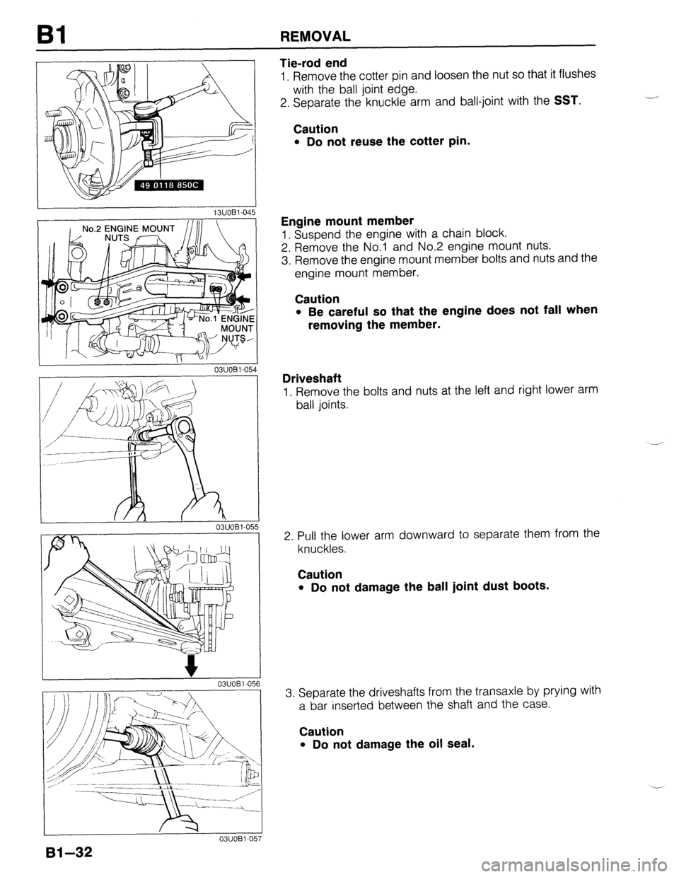
Tie-rod end
1. Remove the cotter pin and loosen the nut so that it flushes
with the ball joint edge.
2. Separate the knuckle arm and ball-joint with the
SST.
Caution
l Do not reuse the cotter pin.
Engine mount member
1. Suspend the engine with a chain block.
2. Remove the No.1 and No.2 engine mount nuts.
3. Remove the engine mount member bolts and nuts and the
engine mount member.
Caution
l Be careful so that the engine does not fall when
removing the member.
Driveshaft
1. Remove the bolts and nuts at the left and right lower arm
ball joints.
2. Pull the lower arm downward to separate them from the
knuckles.
Caution
l Do not damage the ball joint dust boots.
3. Separate the driveshafts from the transaxle by prying with
a bar inserted between the shaft and the case.
Caution
l Do not damage the oil seal.
Page 63 of 1164
REMOVAL Bl
1 Step 5
I
1. Dynamic damper
2. No.3 engine mount rubber
3. No.4 engine mount rubber and bracket 4. Engine and transaxle assembly
Removal note . . . . . . . . . . . . . . . . . . . . . . . . . . . . ..‘....... below
I 03UOBl-059
Removal note
Engine and transaxle assembly
Caution
l Do not damage any components in the engine com-
partment.
1. Lift the engine and transaxle assembly out as a unit.
Bl-33
Page 64 of 1164
REMOVAL
Step 6
Separate the engine and transaxle in the order shown in the figure.
MTX BP SOHC
ATX
BP SOHC
--
03UOB1-060
1. Intake manifold bracket 5. Integrated stiffener (B6 engine)
2. Starter and bracket 6. Torque converter nuts (ATX)
3. Throttle cable (ATX) 7. Transaxle mounting bolts
4. No.2 engine mount rubber and bracket 8. Transaxle
01-34
Page 65 of 1164
ENGINE STAND MOUNTING Bl
ENGINE STAND MOUNTING
PREPARATION
SST
49 0107 680A
49 LO10 1AO)
49 LO10 103
49 LO10 IAO)
49 LO10 105
49 LO10 IAO)
OSUOBX-O(!
m-35
Page 66 of 1164
Bl ENGINE STAND MOUNTING
PROCEDURE
Step 1
1. Remove in the order shown in the figure.
GASKET, REPLACE
I
1. Exhaust manifold insulator
2. Exhaust manifold
3. Water bypass pipe
23UOBl-03
4. A/C compressor bracket (If equipped) and idler
5. Water inlet pipe
6. Exhaust pipe bracket
‘0
Step 2
Caution
l When installing the SST (engine hanger), use the
holes shown in the figure.
Bl-36
Page 67 of 1164
ENGINE STAND MOUNTING Bl
OBUOBX-Ot
OWOBX-0; 36
ENGINE
NlJ/ WkSHER b&i THAP
2Omm (0.79 il
OWOBX-0
I
-I n)
80
OWOBX-089
1. Install the SST (arms) to the holes as shown in the figure,
and loosely tighten the SST (bolts).
2. Assemble the SST (bolts and plate) in the specified po-
sition.
3. Assemble the SST (nuts, hooks, and bolts).
4. Install the SST to the respective arms.
Note
l Adjust the SST (bolts) so that less than 20mm (0.79
in) of thread is exposed.
l Make the SST (plate and arms) parallel by adjust-
ing the SST (bolts and nuts).
5. Tighten the SST (bolts and nuts) to affix the SST firmly.
6. Mount the engine on the SST (engine stand).
81-37
Page 68 of 1164
Bl DISASSEMBLY
DISASSEMBLY
PREPARATION
SST
49 EOl 1 1AO
Ring gear brake
49 EOll 104
49 EOl 1 1 AO)
49 0636 100A
Arm, valve spring removal of valve
49 B012 006
Pivot, valve
49 8012 012
49 8012 014
49 LO11 006
Puller 84 installer
(Part of
49 LO1 1 OAO)
81-38
Page 69 of 1164
DISASSEMBLY Bl
I I
49 LO11 010
Centering tool
(Part of
49 LO1 1 OAO) For
removal I
installation of
piston pins 49 LO11 011
Holder
(Part of
49 LO1 1 OAO) For
removal I
installation of
piston pins
49 HO11 OOlA
Support block
head For
removal /
installation of
piston pins
1. Code all identical parts (such as piston, piston rings, connecting rods, and valve springs) so that they
can be reinstalled in the cylinder from which they were removed.
2. Clean the parts with a steam cleaner. Blow off any remaining water with compressed air.
Note
l During disassembly of any part or system, be sure to study its order of assembly. Also, note
any deformation, wear, or damage.
05UOBX-091
81-39
Page 70 of 1164
Bl DISASSEMBLY
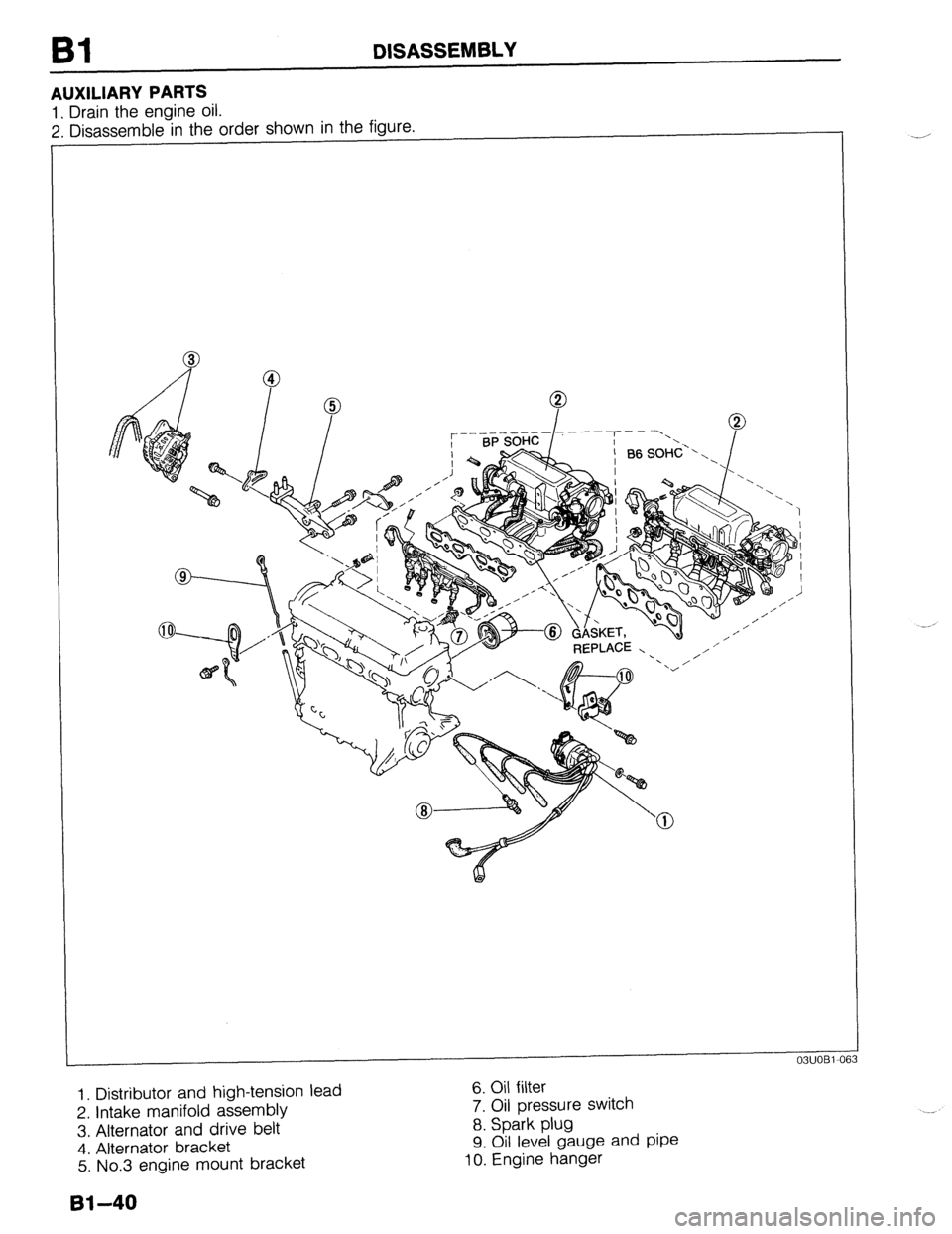
AUXILIARY PARTS
1. Drain the engine oil.
2. Disassemble in the order shown in the figure.
- REPLACE - ’ ,/ I’
1. Distributor and high-tension lead
2. Intake manifold assembly
3, Alternator and drive belt
4. Alternator bracket
5. No.3 engine mount bracket 6. Oil filter
7. Oil pressure switch
8. Spark plug
9. Oil level gauge and pipe 10. Engine hanger
61-40
Trending: check engine, charging, bolt pattern, reset, ignition, remote start, transmission oil


