MAZDA PROTEGE 1992 Manual Online
Manufacturer: MAZDA, Model Year: 1992, Model line: PROTEGE, Model: MAZDA PROTEGE 1992Pages: 1164, PDF Size: 81.9 MB
Page 81 of 1164
DISASSEMBLY Bl
23UOBl-03
05UOBX-1’ 9
23UOBl-040
03UOBl-08 5
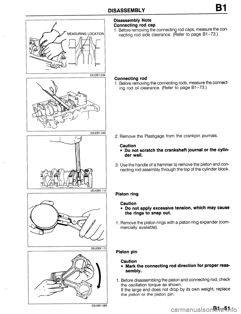
Disassembly Note
Connecting rod cap
1. Before removing the connecting rod caps, measure the con-
necting rod side clearance. (Refer to page Bl-73.)
Connecting rod
1. Before removing the connecting rods, measure the connect-
ing rod oil clearance. (Refer to page Bl-73.)
2. Remove the Plastigage from the crankpin journals.
Caution
l Do not scratch the crankshaft journal or the cylin-
der wall.
3. Use the handle of a hammer to remove the piston and con-
necting rod assembly through the top of the cylinder block.
Piston ring
Caution
l Do not apply excessive tension, which may cause
the rings to snap out.
1. Remove the piston rings with a piston ring expander (com-
mercially available).
Piston pin
Caution
l Mark the connecting rod direction for proper reas-
sembly.
1. Before disassembling the piston and connecting rod, check
the oscillation torque as shown.
If the large end does not drop by its own weight, replace
the piston or the piston pin.
81-51
Page 82 of 1164
Bl DISASSEMBLY
No.1
1
I
,
- 1 9MUOB2-098
NO.2
9MUOB2-101
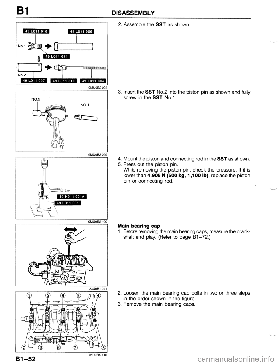
2. Assemble the SST as shown
3. Insert the
SST No.2 into the piston pin as shown and fully
screw in the
SST No.1.
4. Mount the piston and connecting rod in the
SST as shown.
5. Press out the piston pin.
While removing the piston pin, check the pressure. If it is
lower than 4.905 N (500
kg, 1,100 lb), replace the piston
pin or connecting rod.
.--.
Main bearing cap
1. Before removing the main bearing caps, measure the crank-
shaft end play. (Refer to page Bl-72.)
2. Loosen the main bearing cap bolts in two or three steps
in the order shown in the figure.
3. Remove the main bearing caps.
05UOBX.116
Bl-52
Page 83 of 1164
DISASSEMBLY
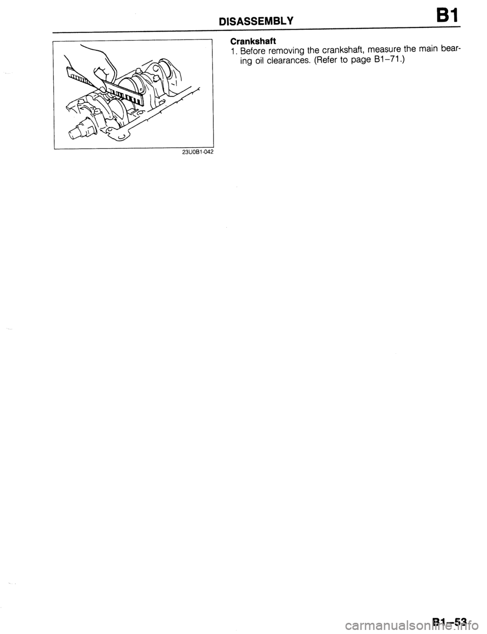
Crankshaft
1. Before removing the crankshaft, measure the main bear-
ing oil clearances. (Refer to page Bl-71.)
2311081-042
Bl-53
Page 84 of 1164
Bl INSPECTION / REPAIR
INSPECTION / REPAIR
PREPARATION
SST
49 LO12 OAO)
Remover and
03UOBi-08
1. Clean all parts, being sure to remove all gasket fragments, dirt, oil or grease, carbon, moisture residue,
and other foreign materials.
2. Inspection and repairs must be performed in the order specified. .__a
Caution
l Do not damage the joints or friction surfaces of aluminum alloy components (such as the cyl-
inder head or pistons).
81-54
03UOBl-090 05UOBX-119
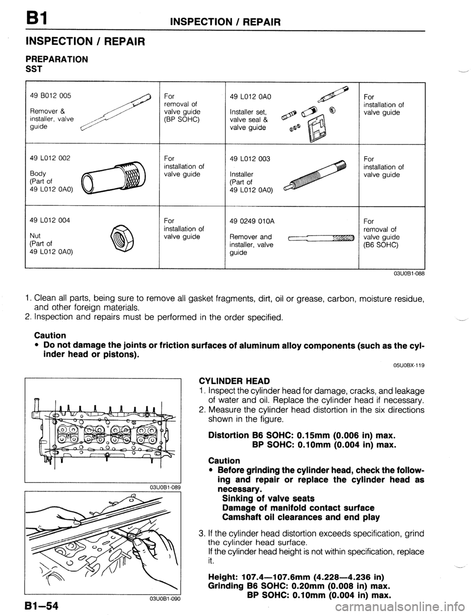
CYLINDER HEAD
1. Inspect the cylinder head for damage, cracks, and leakage
of water and oil. Replace the cylinder head if necessary.
2. Measure the cylinder head distortion in the six directions
shown in the figure.
Distortion B6 SOHC: 0.15mm (0.006 in) max.
BP SOHC: O.lOmm (0.004 in) max.
Caution
l Before grinding the cylinder head, check the follow-
ing and repair or replace the cylinder head as
necessary.
Sinking of valve seats
Damage of manifold contact surface
Camshaft oil clearances and end play
3. If the cylinder head distortion exceeds specification, grind
the cylinder head surface.
If the cylinder head height is not within specification, replace
it.
Height: 107.4-l 07.6mm (4.228-4.236 in)
Grinding B6 SOHC: 0.20mm (0.008 in) max.
BP SOHC: O.lOmm (0.004 in) max.
Page 85 of 1164
INSPECTION / REPAIR Bl
1
I
0311082-007
STEM TIP
MARGIN
THICKNESS
23UOBl-072
2311091.04:
2311091.04.
II- VALVE STEM
VALVE
CLEARANCE
J 05UOBX-125
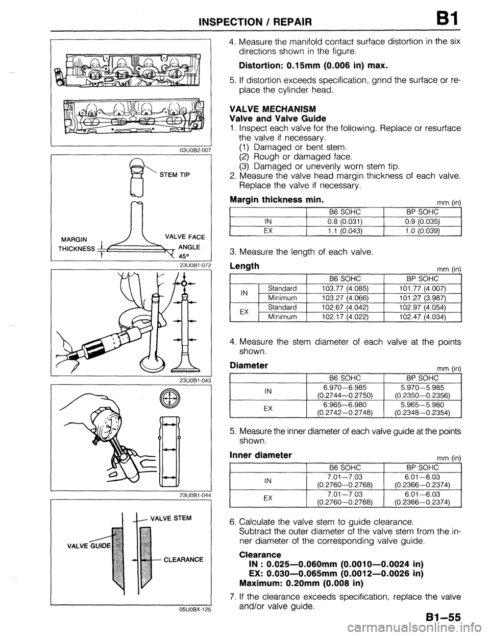
4. Measure the manifold contact surface distortion in the six
directions shown in the figure.
Distortion: 0.15mm (0.006 in) max.
5. If distortion exceeds specification, grind the surface or re-
place the cylinder head.
VALVE MECHANISM
Valve and Valve Guide
1. Inspect each valve for the following. Replace or resurface
the valve if necessary.
(1) Damaged or bent stem.
(2) Rough or damaged face.
(3) Damaged or unevenly worn stem tip.
2. Measure the valve head margin thickness of each valve.
Replace the valve if necessary.
Margin thickness min.
mm (in)
B6 SOHC BP SOHC
IN 0.8 (0.031) 0.9 (0.035)
EX 1.1 (0.043)
1 .o (0.039)
3. Measure the length of each valve.
Length
mm (in)
4. Measure the stem diameter of each valve at the points
shown.
Diameter
IN
EX B6 SOHC
6.970-6.985
(0.2744-0.2750)
6.965-6.980
(0.2742-0.2748) mm (in)
BP SOHC
5.970-5.985
(0.2350-0.2356)
5.965-5.980
(0.2348-0.2354)
5. Measure the inner diameter of each valve guide at the points
shown.
Inner diameter
mm (in)
66 SOHC BP SOHC
IN 7.01-7.03 6.01-6.03
(0.2760-0.2768) (0.2366-0.2374)
EX 7.01-7.03 6.01-6.03
(0.2760-0.2768) (0.2366-0.2374)
6. Calculate the valve stem to guide clearance.
Subtract the outer diameter of the valve stem from the in-
ner diameter of the corresponding valve guide.
Clearance
IN : 0.025-0.060mm (0.0010-0.0024 in)
EX: 0.030-0.065mm (0.0012-0.0026 in)
Maximum: 0.20mm (0.008 in)
7. If the clearance exceeds specification, replace the valve
and/or valve guide.
Bl-55
Page 86 of 1164
Bl INSPECTION / REPAIR
VALVE GUIDE
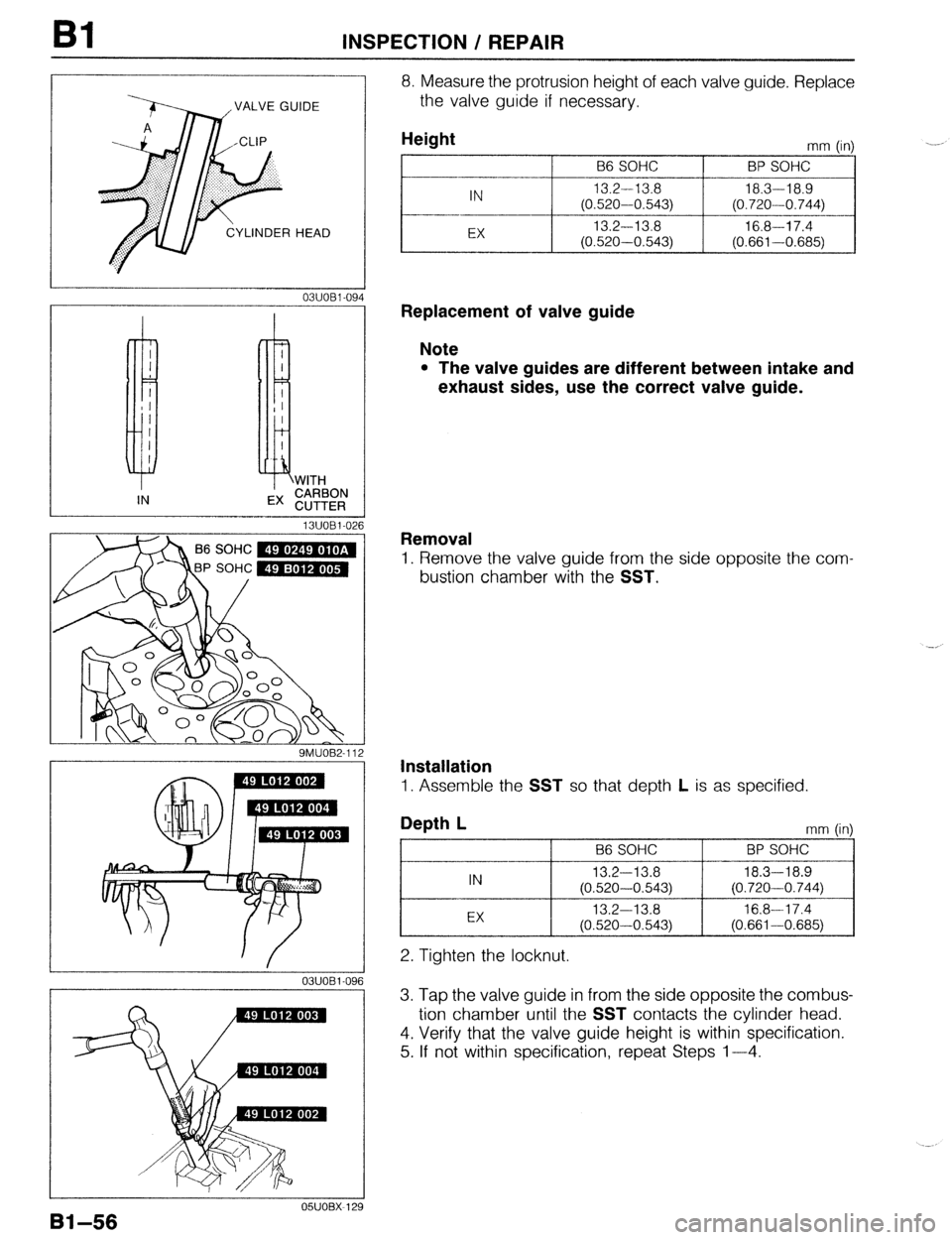
8. Measure the protrusion height of each valve guide. Replace
the valve guide if necessary.
13UOBl-026
P SOHC m
9MUOB2-112
OSUOBX-12’
Bi-56
Height
B6 SOHC mm (in)
BP SOHC
I
IN 13.2-13.8 18.3-i 8.9
(0.520-0.543)
(0.720-0.744)
-.. --
EX 13.2-13.8 16.8-17.4
(0.520-0.543) (0.661-0.685)
Replacement of valve guide
Note
l The valve guides are different between intake and
exhaust sides, use the correct valve guide.
Removal
1. Remove the valve guide from the side opposite the com-
bustion chamber with the SST.
Installation
1. Assemble the SST so that depth L is as specified.
Depth L
mm (in)
I B6 SOHC
I BP SOHC
I
IN 13.2-13.8 18.3-l 8.9
(0.520-0.543) (0.720-0.744)
EX 13.2-13.8 16.8-17.4
(0.520-0.543) (0.661-0.685)
2. Tighten the locknut.
3. Tap the valve guide in from the side opposite the combus-
tion chamber until the SST contacts the cylinder head.
4. Verify that the valve guide height is within specification.
5. If not within specification, repeat Steps l-4.
Page 87 of 1164
INSPECTION / REPAIR Bl
-- 05lJOBX-13
.- __--- 0
-_.--__I__
--
05UOBX.131
B6 SOHC
EX
IN
BP SOHC --~ -____
03uoEI-09
--__.
86 SOHC -
23UOBl-073
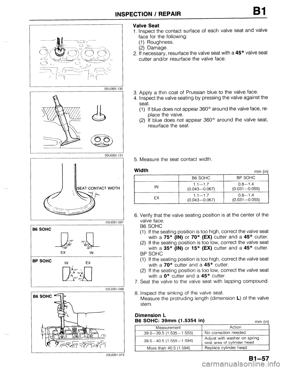
Valve Seat
1, Inspect the contact surface of each valve seat and valve
face for the following:
(1) Roughness.
(2) Damage.
2. If necessary, resurface the valve seat with a 45O valve seat
cutter and/or resurface the valve face.
3. Apply a thin coat of Prussian blue to the valve face.
4. Inspect the valve seating by pressing the valve against the
seat.
(1) If blue does not appear 360° around the valve face, re-
place the valve.
(2) If blue does not appear 360° around the valve seat,
resurface the seat
5. Measure the seat contact width.
Width
mm (in)
96 SOHC BP SOHC
IN l.l--1.7 0.8-l .4
(0.043-0.067) (0.031-0.055)
EX 1.1-1.7 0.8-l .4
(0.043-0.067) (0.031-0.055)
6. Verify that the valve seating position is at the center of the
valve face.
B6 SOHC
(1) If the seating position is too high, correct the valve seat
with a 75O (IN) or 70° (EX) cutter and a 45O cutter.
(2) If the seating position is too low, correct the valve seat
with a 35O (IN) or 15O (EX) cutter and a 45O cutter.
BP SOHC
(1) If the seating position is too high, correct the valve seat
with a 70° cutter and a 45O cutter.
(2) If the seating position is too low, correct the valve seat
with a O” cutter and a 45O cutter.
7. Seat the valve to the valve seat with lapping compound.
8. Inspect the sinking of the valve seat.
Measure the protruding length (dimension L) of the valve
stem.
Dimension L
B6 SOHC: 39mm
(1.5354 in) mm fin
Page 88 of 1164
Bl INSPECTION / REPAIR
r
BP SPHC
I /
._~~ ~_ ’
--
23UOB1-06(
1
I 2-l
_I_
23UOBl-074
lt- OUT-OF-SQUARE
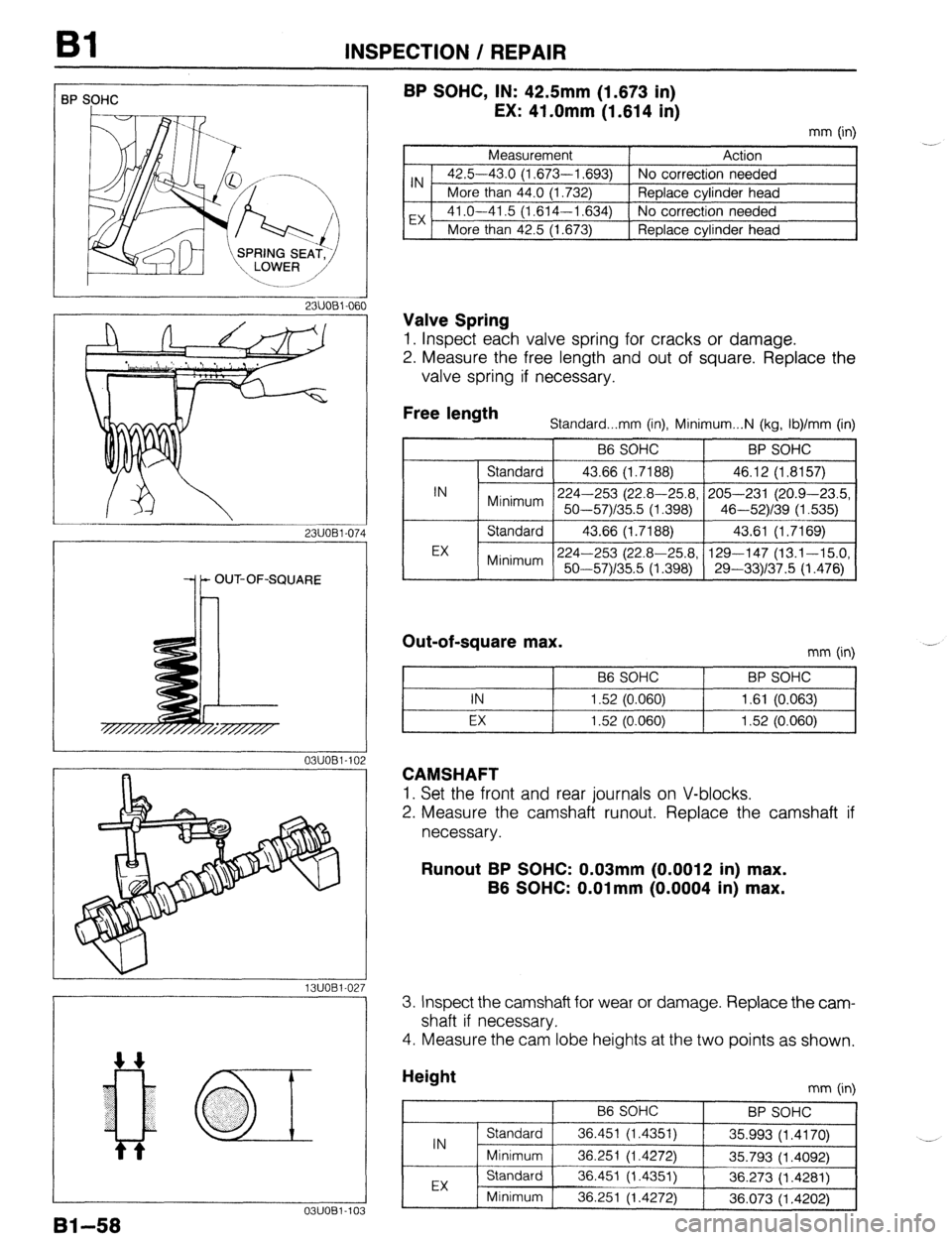
BP SOHC, IN: 42.5mm (1.673 in)
EX: 41 .Omm ‘(1.614 ii)
mm (in)
Measurement Action
IN . 42.5-43.0 (1,673-l ,693) No correction needed
More than 44.0 (1.732) Replace cylinder head
EX 41 .O-41.5 (1,614-l ,634) No correction needed
More than 42.5 (1.673) Replace cylinder head
Valve Spring
1. Inspect each valve spring for cracks or damage.
2. Measure the free length and out of square. Replace the
valve spring if necessary.
Free length
Standard...mm (in), Minimum...N (kg, Ib)/mm (in)
B6 SOHC BP SOHC
I
IN Standard 43.66 (1.7188) 46.12 (1.8157)
224-253 (22.8-25.8, 205-231 (20.9-23.5,
Minimum 50-57)/35.5 (1.398) 46-52)/39 (1.535)
EX Standard 43.66 (1.7188) 43.61 (1.7169)
224-253 (22.8-25.8, 129-147 (13.1-15.0,
Minimum 50-57Y35.5 (1.398) 29-331137.5 (1.476)
Out-of-square max. mm (in)
B6 SOHC BP SOHC I
I I IN 1.52 (0.060) 1.61 (0.063)
t I I
I I EX 1.52 (0.060) 1.52 (0.060)
CAMSHAFT
1. Set the front and rear journals on V-blocks.
2. Measure the camshaft runout. Replace the camshaft if
necessary.
Runout BP SOHC: 0.03mm (0.0012 in) max.
B6 SOHC: O.Olmm (0.0004 in) max.
13UOBl.02; 3. Inspect the camshaft for wear or damage. Replace the cam-
shaft if necessary.
4. Measure the cam lobe heights at the two points as shown.
0311081-103
91-58
mm (in)
Page 89 of 1164
INSPECTION / REPAIR
23UOBl-07
2311081-07
23UOBl.07t
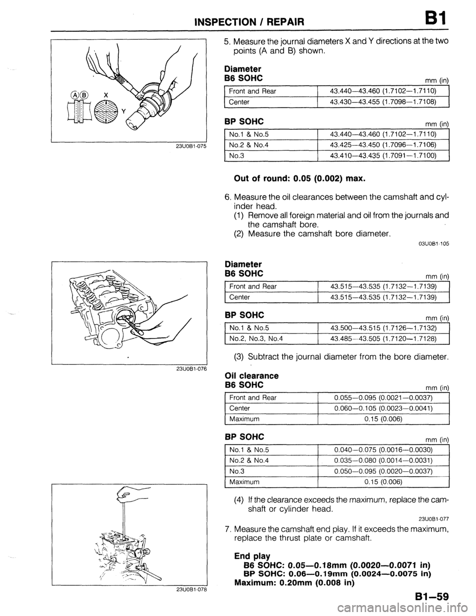
5. Measure the journal diameters X and Y directions at the two
points (A and B) shown.
Diameter
B6 SOHC
Front and Rear
Center mm (in)
43.440-43.460 (1.7102-1.7110)
43.430-43.455 (1.7098--1.7108)
BP SOHC
1 No.1 & No.5 1 43.440-43.460 (1.7102-1.7110) 1
1 No.2 & No.4
1 43.425-43.450 (1.7096-1.7106) 1
1 No.3
I 43.410-43.435 (1.7091-1.7100) I
Out of round: 0.05 (0.002) max.
6. Measure the oil clearances between the camshaft and cyl-
inder head.
(1) Remove all foreign material and oil from the journals and
the camshaft bore.
(2) Measure the camshaft bore diameter.
03UOBV105
Diameter
B6 SOHC
Front and Rear
Center mm (in)
43.515-43.535 (1.7132-1.7139)
43.515-43.535 (1.7132-1.7139)
BP SOHC
1 No.1 & No.5 ] 43.500-43.515 (1.7126-1.7132) 1
1 No.2, No.3, No.4 1 43.485-43.505 (1.7120-1.7128) 1
(3) Subtract the journal diameter from the bore diameter.
Oil clearance
B6 SOHC
mm fin)
Front and Rear 0.055-0.095 (0.0021-0.0037)
Center 0.060-0.105 (0.0023-0.0041)
I
I Maximum
I 0.15 (0.006) I
BP SOHC mm fin
No.1 & No.5
No.2 & No.4
No.3
Maximum 0.040-0.075 (0.0016-0.0030)
0.035-0.080 (0.0014-0.0031)
0.050-0.095 (0.0020-0.0037)
0.15 (0.006)
(4) If the clearance exceeds the maximum, replace the cam-
shaft or cylinder head.
23UOBl-077
7. Measure the camshaft end play. If it exceeds the maximum,
replace the thrust plate or camshaft.
End play
B6 SOHC: 0.05-O. 18mm (0.0020-0.0071 in)
BP SOHC: 0.06-0.19mm (0.0024-0.0075 in)
Maximum: 0.20mm (0.008 in)
Bl-59
Page 90 of 1164
Bl INSPECTION / REPAIR
a3
03UOBl.109
03UOBl-11t
03UOBl-111 i
3
03UOBl-112
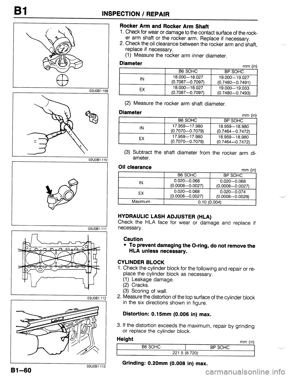
Rocker Arm and Rocker Arm Shaft
1. Check for wear or damage to the contact surface of the rock-
er arm shaft or the rocker arm. Replace if necessary.
2. Check the oil clearance between the rocker arm and shaft,
replace if necessary.
(1) Measure the rocker arm inner diameter.
Diameter mm (in)
B6 SOHC
BP SOHC
IN 18.000-l 8.027
19.000-19.027
(0.7087-0.7097)
(0.7480-0.7491)
EX 18.000-l 8.027
19.000-19.033
(0.7087-0.7097) (0.7480-0.7493)
(2) Measure the rocker arm shaft diameter.
Diameter mm tin1
IN
EX B6 SOHC
BP SOHC ’ ’
17.959-l 7.980
18.959-18.980
(0.7070-0.7079)
(0.7464-0.7472)
17.959-l 7.980
18.959-l 8.980
(0.7070-0.7079)
(0.7464-0.7472)
(3) Subtract the shaft diameter from the rocker arm di-
ameter.
Oil clearance
IN
EX
Maximum mm (in)
B6 SOHC
BP SOHC
0.020-0.068
0.020-0.068
(0.0008-0.0027) (0.0008-0.0027)
0.020-0.068
0.020-0.074
(0.0008-0.0027) (0.0008-0.0029)
0.10 (0.004) -_
HYDRAULIC LASH ADJUSTER (HLA)
Check the HLA face for wear or damage and replace if
necessary.
Caution
l To prevent damaging the O-ring, do not remove the
HLA unless necessary.
CYLINDER BLOCK
1. Check the cylinder block for the following and repair or re-
place the cylinder block as necessary.
(1) Leakage damage.
(2) Cracks.
(3) Scoring of wall.
2. Measure the distortion of the top surface of the cylinder block
in the six directions shown in figure.
Distortion: 0.15mm (0.006 in) max.
3. If the distortion exceeds the maximum, repair by grinding
or replace the cylinder block.
Height
t mm (in)
86 SOHC
BP SOHC _._
221.5 (8.720)
Grinding: 0.20mm (0.006 in) max. U3UU81-113