MITSUBISHI 3000GT 1991 Service Manual
Manufacturer: MITSUBISHI, Model Year: 1991, Model line: 3000GT, Model: MITSUBISHI 3000GT 1991Pages: 1146, PDF Size: 76.68 MB
Page 191 of 1146
FUEL SYSTEM - On-vehicle Inspection of MPI Components13-85 1
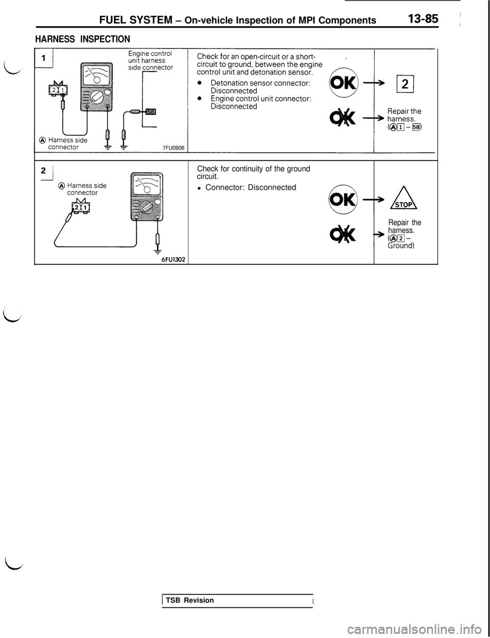
HARNESS INSPECTION
Check for continuity of the ground
circuit.l Connector: Disconnected
Repair the
harness.
76FU1302
1 TSB RevisionI
id
Page 192 of 1146
13-86FUEL SYSTEM - On-vehicle Inspection of MPI Components
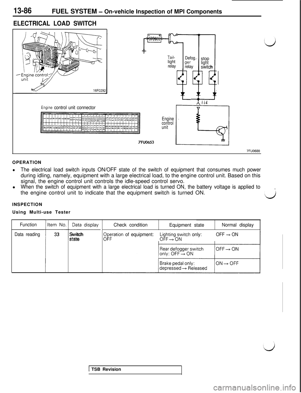
ELECTRICAL LOAD SWITCH16FO29;
Tail-lightrelayDefog.wrelaystoplight
t;1
switch
ti* . .
Engine control unit connector
Engine
control
unit7FUO653
7FUO688OPERATION
lThe electrical load switch inputs ON/OFF state of the switch of equipment that consumes much powerduring idling, namely, equipment with a large electrical load, to the engine control unit. Based on this
signal, the engine control unit controls the idle-speed control servo.
l
When the switch of equipment with a large electrical load is turned ON, the battery voltage is applied tothe engine control unit to indicate that the equipment switch is turned ON.,
LJINSPECTION
Using Multi-use Tester
Function
Data reading
I
tem No. Data display
-I-
33Switchstate
Check condition
Equipment stateNormal display
$;ration of equipment:L$ing;Atch only:OFF + ON-3
1 TSB Revision
Page 193 of 1146
FUEL SYSTEM - On-vehicle InsDection of MPI ComDonents
/
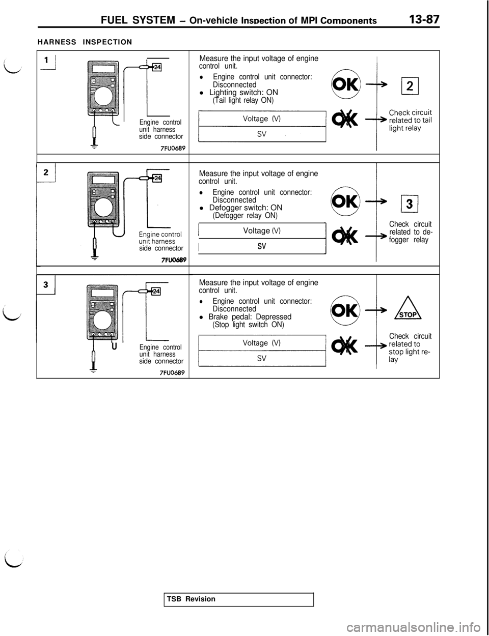
idHARNESS INSPECTION
Engine control
unit harness
side connector7FUO689
side connector7FuO689
PU
Engine control
unit harness
side connectorT7FUO689
Measure the input voltage of engineIcontrol unit.
lEngine control unit connector:
Disconnectedl Lighting switch: ON
(Tail light relay ON)
Measure the input voltage of enginecontrol unit.
lEngine control unit connector:
Disconnectedl Defogger switch: ON
(Defogger relay ON)Voltage
(V)
Isv
cl3
Check circuit
related to de-
fogger relay
Measure the input voltage of enginecontrol unit.
lEngine control unit connector:
Disconnected
l Brake pedal: Depressed(Stop light switch ON)
Check circuitTSB Revision
Page 194 of 1146
13-88FUEL SYSTEM - On-vehicle Inspection of MPI Components
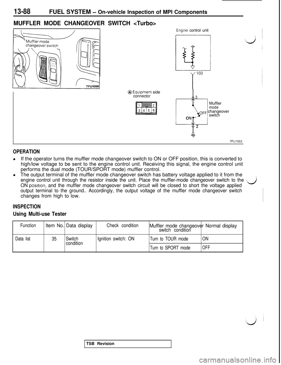
MUFFLER MODE CHANGEOVER SWITCH
Engine control unit
r
@ Equipment sideconnector3
-Muffler
modeOFF changeover
ONswitch
2
r
7FU1053
OPERATIONlIf the operator turns the muffler mode changeover switch to ON or OFF position, this is converted to
high/low voltage to be sent to the engine control unit. Receiving this signal, the engine control unit
performs the dual mode (TOUR/SPORT mode) muffler control.
lThe output terminal of the muffler mode changeover switch has battery voltage applied to it from the
engine control unit through the resistor inside the unit. Place the muffler-mode changeover switch to the ‘LJj
ON posrtton, and the muffler mode changeover switch circuit will be closed to short the voltage applied
output terminal to the ground.. Accordingly, the output voltage of the muffler mode changeover switchchanges from high to low.
INSPECTION
Using Multi-use Tester
FunctionItem No. Data displayCheck conditionMuffler mode changeover Normal displayswitch condition
Data list35Switch
conditionIgnition switch: ONTurn to TOUR mode
Turn to SPORT modeON
OFFTSB Revision
Page 195 of 1146
FUEL SYSTEM - 0n-vehicleInspection of MPI Components13-89 ~
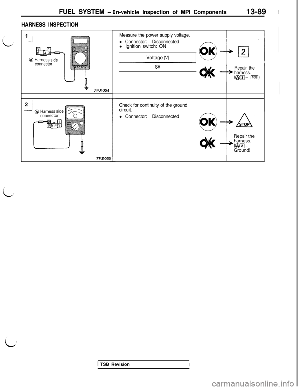
HARNESS INSPECTION
1
connector
*7FU10547FU105:
ii
Measure the power supply voltage.
l Connector: Disconnectedl Ignition switch: ON
Voltage
(V)
sv
i+
Repair the
harness.
@pJ- Ilosi)
Check for continuity of the ground
circuit.
l Connector: Disconnected
1 TSB RevisionI
Page 196 of 1146
13-90FUEL SYSTEM - On-vehicle Inspection of MPI Components
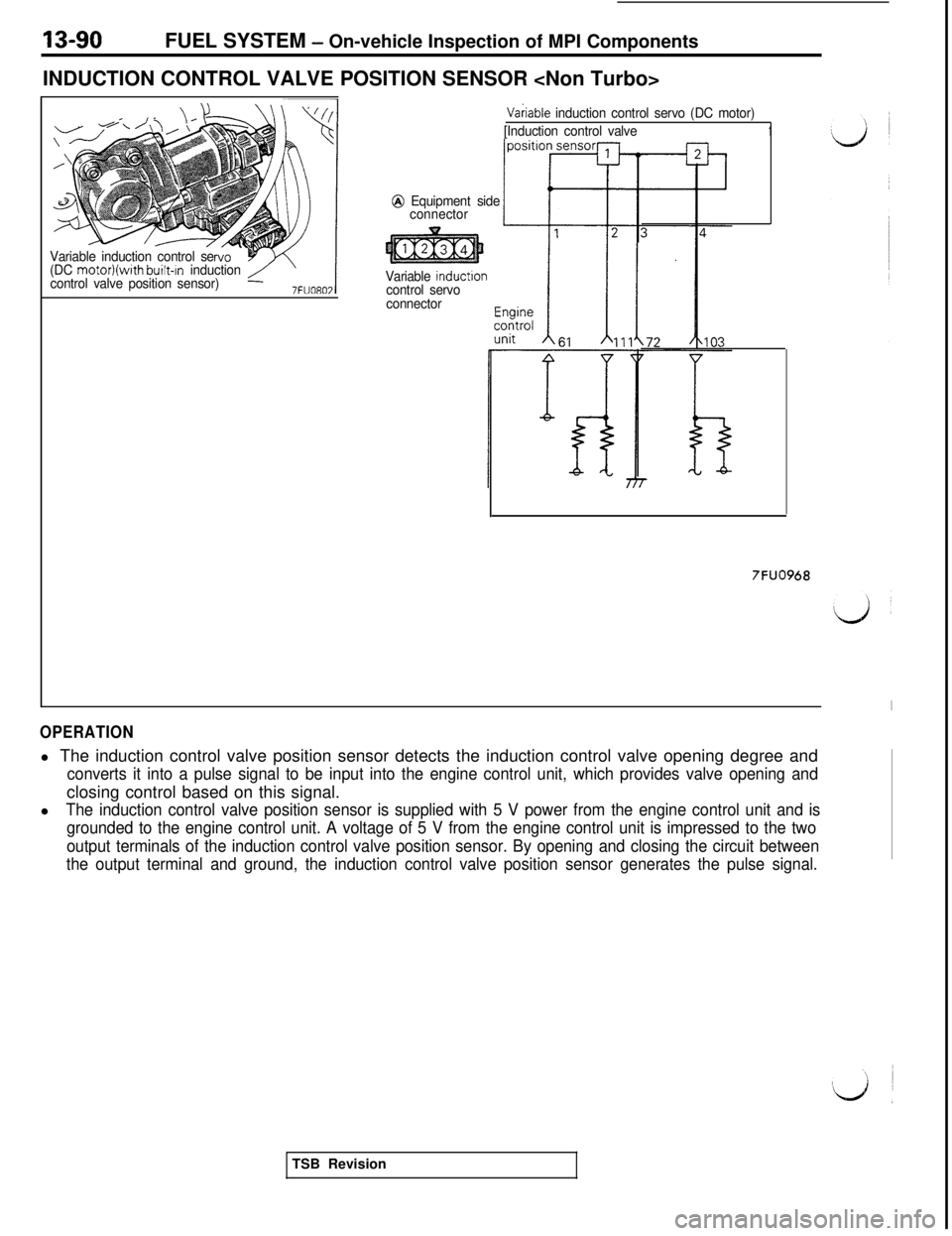
INDUCTION CONTROL VALVE POSITION SENSOR
Variable induction control se
(DC motor)(with built-In induction
control valve position sensor)
Vakiable induction control servo (DC motor)
[Induction control valve
1
@ Equipment side
connector
Variable
inductloncontrol servo
connector
7FUO968
OPERATIONl The induction control valve position sensor detects the induction control valve opening degree and
converts it into a pulse signal to be input into the engine control unit, which provides valve opening andclosing control based on this signal.
l
The induction control valve position sensor is supplied with 5 V power from the engine control unit and is
grounded to the engine control unit. A voltage of 5 V from the engine control unit is impressed to the two
output terminals of the induction control valve position sensor. By opening and closing the circuit between
the output terminal and ground, the induction control valve position sensor generates the pulse signal.TSB Revision
Page 197 of 1146
FUEL SYSTEM - On-vehicle Inspection of MPI Components13-91
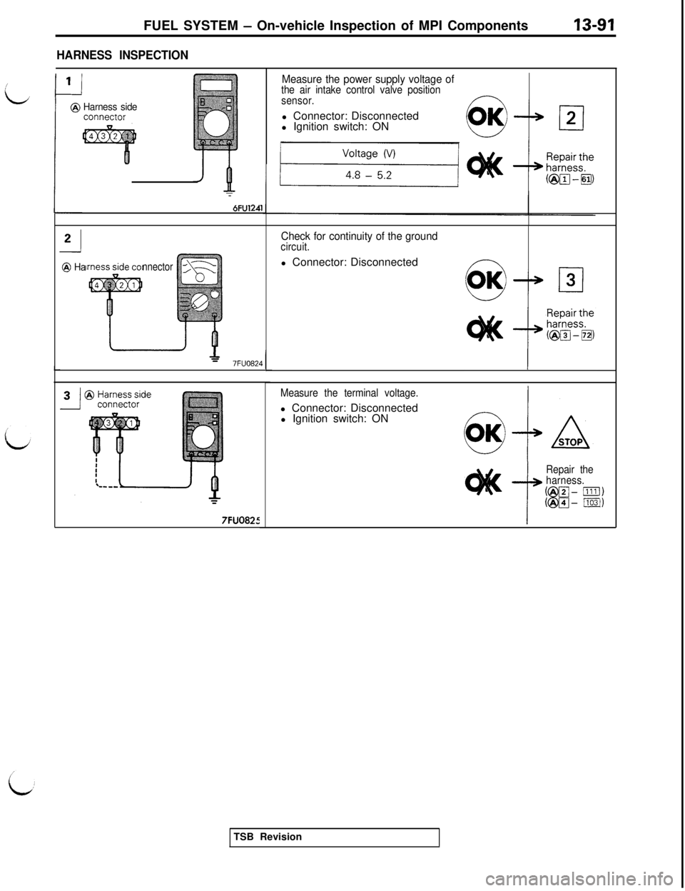
HARNESS INSPECTION
i‘@ Harness side
:
7
6FU1241
Measure the power supply voltage ofthe air intake control valve position
sensor.l Connector: Disconnected
l Ignition switch: ON
@ Hannector
=7FUO824
7FUO825
Check for continuity of the groundcircuit.l Connector: Disconnected
f---Y -
Measure the terminal voltage.l Connector: Disconnected
l Ignition switch: ON
T
Repair the
harness.TSB Revision
Page 198 of 1146
FUEL SYSTEM - On-vehicle Inspection of MPI Components
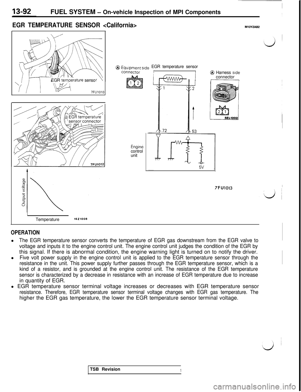
EGR TEMPERATURE SENSOR
EGR tem0erature senso
7FUlOlO
@ Equipment s,de EGR temperature sensor
connectorII@ Harness side
Enginecontrol
unit
I Iconnector
7FU1013I
Temperature1621008
OPERATIONl
The EGR temperature sensor converts the temperature of EGR gas downstream from the EGR valve to
voltage and inputs it to the engine control unit. The engine control unit judges the condition of the EGR bythis signal. If there is abnormal condition, the engine warning light is turned on to notify the driver.
l
Five volt power supply in the engine control unit is applied to the EGR temperature sensor through the
resistance in the unit. This power supply further passes through the EGR temperature sensor, which is a
kind of a resistor, and is grounded at the engine control unit. The resistance of the EGR temperature
sensor is characterized by a decrease in resistance with an increase of EGR temperature due to increasein quantity of EGR.
l EGR temperature sensor terminal voltage increases or decreases with EGR temperature sensor
resistance. Therefore, EGR temperature sensor terminal voltage changes with EGR gas temperature. Thehigher the EGR gas temperature, the lower the EGR temperature sensor terminal voltage.
TSB Revision
1
Page 199 of 1146
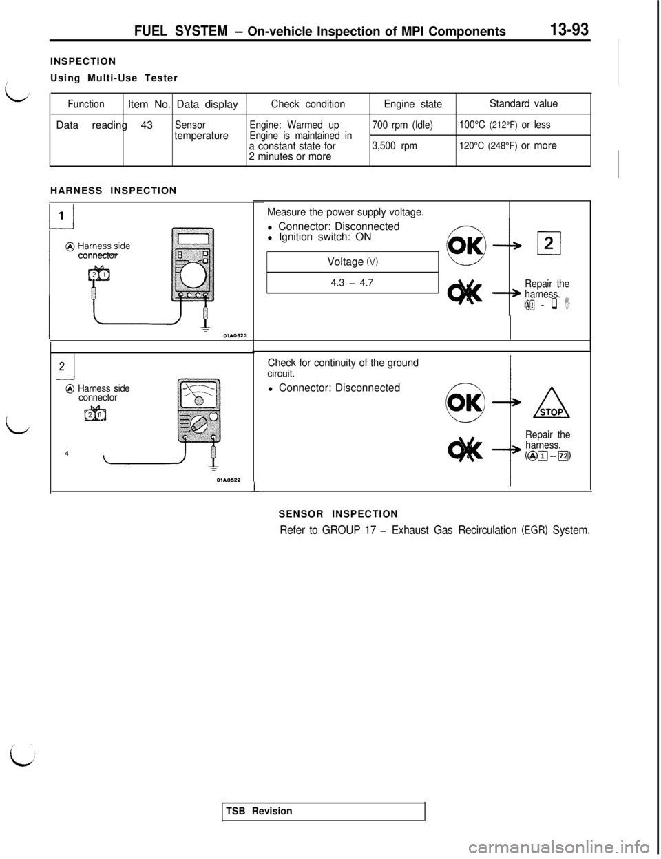
FUEL SYSTEM- On-vehicle Inspection of MPI Components13-93INSPECTION
Using Multi-Use Tester
FunctionItem No. Data displayCheck conditionEngine stateStandard valueData reading 43
SensorEngine: Warmed up700 rpm (Idle)100°C (212°F) or less
temperatureEngine is maintained in-
a constant state for3,500 rpm120°C (248°F) or more
2 minutes or moreHARNESS INSPECTION
connector
2-..-I
@ Harness side
connector
m2 1
4
1
Measure the power supply voltage.l Connector: Disconnected
l Ignition switch: ON
Voltage
(V)4.3
- 4.7Repair the
harness.
(@I@ - q I
Check for continuity of the groundcircuit.
l Connector: Disconnected
I
Repair the
harness.@@J-m,
SENSOR INSPECTION
Refer to GROUP 17 - Exhaust Gas Recirculation (EGR) System.TSB Revision
Page 200 of 1146
FUEL SYSTEM - On-vehicle Inspection of MPI Components
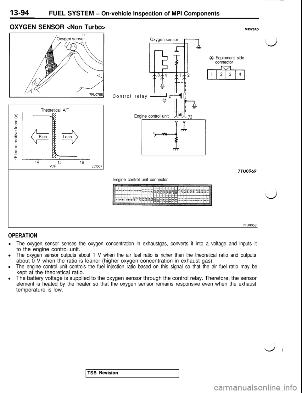
OXYGEN SENSOR
7FUO786
Theoretical A/F
14
1516A/FEClOOiControl relay
2 dI 1:
Engine control unit
@ Equipment side
connector
7FUO969
Engine control unit connector
7FUO653
OPERATION
lThe oxygen sensor senses the oxygen concentration in exhaustgas, converts it into a voltage and inputs itto the engine control unit.
l
The oxygen sensor outputs about 1 V when the air fuel ratio is richer than the theoretical ratio and outputsabout 0 V when the ratio is leaner (higher oxygen concentration in exhaust gas).
lThe engine control unit controls the fuel injection ratio based on this signal so that the air fuel ratio may bekept at the theoretical ratio.
lThe battery voltage is supplied to the oxygen sensor through the control relay. Therefore, the sensor
element is heated by the heater so that the oxygen sensor remains responsive even when the exhausttemperature is low.
‘d i
TSB
RtkisionI