MITSUBISHI 3000GT 1991 Service Manual
Manufacturer: MITSUBISHI, Model Year: 1991, Model line: 3000GT, Model: MITSUBISHI 3000GT 1991Pages: 1146, PDF Size: 76.68 MB
Page 221 of 1146
FUEL SYSTEM - On-vehicle Inspection of MPI Components
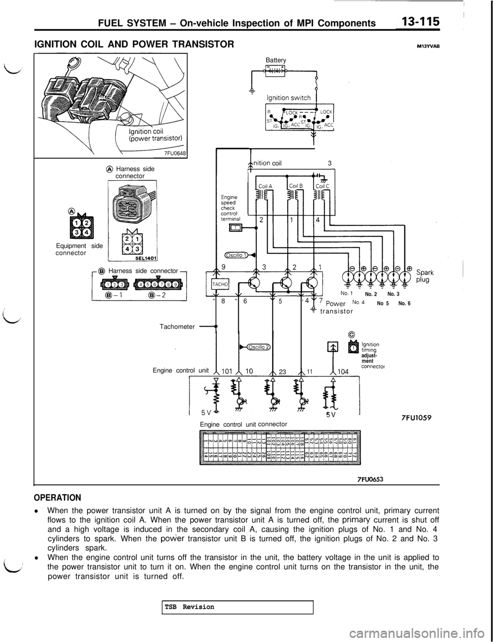
IGNITION COIL AND POWER TRANSISTOR
MlBYVABEquipment side
connector@ Harness side
connector@ Harness side connector
Tachometer
-1Battery
/gnition coil1 3
Engine control unit
\/\/\IAL“8 “6.,,523No. 2No. 3
No 5No. 6
* transistor
5Y
lgnltlontamingadjust-
mentconnectof
11104
d
w5V
7FU1059Engine control unitconnector
7FUO453
OPERATION
lWhen the power transistor unit A is turned on by the signal from the engine control unit, primary current
flows to the ignition coil A. When the power transistor unit A is turned off, the primaty current is shut off
and a high voltage is induced in the secondary coil A, causing the ignition plugs of No. 1 and No. 4
cylinders to spark. When the
power transistor unit B is turned off, the ignition plugs of No. 2 and No. 3
cylinders spark.
L
lWhen the engine control unit turns off the transistor in the unit, the battery voltage in the unit is applied to
the power transistor unit to turn it on. When the engine control unit turns on the transistor in the unit, the
power transistor unit is turned off.
TSB Revision
Page 222 of 1146
13-116FUEL SYSTEM - 0
n-vehicle Inspection of MPI Components
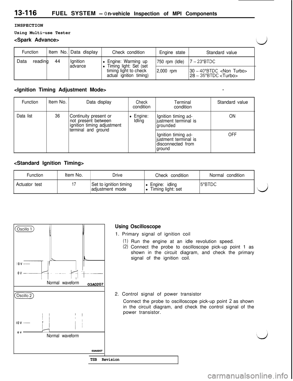
INSPECTION
Using Multi-use Tester
(d
FunctionItem No. Data displayCheck condition
Engine state
Standard valueData reading 44
Ignitionadvancel Engine: Warming up
750 rpm (Idle)7 - 23”BTDCl Timing light: Set (settiming light to check2,000 rpm30 - 40”BTDC
‘
Function
Data listItem No.Data displayCheckTerminalStandard value
condition
condition
36Continuity present or
not present betweenl Engine:
IdlingIgnition timing ad-ON
ignition timing adjustmentjustment terminal isterminal and groundgrounded
Ignition timing ad-OFFjustment terminal is
disconnected from
ground
Function
Actuator testItem No.
DriveCheck conditionNormal condition
17Set to ignition timingl Engine: idling5”BTDCadjustment model Timing light: set\
($Gizi)
IJ
\LIOV _
ovep~,. ..~_~.~ fA t---.-
I
Normal waveform03AO207
(
j /’ II
IOV _I ’/
/ 1ovIJ
Normal waveform
Using Oscilloscope1. Primary signal of ignition coil
(I) Run the engine at an idle revolution speed.
(2) Connect the probe to oscilloscope pick-up point 1 as
shown in the circuit diagram, and check the primary
signal of the ignition coil.
2. Control signal of power transistor
Connect the probe to oscilloscope pick-up point
2 as shown
in the circuit diagram, and check the control signal of the
power transistor.
TSB Revision
Page 223 of 1146
FUEL SYSTEM - On-vehicle Inspection of MPI Components13-117
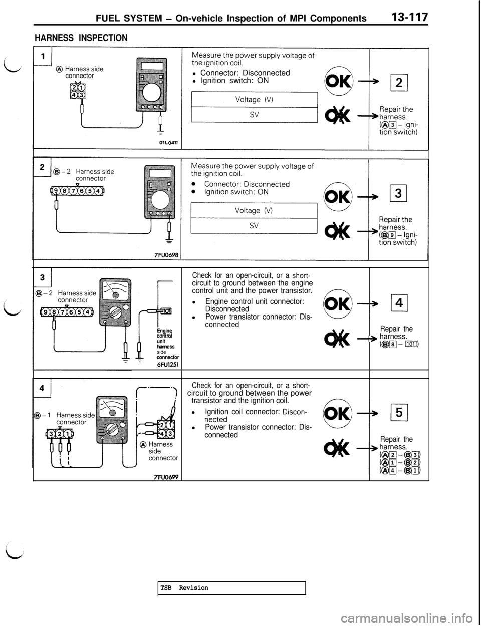
HARNESS INSPECTION
connectorl Connector: Disconnected
l Ignition switch: ON
Check for an open-circuit, or a short-
P
circuit to ground between the engine
control unit and the power transistor.l
Engine control unit connector:
Disconnectedl
Power transistor connector: Dis-connectedEngineRepair thecontrolunit-+ harness.harness(@@J-1101/)stdeconnector
T6FU1251
Check for an open-circuit, or a short-circuit to ground between the power
transistor and the ignition coil.l
Ignition coil connector: Discon-netted
l
Power transistor connector: Dis-
connected
Repair the
7FUO699
TSB Revision
Page 224 of 1146
13-118FUEL SYSTEM- On-vehicle Inspection of MPI Components
connector
7FUO700
7FUO701
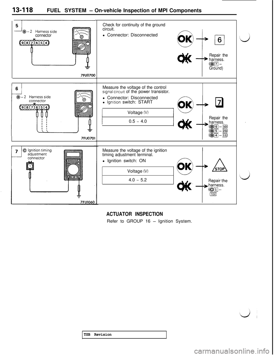
Check for continuity of the ground
circuit.
(1Il Connector: Disconnected
Repair the
harness.@pJ
-Ground)
Measure the voltage of the controlslgnal circuit of the power transistor.l Connector: Disconnected
l
lgnrtion switch: START
Voltage
(VI0.5
- 4.0
f
q7
Repair the
harness.
Measure the voltage of the ignition
timinq adiustment terminal.
- _l Ignition switch: ON
Voltage
(V)4.0
- 5.2
ACTUATOR INSPECTIONRefer to GROUP 16
- Ignition System.
TSB Revision
Page 225 of 1146
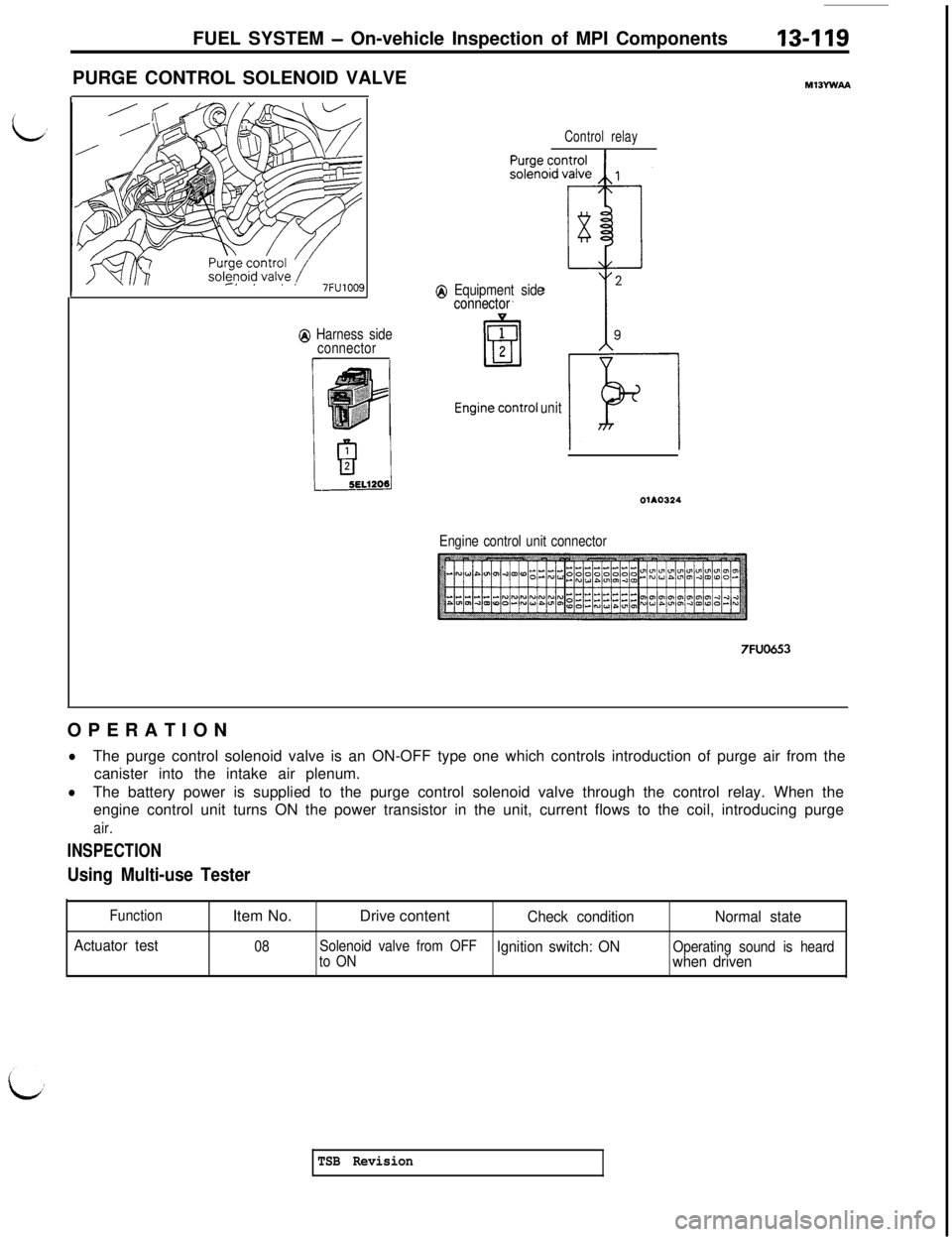
FUEL SYSTEM - On-vehicle Inspection of MPI Components13-119PURGE CONTROL SOLENOID VALVE
Q Harness side
connector
I
Control relay
@ Equipment side
connector connector
unit
OlAO324
Engine control unit connector
7FUO653OPERATION
lThe purge control solenoid valve is an ON-OFF type one which controls introduction of purge air from the
canister into the intake air plenum.
lThe battery power is supplied to the purge control solenoid valve through the control relay. When the
engine control unit turns ON the power transistor in the unit, current flows to the coil, introducing purge
air.
INSPECTION
Using Multi-use Tester
Function
Actuator testItem No.Drive content
Check conditionNormal state
08Solenoid valve from OFFIgnition switch: ONOperating sound is heard
to ONwhen driven
TSB Revision
Page 226 of 1146
13-120FUEL SYSTEM - On-vehicle Inspection of MPI Components
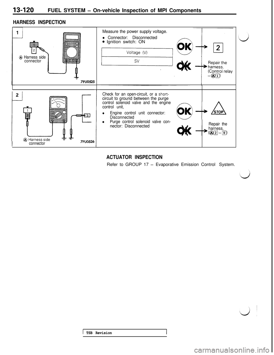
HARNESS INSPECTION
@ Harness side
connector
T7FUO525
I -connector57FUO526
1
Measure the power supply voltage.
l Connector: Disconnected0 Ignition switch: ON
Check for an open-circuit, or a short-circuit to ground between the purgecontrol solenoid valve and the engine
control unit,
lEngine control unit connector:
Disconnected@-+A
lPurge control solenoid valve con-nector: DisconnectedRepair the
harness.
ACTUATOR INSPECTIONRefer to GROUP 17
- Evaporative Emission Control System.
1 TSB Revision1
Page 227 of 1146
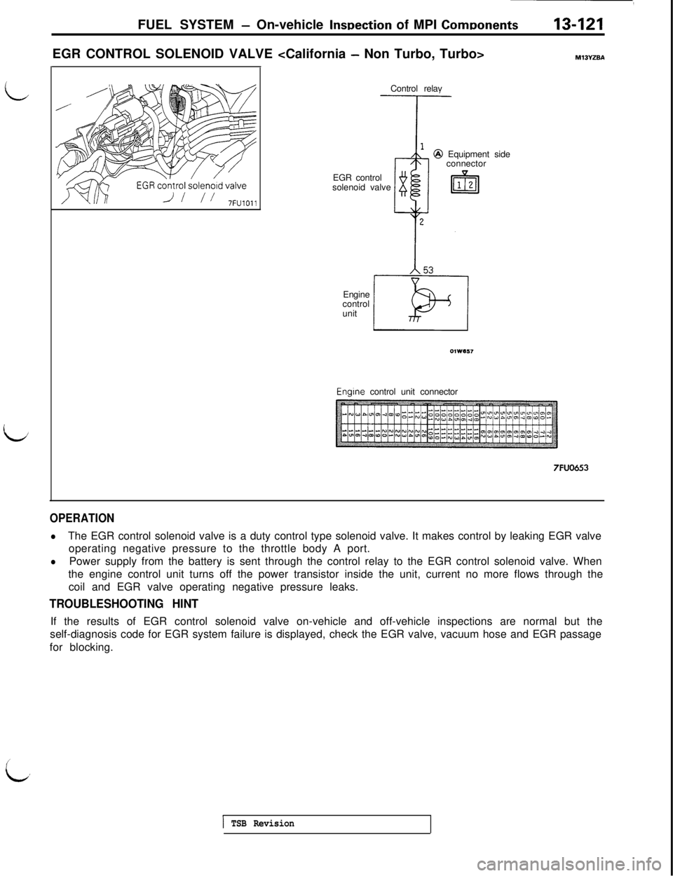
FUEL SYSTEM - On-vehicle lnwection of MPI ComDonents13-121
LEGR CONTROL SOLENOID VALVE
EGR control
solenoid valve@ Equipment side
connector
Engine
control
unitEngine control unit connector
7FUO653
OPERATION
lThe EGR control solenoid valve is a duty control type solenoid valve. It makes control by leaking EGR valve
operating negative pressure to the throttle body A port.
lPower supply from the battery is sent through the control relay to the EGR control solenoid valve. When
the engine control unit turns off the power transistor inside the unit, current no more flows through the
coil and EGR valve operating negative pressure leaks.
TROUBLESHOOTING HINTIf the results of EGR control solenoid valve on-vehicle and off-vehicle inspections are normal but the
self-diagnosis code for EGR system failure is displayed, check the EGR valve, vacuum hose and EGR passage
for blocking.
c.
1 TSB Revision
Page 228 of 1146
13-122FUEL SYSTEM - On-vehicle Inspection of MPI Components
INSPECTIONUsing Multi-use Tester
Function
Actuator testItem No.
Drive content
Check condition
Normal state
10Change solenoid valve
from OFF to ON stateIgnition switch: ONOperating sound is heardwhen driven
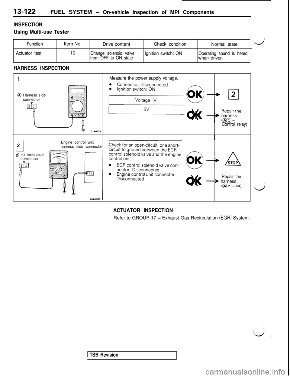
HARNESS INSPECTION
1
@ Harness side
connector
Measure the power supply voltage.
Y01105*4Engine control unit
harness side connector
Control relay)
Repair the
-S harness.C@vJ-~)
d
Ls
ACTUATOR INSPECTIONRefer to GROUP 17
- Exhaust Gas Recirculation (EGR) System.
1 TSB Revision
Page 229 of 1146
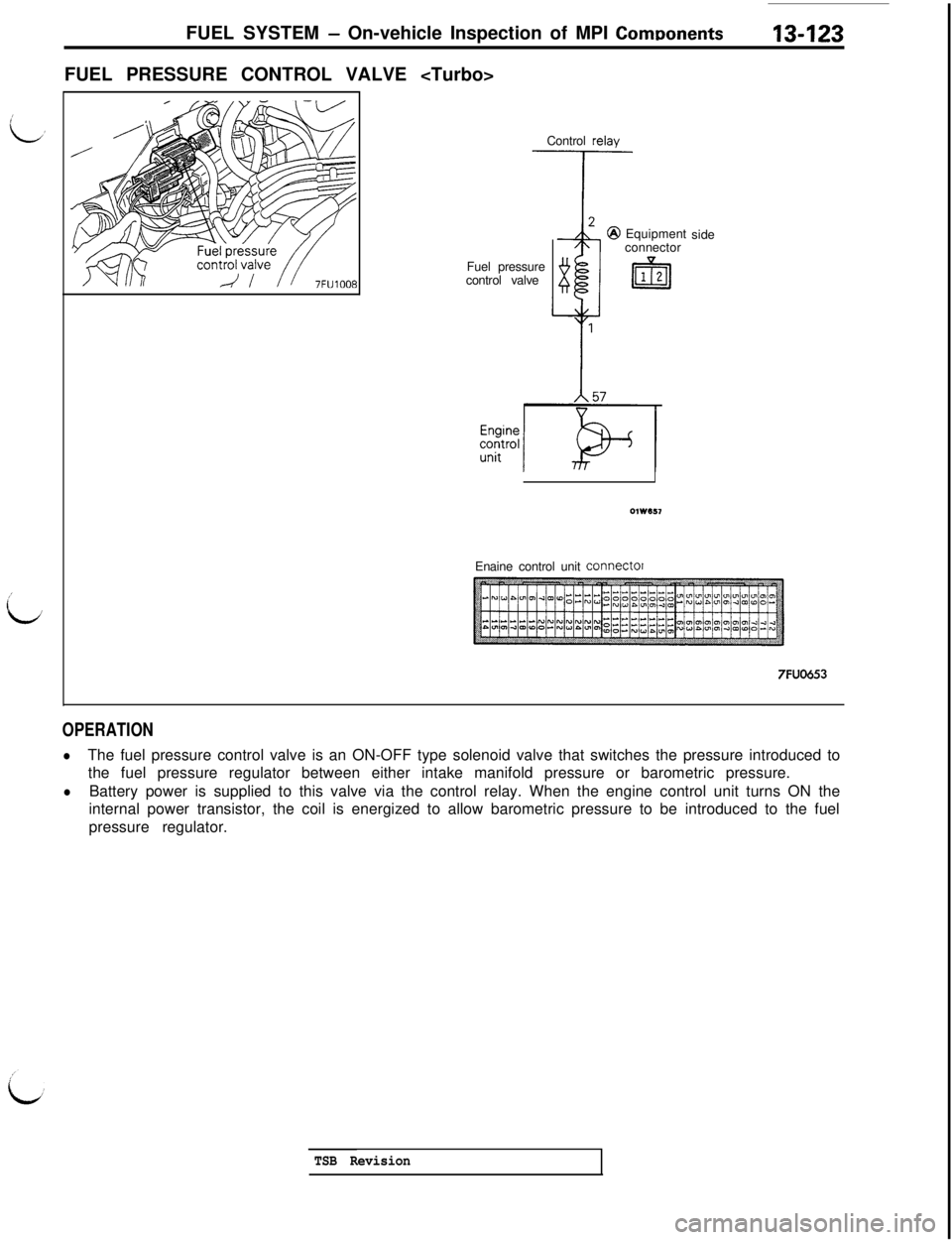
FUEL SYSTEM - On-vehicle Inspection of MPI ComDonents13-123FUEL PRESSURE CONTROL VALVE
Control relay
Fuel pressure
control valveEquipment
connectorside
Enaine control unit
connector
7FUO653
OPERATION
lThe fuel pressure control valve is an ON-OFF type solenoid valve that switches the pressure introduced to
the fuel pressure regulator between either intake manifold pressure or barometric pressure.
lBattery power is supplied to this valve via the control relay. When the engine control unit turns ON the
internal power transistor, the coil is energized to allow barometric pressure to be introduced to the fuel
pressure regulator.
TSB Revision
Page 230 of 1146
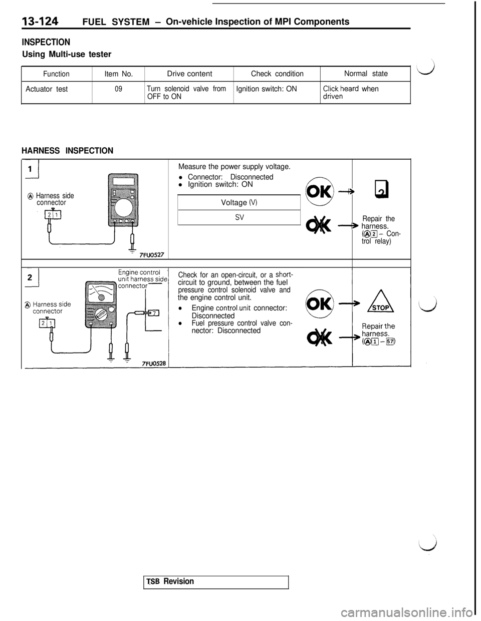
13-124FUEL SYSTEM -On-vehicle Inspection of MPI Components
INSPECTIONUsing Multi-use tester
Function
Actuator testItem No.Drive content
Check conditionNormal state
09Turn solenoid valve fromIgnition switch: ONOFF to ONr%;reard when
HARNESS INSPECTION
@ Harness side
connector
Measure the power supply voltage.
l Connector: Disconnectedl Ignition switch: ON
Voltage
(V)2-* q
SVRepair thei* harness.(@m - Con-
trol relay)
7FUO527
Check for an open-circuit, or a short-circuit to ground, between the fuelpressure control solenoid valve andthe engine control unit.
lEngine controLunit connector:
Disconnected
lFuel pressure control valve con-nector: Disconnected
TSB Revision