MITSUBISHI 3000GT 1991 Service Manual
Manufacturer: MITSUBISHI, Model Year: 1991, Model line: 3000GT, Model: MITSUBISHI 3000GT 1991Pages: 1146, PDF Size: 76.68 MB
Page 201 of 1146
FUEL SYSTEM - 0
n-vehicle Inspection of MPI Components13-95
TROUBLESHOOTING HINTSHint 1: Poor cleaning of exhaust gas will result if the oxygen sensor fails.
Hint 2:If the oxygen sensor check has resulted normal but the sensor output voltage is out of specification,
troubles of parts related to air fuel ratio control system are suspected.
[Examples]
(1) Faulty injector
(2) Air leaking into the intake manifold through gasket gap, etc.
(3) Faulty air flow sensor, intake air temperature sensor, barometric pressure sensor,’ engine
Data readingcoolant temperature sensor
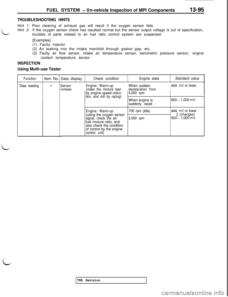
INSPECTIONUsing Multi-use Tester
FunctionItem No. Data displayCheck conditionEngine stateStandard value
11SensorvoltaceEngine: Warm-upWhen sudden200 mV or lower
(make the mixture leandeceleration from
L
by engine speed reduc-4,000 rpm
tion, and rich by racing)
When engine is600-1,000 mV
suddenly raced
Engine: Warm-up700 rpm (Idle)
400 mV or lower
(using the oxygen sensorsignal, check the air/2,000 rpm,,,5-‘$-$-;3
fuel mixture ratio, and
also check the condition
of control by the engine
control unit)
TSB Revision
Page 202 of 1146
13-96FUEL SYSTEM - 0n-vehicle Inspection of MPI Components
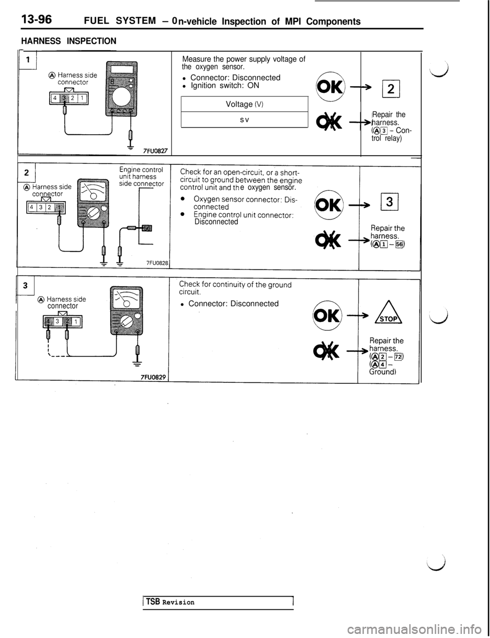
HARNESS INSPECTION
rMeasure the power supply voltage ofthe oxygen sensor.l Connector: Disconnected
l Ignition switch: ON
Voltage
(V)sv
Repair the
harness.
(@m - Con-trol relay)
- 7FUO827
e oxygen sensor.
Disconnected
connectorl Connector: Disconnected
1 TSB Revision
Page 203 of 1146
FUEL SYSTEM - On-vehicle Inspection of MPI ComDonents13-97
,
7FU1014
7FUlOl5
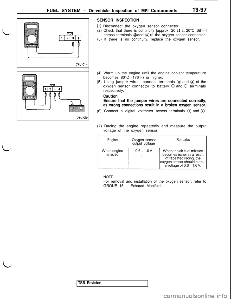
SENSOR INSPECTION
(1) Disconnect the oxygen sensor connector.
(2) Check that there is continuity [approx. 20
IR at 20°C (68”F)jacross terminals @and
@of the oxygen sensor connector.
(3) If there is no continuity, replace the oxygen sensor.
(4) Warm up the engine until the engine coolant temperature
becomes 80°C (176°F) or higher.
(5) Using jumper wires, connect terminals @ and @ of the
oxygen sensor connector to battery
0 and 0 terminals
respectively.
Caution
Ensure that the jumper wires are connected correctly,
as wrong connections result in a broken oxygen sensor.(6) Connect a digital voltmeter across terminals @ and
0.(7) Racing the engine repeatedly and measure the output
voltage of the oxygen sensor.
EngineOxygen sensor
output voltageRemarks
NOTEFor removal and installation of the oxygen sensor, refer to
GROUP 15
- Exhaust Manifold.
TSB Revision
Page 204 of 1146
FUEL SYSTEM - 0
n-vehicleInspection of MPI Components
OXYGEN SENSOR
M13YHAA2I
2
2-J
_ Fr;;syn m-wr
li \\\Oxygen sensor
I7FU1004Theoretical A/F@Oxygen sensor
(rear)Oxygen sensor
Equipment side(front)@,ConnectorEquipment side:connectorf-l -1
Lonrrol relay--Control relay
Engine control unit 56
141516PJFEC1007Engine control unit connector
7FUO453
I
I7FU1016@ Harness side@ Harness side
Connector
connector
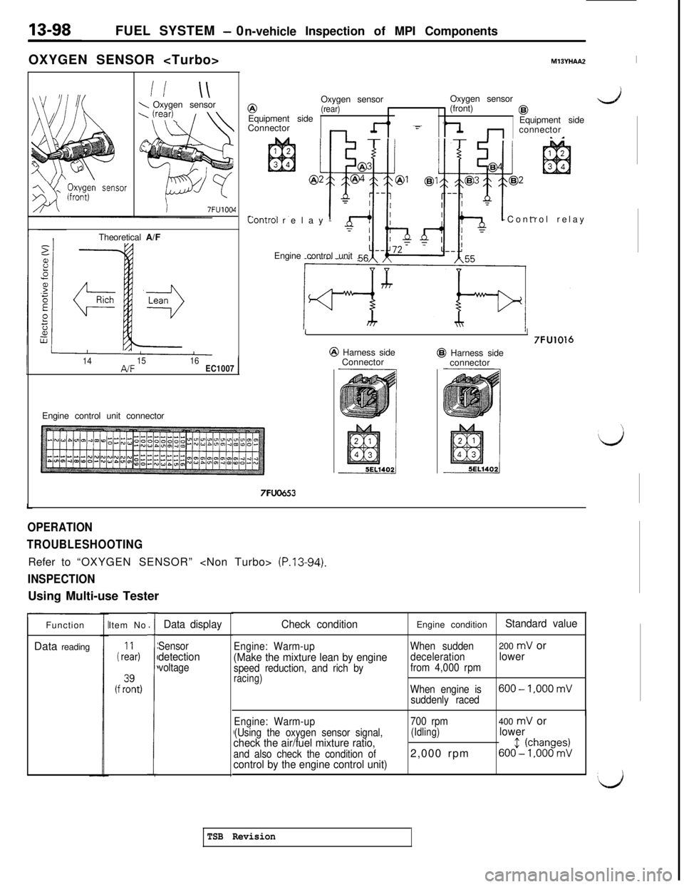
OPERATION
TROUBLESHOOTINGRefer to “OXYGEN SENSOR”
(P.13-94).
INSPECTIONUsing Multi-use Tester
Function
Data readingItem No.
i rL&
(f fzt,
,
1
Data display
Sensordetectionvoltage
Check condition
Engine: Warm-up(Make the mixture lean by enginespeed reduction, and rich byracing)Engine condition
Standard value
When sudden200 mV or
decelerationlowerfrom 4,000 rpm
When engine is
600-1.000 mV
suddenly raced
./
Engine: Warm-up
(Using the oxygen sensor signal,
check the air/fuel mixture ratio,and also check the condition ofcontrol by the engine control unit)
700 rpm(Idling)2,000 rpm400 mV orlower
6()(f--(~jbaono9~;
‘d
TSB Revision
Page 205 of 1146
1
FUEL SYSTEM- On-vehicle InsDection of MPI ComDonents13-99
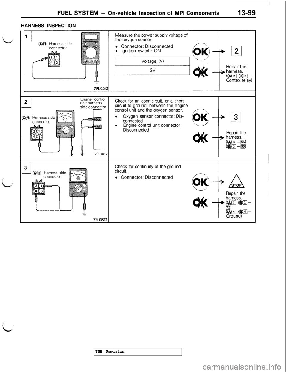
HARNESS INSPECTIONl Connector: Disconnected
l Ignition switch: ON
Engine control
Check for an open-circuit, or a short-circuit to ground, between the engine
control unit and the oxygen sensor.
lOxygen sensor connector: Dis-connectedlEngine control unit connector:
Disconnected
Repair the-+ harness.
3Check for continuity of the ground
- @@
Harness sidecircuit.l Connector: Disconnected
Repair the
harness.
7FUO512
TSB Revision
Page 206 of 1146
13-100FUEL SYSTEM - 0
n-vehicleInspection of MPI Components
SENSOR INSPECTION
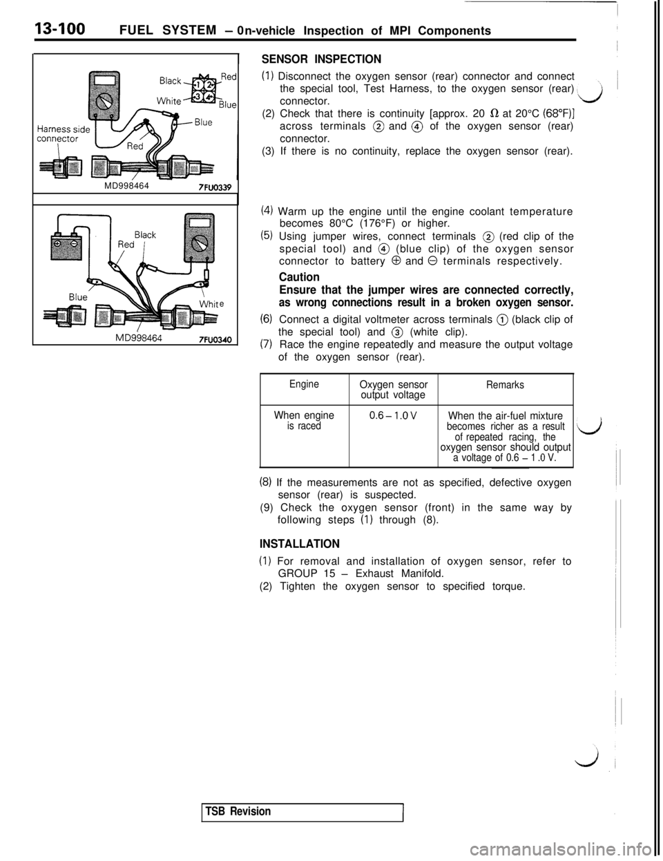
(1) Disconnect the oxygen sensor (rear) connector and connect
the special tool, Test Harness, to the oxygen sensor (rear)
connector.
MD998464
7FUO339
e
MD9584647FUO340(2) Check that there is continuity [approx. 20
R at 20°C (68”F)Iacross terminals @ and @ of the oxygen sensor (rear)
connector.
(3) If there is no continuity, replace the oxygen sensor (rear).
(4) Warm up the engine until the engine coolant temperature
becomes 80°C (176°F) or higher.
(5) Using jumper wires, connect terminals @ (red clip of the
special tool) and @ (blue clip) of the oxygen sensor
connector to battery
0 and 0 terminals respectively.
Caution
Ensure that the jumper wires are connected correctly,
as wrong connections result in a broken oxygen sensor.
(6)Connect a digital voltmeter across terminals @ (black clip of
(7)the special tool) and @ (white clip).
Race the engine repeatedly and measure the output voltage
of the oxygen sensor (rear).
EngineOxygen sensor
output voltageRemarks
When engineis raced0.6-l.OVWhen the air-fuel mixturebecomes richer as a result
of repeated racing, the
oxygen sensor should outputa voltage of 0.6 - 1 .O V.
(8) If the measurements are not as specified, defective oxygen
sensor (rear) is suspected.
(9) Check the oxygen sensor (front) in the same way by
following steps
(I) through (8).
INSTALLATION
(1) For removal and installation of oxygen sensor, refer to
GROUP 15
- Exhaust Manifold.
(2) Tighten the oxygen sensor to specified torque.
TSB Revision
Page 207 of 1146
FUEL SYSTEM - On-vehicle Inspection of MPI Components13-101INJECTORS
M13YTAC2
IInjectorII\- 7FUO803
7FI
FuelFilter
@Injection
7FUO83:2Connector for
rear bank
Engine control unit7FUO833
Engine control unit connector
7FUO653
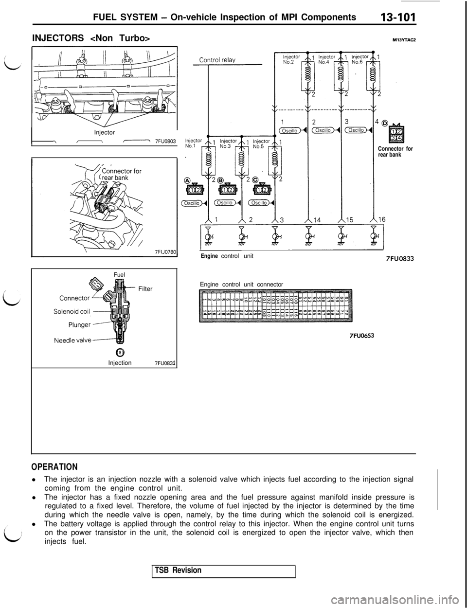
OPERATIONlThe injector is an injection nozzle with a solenoid valve which injects fuel according to the injection signal
coming from the engine control unit.
lThe injector has a fixed nozzle opening area and the fuel pressure against manifold inside pressure is
regulated to a fixed level. Therefore, the volume of fuel injected by the injector is determined by the time
during which the needle valve is open, namely, by the time during which the solenoid coil is energized.
lThe battery voltage is applied through the control relay to this injector. When the engine control unit turns
on the power transistor in the unit, the solenoid coil is energized to open the injector valve, which then
injects fuel.
TSB Revision
Page 208 of 1146
13-102FUEL SYSTEM - On-vehicle Inspection of MPI Components
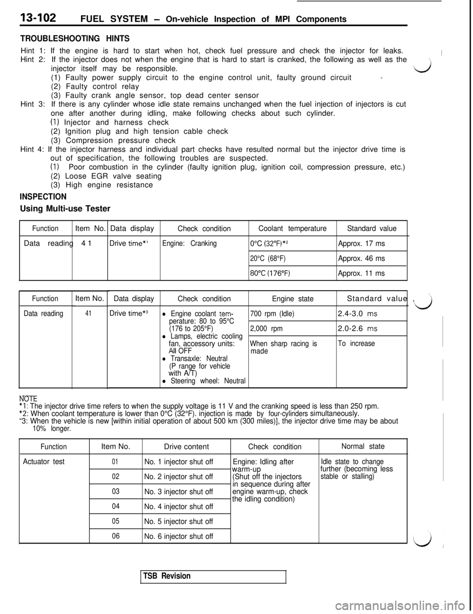
TROUBLESHOOTING HINTSHint 1: If the engine is hard to start when hot, check fuel pressure and check the injector for leaks.
Hint 2:If the injector does not when the engine that is hard to start is cranked, the following as well as the
Iinjector itself may be responsible.
(1) Faulty power supply circuit to the engine control unit, faulty ground circuit
\-J
-(2) Faulty control relay
Hint 3:(3) Faulty crank angle sensor, top dead center sensor
If there is any cylinder whose idle state remains unchanged when the fuel injection of injectors is cut
one after another during idling, make following checks about such cylinder.
(1) Injector and harness check
(2) Ignition plug and high tension cable check
(3) Compression pressure check
Hint 4: If the injector harness and individual part checks have resulted normal but the injector drive time is
out of specification, the following troubles are suspected.
(1)Poor combustion in the cylinder (faulty ignition plug, ignition coil, compression pressure, etc.)
(2) Loose EGR valve seating
(3) High engine resistance
INSPECTIONUsing Multi-use Tester
FunctionItem No. Data displayCheck conditionCoolant temperatureStandard valueData reading 41
Drive time”’Engine: Cranking0°C (32”F)*zApprox. 17 ms
20°C (68°F)Approx. 46 ms
8O"C(176"F)Approx. 11 ms
Function
Data readingItem No.Data display
41Drive time*3l Engine coolant tem-perature: 80 to 95°C700 rpm (Idle)2.4-3.0 ms
(176 to 205°F)2,000 rpm2.0-2.6
msl Lamps, electric coolingfan, accessory units:When sharp racing isTo increaseAll OFF
madel Transaxle: Neutral
(P range for vehicle
with A/T)l Steering wheel: Neutral
Check conditionEngine stateStandard value ,
.---NOTE“I : The injector drive time refers to when the supply voltage is 11 V and the cranking speed is less than 250 rpm.*2: When coolant temperature is lower than 0°C (32°F). injection ismade by four-cylinders.---simultaneously.
“3: When the vehicle is new [within initial operation of about 500 km (300 miles)], the injector drive time may be about
10% longer.
Function
Actuator testItem No.
Drive content
Check conditionNormal state
01No. 1 injector shut offEngine: Idling afterIdle state to change
02No. 2 injector shut offwarm-up
(Shut off the injectorsfurther (becoming less
in sequence during afterstable or stalling)
03
No. 3 injector shut offengine warm-up, check
04No. 4 injector shut offthe idling condition)
05No. 5 injector shut off
06No. 6 injector shut off
TSB Revision
Page 209 of 1146
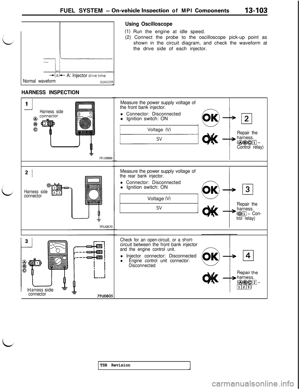
FUEL SYSTEM- Ori-vehicle lnwection of MPI ComDonents13403
+/A+ A: Injector drive time
Normal waveform03A0201
HARNESS INSPECTION
--J1
Harness side
7FlJO669
* I
@
Harness side
connector
1 HarnessJPside =connector7FUO805
Using Oscilloscope
(1) Run the engine at idle speed.
(2) Connect the probe to the oscilloscope pick-up point as
shown in the circuit diagram, and check the waveform at
the drive side of each injector.
Measure the power supply voltage of
the front bank injector.
-
l Connector: Disconnectedl Ignition switch: ON
1
Repair the
harness.
(m-Control relay)
Measure the power supply voltage ofthe rear bank injector.
l Connector: Disconnectedl Ignition switch: ON
Voltage
(VI
svRepair the
harness.
(m - Con-
trol relay)
Check for an open-circuit, or a
short-circuit between the front bank injectorand the engine control unit.
l Injector connector: DisconnectedlEngine control unit connector:
Disconnected
id
TSB Revision
Page 210 of 1146
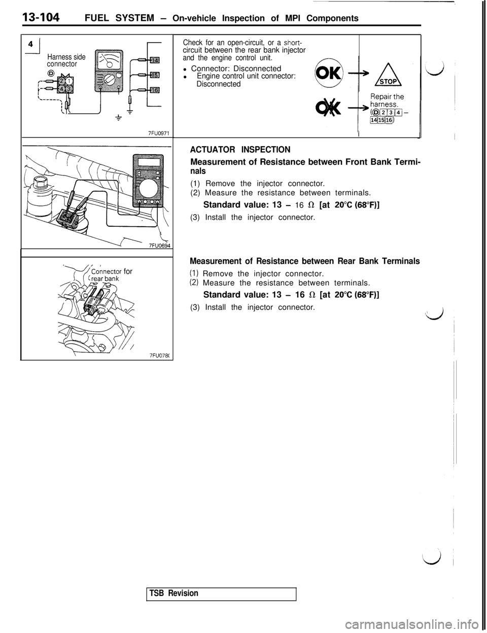
13-104FUEL SYSTEM - On-vehicle Inspection of MPI Components
-l4Harness side
connector
L----.[ Q1J
7FUO971
‘Y-4 ’onnector for
7FUO78C
Check for an open-circuit, or a short-circuit between the rear bank injectorand the engine control unit.l Connector: Disconnected
l
Engine control unit connector:
Disconnected
I
ACTUATOR INSPECTIONMeasurement of Resistance between Front Bank Termi-
nals(1) Remove the injector connector.
(2) Measure the resistance between terminals.
Standard value: 13
- 16 il [at 20°C (68”F)](3) Install the injector connector.
Measurement of Resistance between Rear Bank Terminals
(I) Remove the injector connector.
(2) Measure the resistance between terminals.
Standard value: 13
- 16 Q [at 20°C (68”F)](3) Install the injector connector.
\
TSB Revision