MITSUBISHI 3000GT 1991 Service Manual
3000GT 1991
MITSUBISHI
MITSUBISHI
https://www.carmanualsonline.info/img/19/57085/w960_57085-0.png
MITSUBISHI 3000GT 1991 Service Manual
Trending: tow bar, fuse diagram, fuse chart, clock setting, radiator, fuel additives, wheel bolts
Page 231 of 1146
FUEL SYSTEM - On-vehicle Inspection of MPI Components13-125
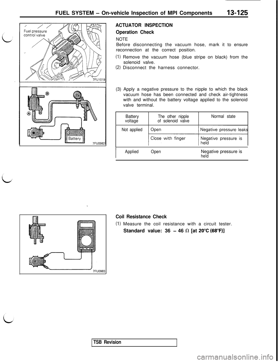
ACTUATOR INSPECTION
Operation Check
NOTEBefore disconnecting the vacuum hose, mark it to ensure
reconnection at the correct position.
(1) Remove the vacuum hose (blue stripe on black) from the
solenoid valve.
(2) Disconnect the harness connector.
(3) Apply a negative pressure to the nipple to which the black
vacuum hose has been connected and check air-tightness
with and without the battery voltage applied to the solenoid
valve terminal.
BatteryvoltageThe other nipple
of solenoid valveNormal state
Not applied
qj
I
AppliedOpenNegative pressure isheld
Coil Resistance Check
(I) Measure the coil resistance with a circuit tester.
Standard value: 36
- 46 R [at 20°C (68”F)]
TSB Revision
Page 232 of 1146
13-126FUEL SYSTEM - On-vehicle Inspection of MPI Components
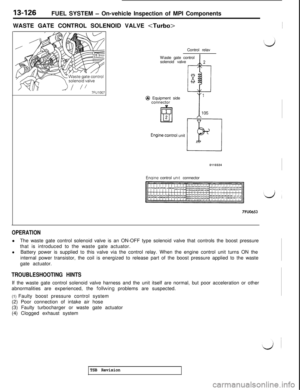
WASTE GATE CONTROL SOLENOID VALVE
7FU1007Control relav
Waste gate control
solenoid valve
Q Equipment side
connector
unit
0110324Enqlne control unit connector
7FUO653
OPERATIONlThe waste gate control solenoid valve is an ON-OFF type solenoid valve that controls the boost pressure
that is introduced to the waste gate actuator.
lBattery power is supplied to this valve via the control relay. When the engine control unit turns ON the
internal power transistor, the coil is energized to release part of the boost pressure applied to the waste
gate actuator.
TROUBLESHOOTING HINTSIf the waste gate control solenoid valve harness and the unit itself are normal, but poor acceleration or other
abnormalities are experienced, the
follwing problems are suspected.
(1) Faulty boost pressure control system
(2) Poor connection of intake air hose
(3) Faulty turbocharger or waste gate actuator
(4) Clogged exhaust system
TSB Revision
Page 233 of 1146
FUEL SYSTEM - On-vehicle Inspection of MPI Components'13-127
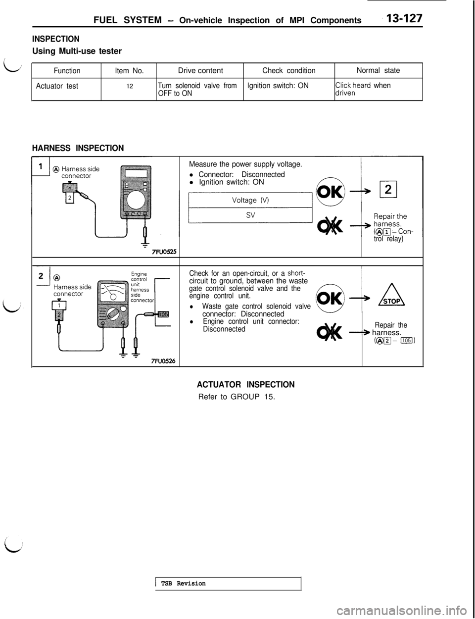
INSPECTIONUsing Multi-use tester
LFunctionItem No.Drive contentCheck conditionNormal state
Actuator test12
Turn solenoid valve fromIgnition switch: ONOFF to ON
CliZli~,“eard when
HARNESS INSPECTION
Measure the power supply voltage.
l Connector: Disconnectedl Ignition switch: ON
trol relay)
7FUO525
Check for an open-circuit, or a short-circuit to ground, between the wastegate control solenoid valve and the
engine control unit.
lWaste gate control solenoid valveconnector: DisconnectedlEngine control unit connector:
DisconnectedRepair the
-+ harness.
(@m- ml)
7FUO526
ACTUATOR INSPECTIONRefer to GROUP 15.
1 TSB Revision
Page 234 of 1146
13-128FUEL SYSTEM - On-vehicle Inspection of MPI Components
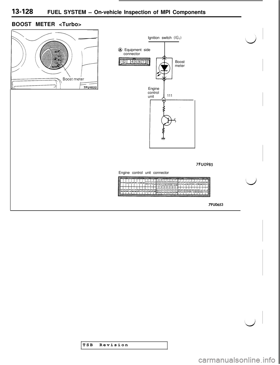
BOOST METER
Ignition switch
(IG,)@ Equipment side
connector
Boost
meter
Engine
control
unit
111
i-F7FUO985
Engine control unit connector
TSB Revision
Page 235 of 1146
FUEL SYSTEM - On-vehicle Inspection of MPI Components13-129
i
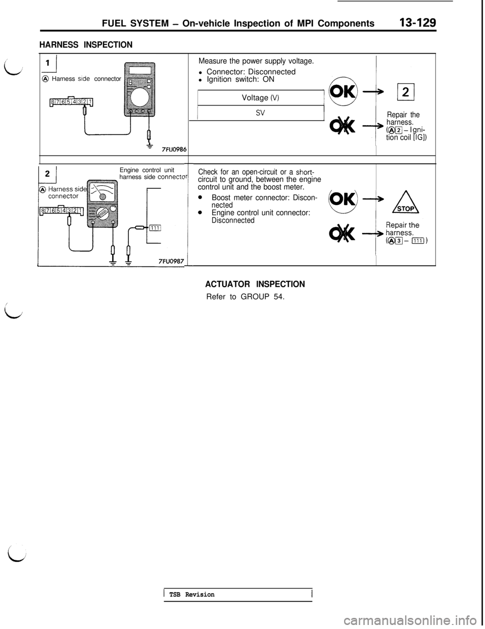
HARNESS INSPECTION@ Harness side connector
*7FUO986Engine control unit
harness side
connect0r
1
Measure the power supply voltage.l Connector: Disconnected
l Ignition switch: ON
Voltage
(V)
svRepair the
harness.
(@I@-- Ini-tion coil9IG])
Check for an open-circuit or a short-circuit to ground, between the engine
control unit and the boost meter.
Boost meter connector: Discon-
nectedEngine control unit connector:Disconnected
ACTUATOR INSPECTIONRefer to GROUP 54.
1 TSB Revision
Page 236 of 1146
13-130FUEL SYSTEM - On-vehicle Inspection of MPI Components
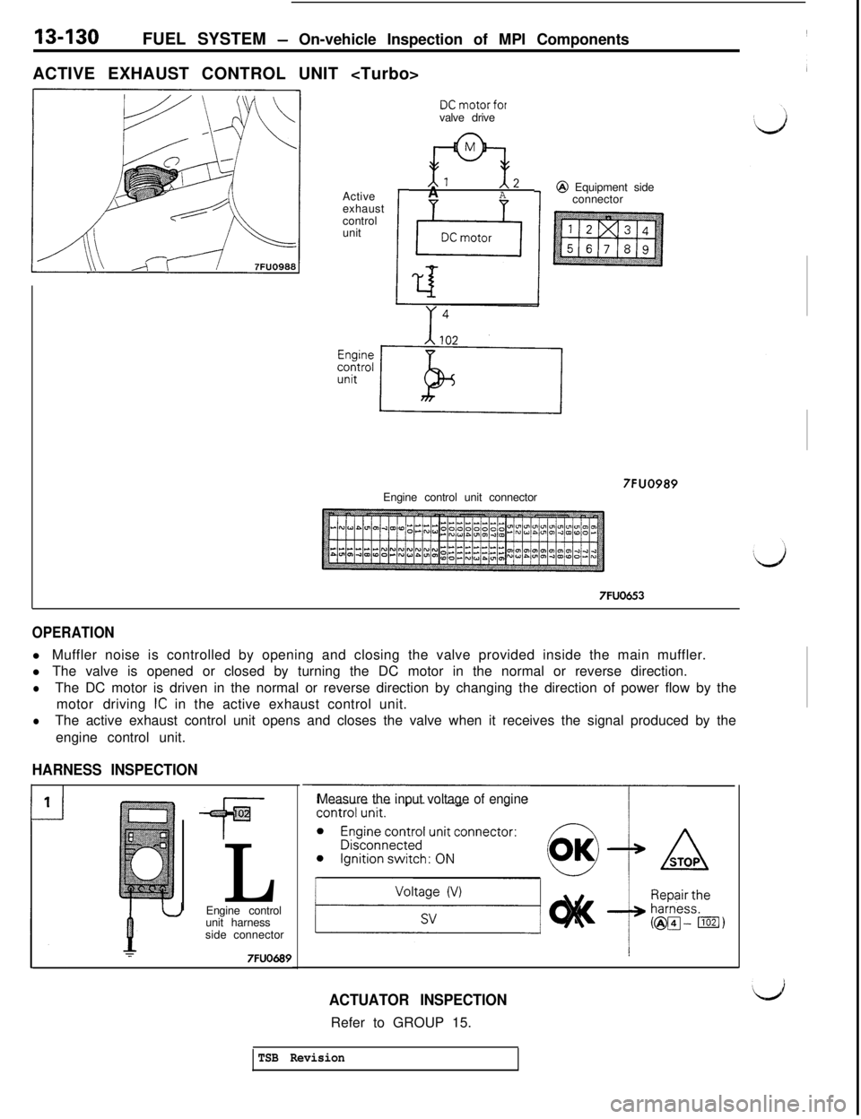
ACTIVE EXHAUST CONTROL UNIT
Active
exhaust
control
unit
I
DCmotorforvalve drive
Al 12AA@ Equipment side
connector
Engine control unit connector
7FUO989
7FUO653
OPERATIONl Muffler noise is controlled by opening and closing the valve provided inside the main muffler.
l The valve is opened or closed by turning the DC motor in the normal or reverse direction.
lThe DC motor is driven in the normal or reverse direction by changing the direction of power flow by the
motor driving
IC in the active exhaust control unit.
lThe active exhaust control unit opens and closes the valve when it receives the signal produced by the
engine control unit.
HARNESS INSPECTION
0
FL
I’ JEngine control
unit harness
side connector
7FUO689I
Measure the input voltage of engine
ACTUATOR INSPECTIONRefer to GROUP 15.
TSB Revision
Page 237 of 1146
FUEL SYSTEM - On-vehicle lnwection of MPI ComDonents13-131
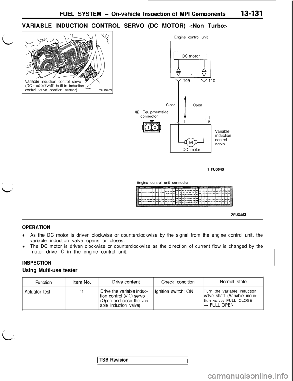
iVARIABLE INDUCTION CONTROL SERVO (DC MOTOR) Variable induction control servo
Y(DC motor)(with built-in induction/-control valve oosition sensor)-7Fllfl807Engine control unit
Close
connector
,\ IOpen@ Equipmentside1,,I2DC motorVariable
induction
control
servo
1 FU0646
Engine control unit connector
7FUO653
OPERATION
lAs the DC motor is driven clockwise or counterclockwise by the signal from the engine control unit, the
variable induction valve opens or closes.
lThe DC motor is driven clockwise or counterclockwise as the direction of current flow is changed by the
motor drive
IC in the engine control unit.
INSPECTIONUsing Multi-use tester
Function
Actuator testItem No.Drive content
Check conditionNormal state
11Drive the variable induc-Ignition switch: ONTurn the variable inductiontion control (MC) servovalve shaft (Variable induc-
(Open and close the
vari-tion valve: FULL CLOSEable induction valve)+ FULL OPEN
1 TSB RevisionI
Page 238 of 1146
13-132
IFUEL SYSTEM
- 0
n-vehicle Inspection of MPI Components
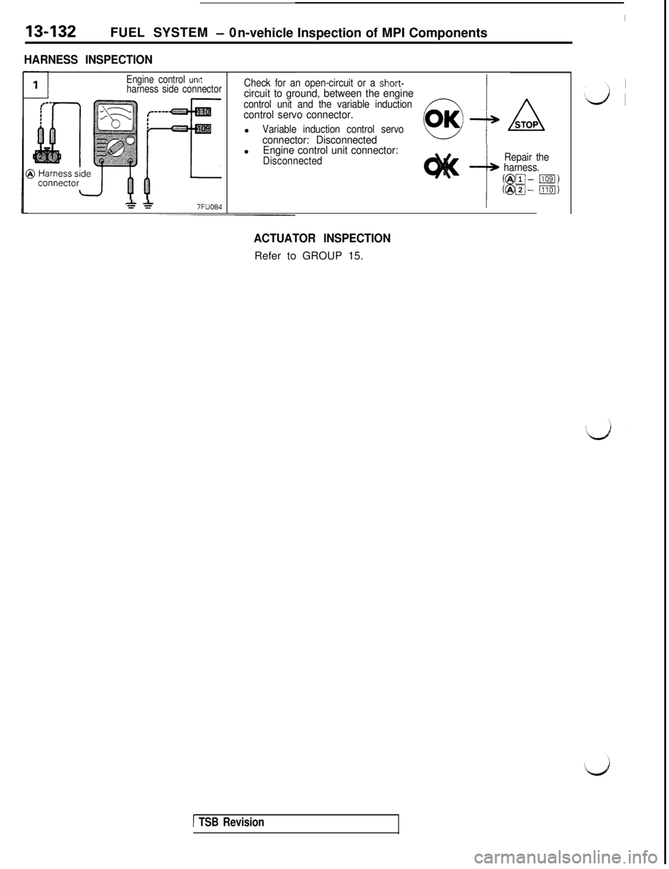
HARNESS INSPECTION
Engine control unitharness side connectorCheck for an open-circuit or a short-circuit to ground, between the enginecontrol unit and the variable inductioncontrol servo connector.l
Variable induction control servoconnector: DisconnectedlEngine control unit connector:Disconnected
t
Repair the
harness.
*A7FUO84
ACTUATOR INSPECTIONRefer to GROUP 15.
1 TSB Revision
Page 239 of 1146
FUEL SYSTEM - On-vehicle Inspection of MPI Components
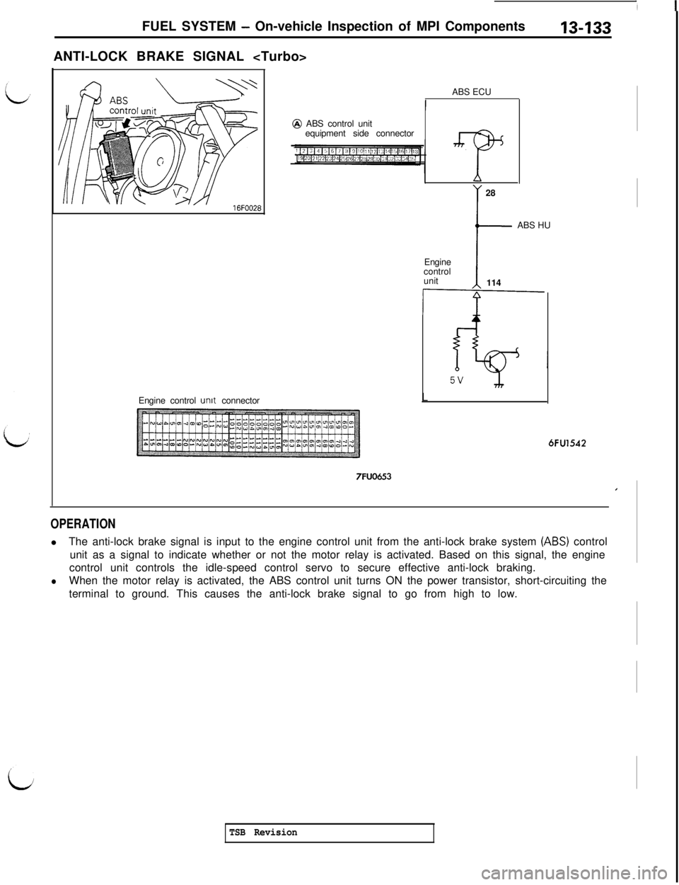
ANTI-LOCK BRAKE SIGNAL
Engine control
unit connectorABS ECU@ ABS control unit
equipment side connector
A28
tABS HU
Engine
control
unit
114
/L6FU1542
7FUO653,
OPERATIONlThe anti-lock brake signal is input to the engine control unit from the anti-lock brake system
(ABS) control
unit as a signal to indicate whether or not the motor relay is activated. Based on this signal, the engine
control unit controls the idle-speed control servo to secure effective anti-lock braking.
lWhen the motor relay is activated, the ABS control unit turns ON the power transistor, short-circuiting the
terminal to ground. This causes the anti-lock brake signal to go from high to low.
TSB Revision
Page 240 of 1146
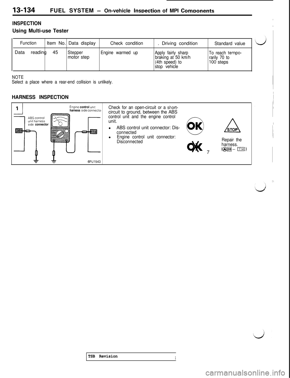
13-134FUEL SYSTEM - On-vehicle InsDection of MPI ComDonents
INSPECTIONUsing Multi-use Tester
FunctionItem No. Data displayCheck condition. Driving conditionStandard valueData reading 45
Stepper
Engine warmed up
Apply fairly sharp
To reach tempo-motor stepbraking at 50 km/h
rarily 70 to
(4th speed) to100 stepsstop vehicle
NOTESelect a place where a rear-end collision is unlikely.
HARNESS INSPECTION
side connector
Engine control umtharness side connecm
6FU1543
Check for an open-circuit or a short-circuit to ground, between the ABScontrol unit and the engine controlunit.l
ABS control unit connector: Dis-connectedlEngine control unit connector:
Disconnected7Repair the
harness.
(@m-ml)
I
I
I
I
IiI
I
~,
I\
TSB Revision1
Trending: roof rack, service reset, oil, key battery, washer fluid, open gas tank, brake fluid
