MITSUBISHI 3000GT 1991 Service Manual
Manufacturer: MITSUBISHI, Model Year: 1991, Model line: 3000GT, Model: MITSUBISHI 3000GT 1991Pages: 1146, PDF Size: 76.68 MB
Page 241 of 1146
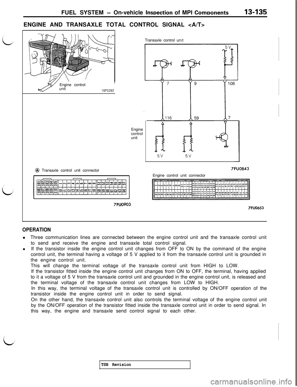
Page 242 of 1146
13-136FUEL SYSTEM - On-vehicle Inspection of MPI Components
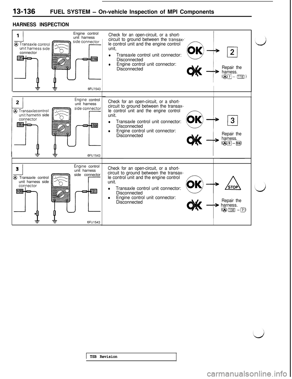
HARNESS INSPECTION
’ IEngine control
unit harness
&;;;;;g;;gconnector
.j/ \%: c.
T
Check for an open-circuit, or a short-circuit to ground between the transax-’le control unit and the engine controlunit,
lTransaxle control unit connector:
Disconnected
lEngine control unit connector:
Disconnected
c----JOK
Repair the
harness.
C@pJ- 11161)
*6FU1543Engine control
unit harness
control
?ss side
6FU1543
-I3@ Transaxle control
unit harness sideEngine control
unit harness
side connector
6FU1543
Check for an open-circuit, or a short-circuit to ground between the transax-le control unit and the engine control-unit.
lTransaxle control unit connector:
Disconnected
lEngine control unit connector:
DisconnectedRepair the
harness.
@pJ-gj,
Check for an open-circuit, or a short-circuit to ground between the transax-
le control unit and the engine control
unit.
lTransaxle control unit connector:
Disconnected
lEngine control unit connector:
DisconnectedRepair the-+ harness.
@ml -FJ)
1 TSB Revision
Page 243 of 1146
FUEL SYSTEM - Orwehicle lnwection of MPI Components.13-137Fuel gauge cover
03FOOO4
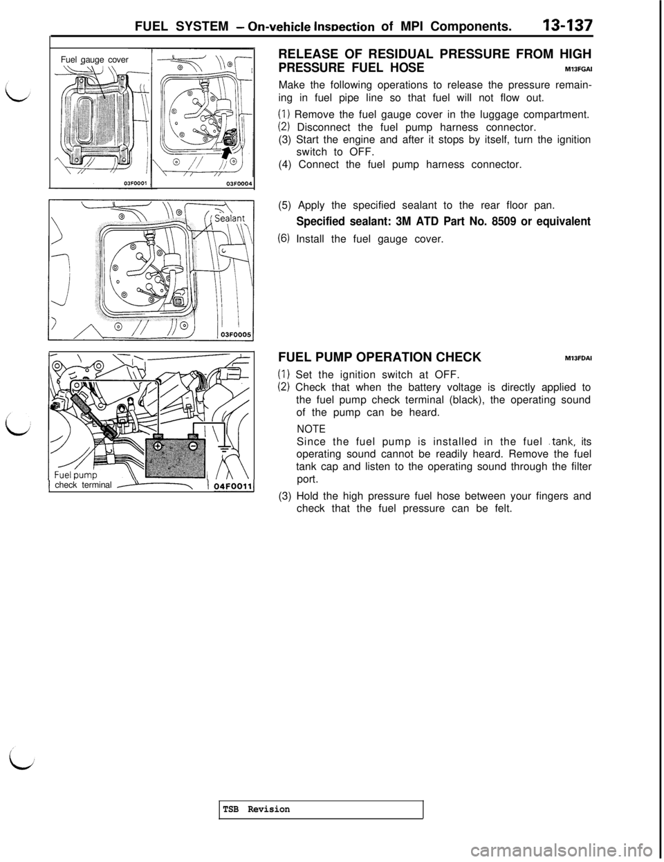
j check terminal ----T( 04~oo1,/RELEASE OF RESIDUAL PRESSURE FROM HIGH
PRESSURE FUEL HOSEM13FGAIMake the following operations to release the pressure remain-
ing in fuel pipe line so that fuel will not flow out.
(I) Remove the fuel gauge cover in the luggage compartment.
(2) Disconnect the fuel pump harness connector.
(3) Start the engine and after it stops by itself, turn the ignition
switch to OFF.
(4) Connect the fuel pump harness connector.
(5) Apply the specified sealant to the rear floor pan.
Specified sealant: 3M ATD Part No. 8509 or equivalent
(6) Install the fuel gauge cover.
FUEL PUMP OPERATION CHECK
M13FDAI
(1) Set the ignition switch at OFF.
(2) Check that when the battery voltage is directly applied to
the fuel pump check terminal (black), the operating sound
of the pump can be heard.
NOTESince the fuel pump is installed in the fuel
.tank, its
operating sound cannot be readily heard. Remove the fuel
tank cap and listen to the operating sound through the filter
port.
(3) Hold the high pressure fuel hose between your fingers and
check that the fuel pressure can be felt.
TSB Revision
Page 244 of 1146
13438FUEL SYSTEM - On-vehicle Inspection of MPI ComponentsI/
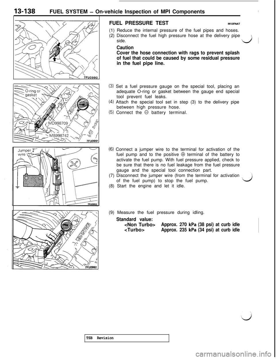
FUEL PRESSURE TESTMlJFNAT(1) Reduce the internal pressure of the fuel pipes and hoses.
(2) Disconnect the fuel high pressure hose at the delivery pipe
side.
dl
Caution
Cover the hose connection with rags to prevent splash
of fuel that could be caused by some residual pressurein the fuel pipe line.
(3) Set a fuel pressure gauge on the special tool, placing an
adequate O-ring or gasket between the gauge end special
tool prevent fuel leaks.
(4) Attach the special tool set in step (3) to the delivery pipe
between high pressure hose.
(5) Connect the 0 battery terminal.
(6) Connect a jumper wire to the terminal for activation of the
fuel pump and to the positive
0 terminal of the battery to
activate the fuel pump. With fuel pressure applied, check to
be sure that there is no fuel leakage from the fuel pressure
gauge and the special tool connection part.
(7) Disconnect the jumper wire (from the terminal for activation
’of the fuel pump) to stop the fuel pump.
(8) Start the engine and let it idle.
d(9) Measure the fuel pressure during idling.
Standard value:
Approx. 270 kPa (38 psi) at curb idle
Approx. 235 kPa (34 psi) at curb idle
TSB Revision
Page 245 of 1146
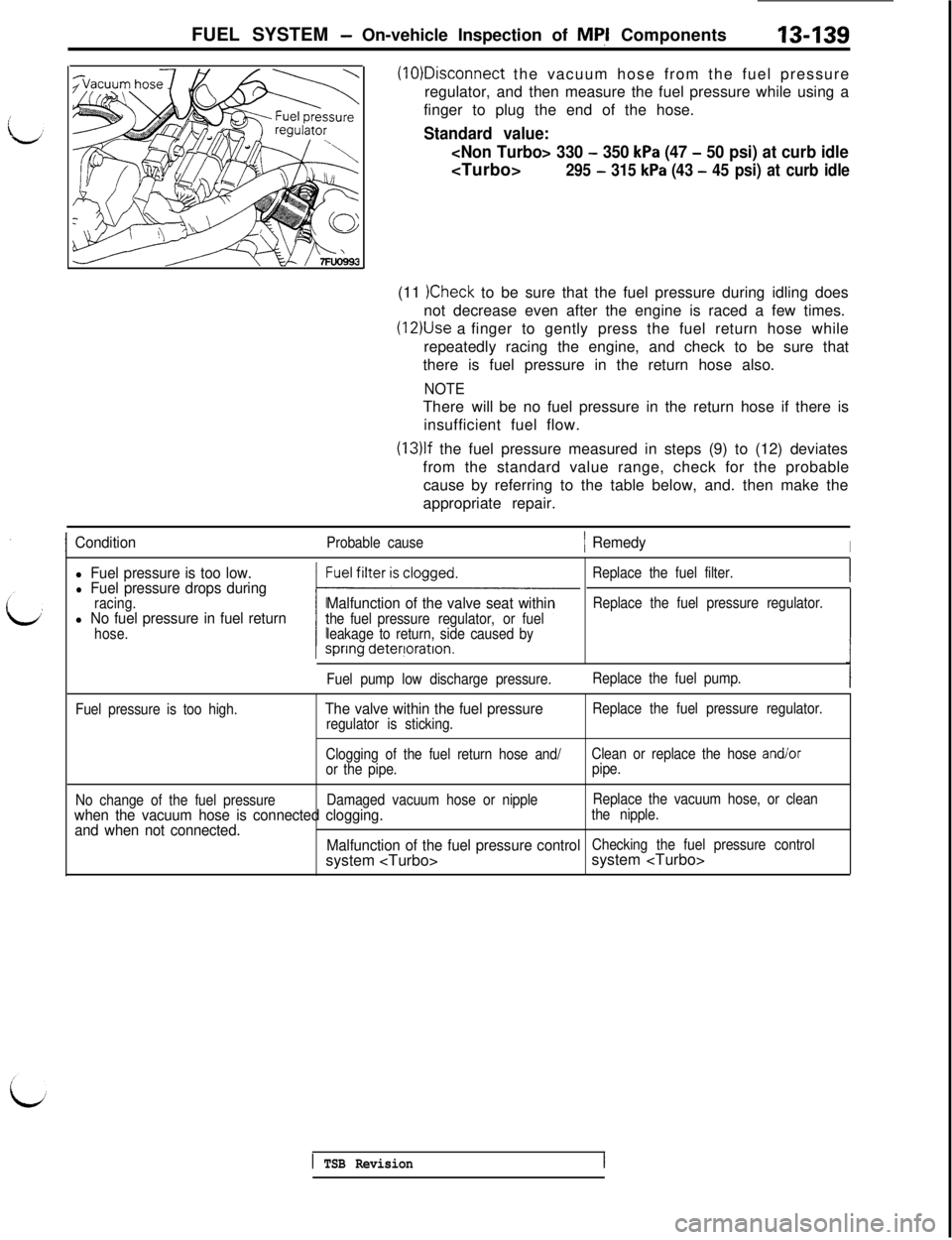
FUEL SYSTEM - On-vehicle Inspection of Mql Components13439(10)Disconnect the vacuum hose from the fuel pressure
regulator, and then measure the fuel pressure while using a
finger to plug the end of the hose.
Standard value:
- 350 kPa (47 - 50 psi) at curb idle
295 - 315 kPa (43 - 45 psi) at curb idle(11
)Check to be sure that the fuel pressure during idling does
not decrease even after the engine is raced a few times.
(12)Use a finger to gently press the fuel return hose while
repeatedly racing the engine, and check to be sure that
there is fuel pressure in the return hose also.
NOTEThere will be no fuel pressure in the return hose if there is
insufficient fuel flow.
(13)lf the fuel pressure measured in steps (9) to (12) deviates
from the standard value range, check for the probable
cause by referring to the table below, and. then make the
appropriate repair.
IConditionProbable cause1 RemedyI
l Fuel pressure is too low.l Fuel pressure drops duringracing.l No fuel pressure in fuel returnhose.
Malfunction of the valve seat withinthe fuel pressure regulator, or fuel
leakage to return, side caused byReplace the fuel filter.
Replace the fuel pressure regulator.
Fuel pump low discharge pressure.Replace the fuel pump.
Fuel pressure is too high.
The valve within the fuel pressureregulator is sticking.Replace the fuel pressure regulator.
Clogging of the fuel return hose and/Clean or replace the hose
and/oror the pipe.pipe.
No change of the fuel pressureDamaged vacuum hose or nippleReplace the vacuum hose, or clean
when the vacuum hose is connected clogging.the nipple.
and when not connected.
Malfunction of the fuel pressure controlChecking the fuel pressure controlsystem
1 TSB Revision
Page 246 of 1146
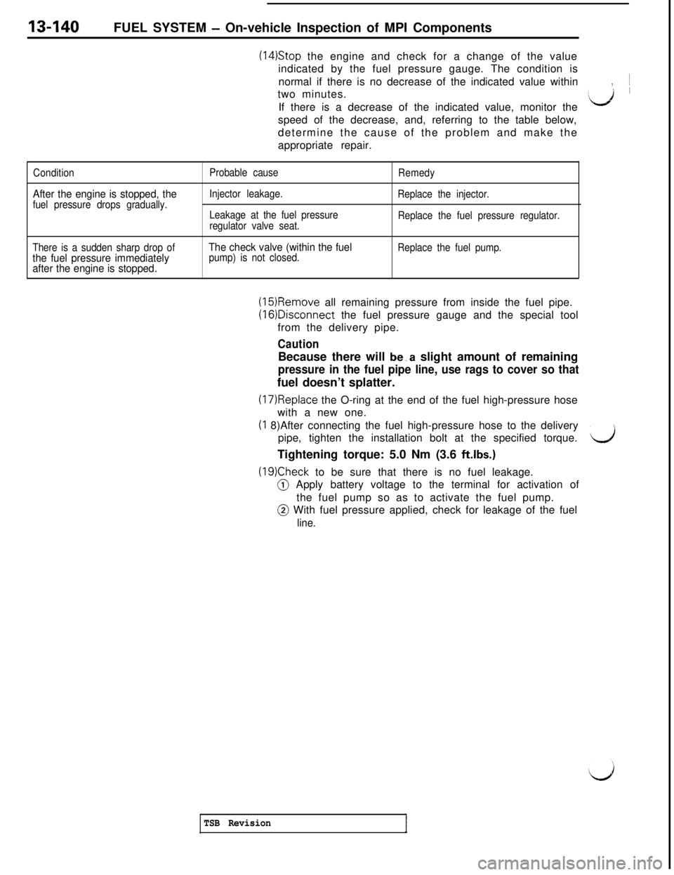
13-140FUEL SYSTEM - On-vehicle Inspection of MPI Components
(14)Stop the engine and check for a change of the value
indicated by the fuel pressure gauge. The condition is
normal if there is no decrease of the indicated value within~
two minutes.
,If there is a decrease of the indicated value, monitor the
:d ’speed of the decrease, and, referring to the table below,
determine the cause of the problem and make the
appropriate repair.
Condition
After the engine is stopped, thefuel pressure drops gradually.Probable cause
Injector leakage.
Leakage at the fuel pressure
regulator valve seat.Remedy
Replace the injector.
Replace the fuel pressure regulator.
There is a sudden sharp drop of
the fuel pressure immediately
after the engine is stopped.The check valve (within the fuelpump) is not closed.Replace the fuel pump.
(15)Remove all remaining pressure from inside the fuel pipe.(16)Disconnect the fuel pressure gauge and the special tool
from the delivery pipe.
CautionBecause there will be.a slight amount of remaining
pressure in the fuel pipe line, use rags to cover so thatfuel doesn’t splatter.
(17)Replace the O-ring at the end of the fuel high-pressure hose
with a new one.(I 8)After connecting the fuel high-pressure hose to the delivery
pipe, tighten the installation bolt at the specified torque.
dTightening torque: 5.0 Nm (3.6 ftlbs.)
(19)Check to be sure that there is no fuel leakage.@ Apply battery voltage to the terminal for activation of
the fuel pump so as to activate the fuel pump.@ With fuel pressure applied, check for leakage of the fuel
line.
TSB Revision
Page 247 of 1146
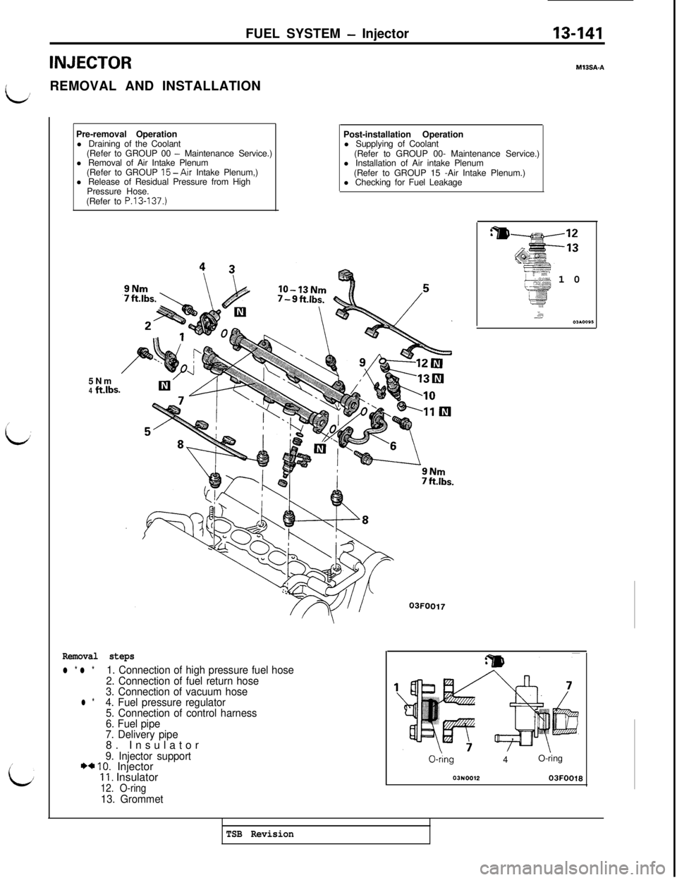
FUEL SYSTEM - Injector13-141
INJECTOR
LREMOVAL AND INSTALLATION
!
MlBSA-A
/
LPre-removal Operation
l Draining of the Coolant
(Refer to GROUP 00
- Maintenance Service.)
l Removal of Air Intake Plenum
(Refer to GROUP
15-Air Intake Plenum,)
l Release of Residual Pressure from High
Pressure Hose.
(Refer to P.13-137.)
5Nm
4
WbsPost-installation Operation
l Supplying of Coolant
(Refer to GROUP 00- Maintenance Service.)
l Installation of Air intake Plenum
(Refer to GROUP 15 -Air Intake Plenum.)
l Checking for Fuel Leakage
03FOO17
Removal steps
l * l *1. Connection of high pressure fuel hose
2. Connection of fuel return hose
3. Connection of vacuum hose
l *4. Fuel pressure regulator
5. Connection of control harness
6. Fuel pipe
7. Delivery pipe8. Insulator
9. Injector support*+ IO. Injector11. Insulator12. O-ring13. Grommet
:m
*:”
-aI : %~’.1X.-10p$
y&,*,,A200A0005
0-hng4O-ring
03N001203FOO18
TSB Revision
Page 248 of 1146
13-142FUEL SYSTEM - Injector
SERVICE POINT OF REMOVAL
MlBSSAI1. DISCONNECTION OF HIGH PRESSURE FUEL HOSE
Bleed the residual pressure within the fuel pipe line so as to
LA;prevent the flow of fuel.
Caution
Cover the hose connection with rags to prevent splash
of fuel that could be caused by some residual pressurein the fuel pipe line.
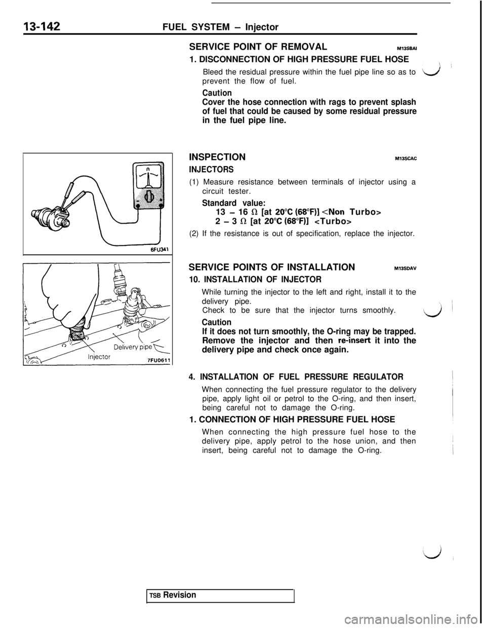
INSPECTION
INJECTORS
M13SCAC(1) Measure resistance between terminals of injector using a
circuit tester.
Standard value:13
- 16 R [at 20°C (68”F)]
2
- 3 LR [at 20°C (68”F)l
(2) If the resistance is out of specification, replace the injector.
SERVICE POINTS OF INSTALLATION
MlBSDAV
10. INSTALLATION OF INJECTORWhile turning the injector to the left and right, install it to the
delivery pipe.
Check to be sure that the injector turns smoothly.
LCaution
If it does not turn smoothly, the O-ring may be trapped.Remove the injector and then
m-insert it into the
delivery pipe and check once again.
4. INSTALLATION OF FUEL PRESSURE REGULATORWhen connecting the fuel pressure regulator to the delivery
pipe, apply light oil or petrol to the O-ring, and then insert,
being careful not to damage the O-ring.
1. CONNECTION OF HIGH PRESSURE FUEL HOSE
When connecting the high pressure fuel hose to the
delivery pipe, apply petrol to the hose union, and then
insert, being careful not to damage the O-ring.
TSB Revision
Page 249 of 1146
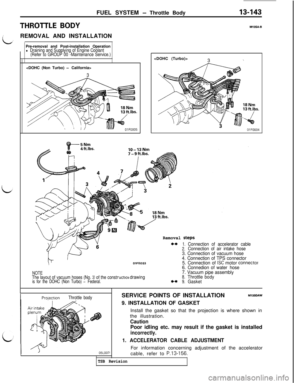
FUEL SYSTEM - Throttle Body13-143Pre-removal and Post-installation Operation
l Draining and Supplying of Engine Coolant
(Refer to GROUP 00 -Maintenance Service.)
3
THROTTLE BODY
I
idREMOVAL AND INSTALLATION
MIOSA-0
3\
OlFOOO4
NOTEThe layout of vacuum hoses (No. 3) of the constris for the DOHC (Non Turbo) - Federal.
OlFOO53
I drawing
Removal sl
+*1.Connection of accelerator cable2.Connection of air intake hose3. Connection of vacuum hose
4. Connection of TPS connector
5. Connection of
ISC motor connec6. Connedion of water hose
7. Vacuum pipe assembly
8.ThrottlebodyI)*9.Gasket
:eps
:tor
PrelectionThrottle bodySERVICE POINTS OF INSTALLATIONMlBSDAW9. INSTALLATION OF GASKET
Install the gasket so that the projection is where shown in
the illustration.
CautionPoor idling etc. may result if the gasket is installed
incorrectly.
1. ACCELERATOR CABLE ADJUSTMENTFor information concerning adjustment of the accelerator
cable, refer to
P.13-156.
TSB Revision
Page 250 of 1146
13-144FUEL SYSTEM - Throttle- Body
DISASSEMBLY AND REASSEMBLY
2.0
Nni1.4ft.lbs.
/
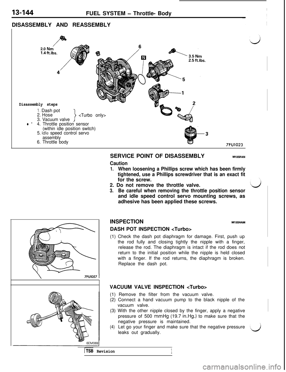
Disassembly steps
1. Dash pot2. Hose
3. Vacuum valve
>
l *4. Throttle position sensor
(within idle position switch)
5.
Idle speed control servo
assembly
6. Throttle body
7FU1023
\7FU1057 1SERVICE POINT OF DISASSEMBLY
MlBSFAN
Caution
1.When loosening a Phillips screw which has been firmly
tightened, use a Phillips screwdriver that is an exact fitfor the screw.
2. Do not remove the throttle valve.
3.Be careful when removing the throttle position sensorand idle speed control servo mounting screws, as
adhesive has been applied these screws.
INSPECTION
Ml3SHAt.lDASH POT INSPECTION
(1) Check the dash pot diaphragm for damage. First, push up
the rod fully and closing tightly the nipple with a finger,
release the rod. The diaphragm is intact if the rod does not
return to the initial position while the nipple is held closed
with a finger. If the rod returns, the diaphragm is broken.
Replace the dash pot.
VACUUM VALVE INSPECTION
(1) Remove the filter from the vacuum valve.
(2) Connect a hand vacuum pump to the black nipple of the
vacuum valve.
(3) With the other nipple closed by the finger, apply a negative
pressure of 500 mmHg (19.7 in.Hg.) to make sure that the
negative pressure is maintained.
(4)Let go your finger and make sure that the negative pressure
leaks out gradually.
hSB Revision1