MITSUBISHI 3000GT 1991 Service Manual
Manufacturer: MITSUBISHI, Model Year: 1991, Model line: 3000GT, Model: MITSUBISHI 3000GT 1991Pages: 1146, PDF Size: 76.68 MB
Page 251 of 1146
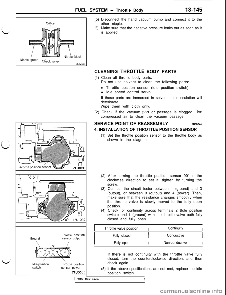
FUEL SYSTEM - Throttle Body13-145Orifice
Nipple (green)3EM05iGroundThrottle
positlonsensor output
Idle-position
switchTh>ottle position
sensor power7FUO535(5) Disconnect the hand vacuum pump and connect it to the
other nipple.
(6)Make sure that the negative pressure leaks out as soon as it
is applied.
CLEANING THROTTLE BODY PARTS
(1) Clean all throttle body parts.
Do not use solvent to clean the following parts:
l Throttle position sensor (Idle position switch)
l Idle speed control servo
If these parts are immersed in solvent, their insulation will
deteriorate.
Wipe them with cloth only.
(2) Check if the vacuum
pot-t or passage is clogged. usecompressed air to clean the vacuum passage.
SERVICE POINT OF REASSEMBLY
M13SGAN4. INSTALLATION OF THROTTLE POSITION SENSOR
(1) Set the throttle position sensor to the throttle body as
shown in the diagram.
(2) After turning the throttle position sensor 90” in the
clockwise direction to set it, tighten by turning the
screw.
(3) Connect the circuit tester between 1 (ground) and 3
(output), or between 3 (output) and 4 (power). Then,
make sure that the resistance changes smoothly when
the throttle valve is slowly moved to the fully open
position.
(4) Check for continuity across terminals 2 (Idle position
switch) and 1 (ground) with the throttle valve both fully
closed and fully open.
IThrottle valve positionIContinuityI
Fully closedConductive
Fully openINon-conductiveIIf there is not continuity with the throttle valve fully
closed, turn the counterclockwise direction, and then
check again.
(5) If the above specifications are not met, replace the idle
position switch.
1 TSB RevisionI
Page 252 of 1146
13-146FUEL SYSTEM - Fuel Tank
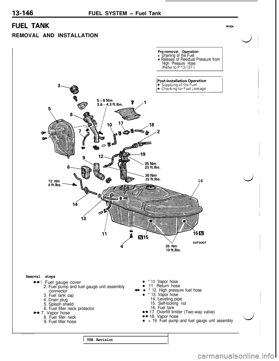
FUEL TANKREMOVAL AND INSTALLATIONM13GA- -12 Nm
8 ft.lbs. WPre-removal Operation
l Draining of the Fuel0 Release of Residual Pressure fromHigh Pressure Hose.(Referto P.13-137.)
5-6Nm25 ft.lbs.
b22 ftlbs.16
V26 Nm
19 ft.lbs.
03FOOO7
Removal steps
** I. Fuel gauge cover2. Fuel pump and fuel gauge unit assembly
connector
3. Fuel tank cap4. Drain plug
5. Splash shield
6. Fuel filler neck protector
** 7. Vapor hose8. Fuel filler neck9. Fuel filler hose
l * IO. Vapor hosel 11. Return hose+* l * 12. High pressure fuel hosel * 13. Vapor hose14. Leveling pipe15. Self-locking nut
16. Fuel tank++
17. Overfill limiter (Two-way valve)I)+ 18. Vapor hosel + 19. Fuel pump and fuel gauge unit assembly
;d
I
1 TSB Revision
Page 253 of 1146
FUEL SYSTEM - Fuel Tank13-147
Rubber hose
ngn
03FOOl
9
OSFOOB
05FOO7SERVICE POINT OF REMOVAL
MlBGBAK
12. DISCONNECTION OF HIGH PRESSURE FUEL HOSEDisconnect the hose from body main pipe first and then
from fuel pump.
Caution
Cover the hose connection with rags to prevent splash
of fuel that could be caused by some residual pressurein the fuel pipe line.
INSPECTION
MlBGCAMl Check the hoses and the pipes for crack or damage.
l Check the fuel tank cap for malfunction.
l Check the fuel tank for deformation, corrosion or crack.
l Check the fuel tank for dust or foreign material.
NOTEIf the inside of the fuel tank is to be cleaned, use any one of
the following:
(1) Kerosene
(2) Trichloroethylene
(3) A neutral emulsion type detergent
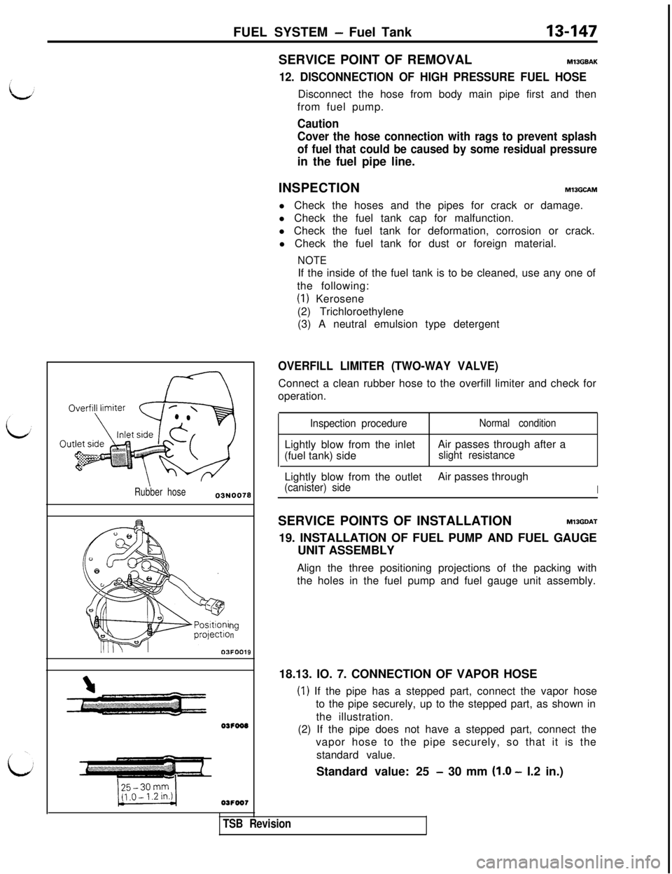
OVERFILL LIMITER (TWO-WAY VALVE)Connect a clean rubber hose to the overfill limiter and check for
operation.
Inspection procedureLightly blow from the inlet
(fuel tank) sideNormal conditionAir passes through after a
slight resistanceLightly blow from the outletAir passes through
(canister) sideISERVICE POINTS OF INSTALLATION
MlSGDAT19. INSTALLATION OF FUEL PUMP AND FUEL GAUGE
UNIT ASSEMBLY
Align the three positioning projections of the packing with
the holes in the fuel pump and fuel gauge unit assembly.
TSB Revision18.13. IO. 7. CONNECTION OF VAPOR HOSE
(1) If the pipe has a stepped part, connect the vapor hose
to the pipe securely, up to the stepped part, as shown in
the illustration.
(2) If the pipe does not have a stepped part, connect the
vapor hose to the pipe securely, so that it is the
standard value.
Standard value: 25
- 30 mm (1.0 - I.2 in.)
Page 254 of 1146
13-148FUEL SYSTEM - Fuel Tank
Canistide
Do3041Flare nut
Se&e side
0310430%
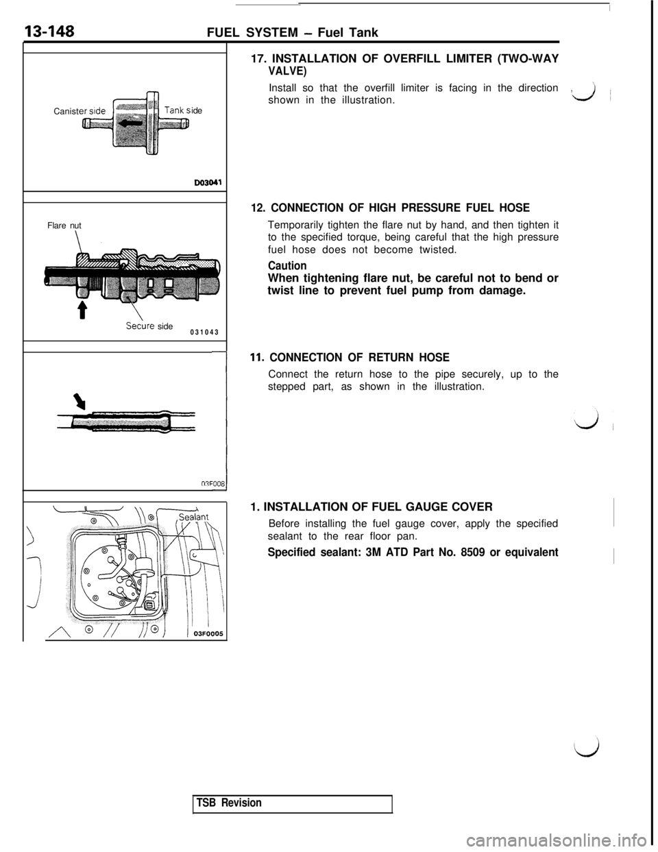
e:00817. INSTALLATION OF OVERFILL LIMITER (TWO-WAY
VALVE)Install so that the overfill limiter is facing in the direction
’,~
shown in the illustration.L.&l
12. CONNECTION OF HIGH PRESSURE FUEL HOSETemporarily tighten the flare nut by hand, and then tighten it
to the specified torque, being careful that the high pressure
fuel hose does not become twisted.
CautionWhen tightening flare nut, be careful not to bend or
twist line to prevent fuel pump from damage.
11. CONNECTION OF RETURN HOSEConnect the return hose to the pipe securely, up to the
stepped part, as shown in the illustration.
1. INSTALLATION OF FUEL GAUGE COVER
Before installing the fuel gauge cover, apply the specified
sealant to the rear floor pan.
Specified sealant: 3M ATD Part No. 8509 or equivalent
TSB Revision
Page 255 of 1146
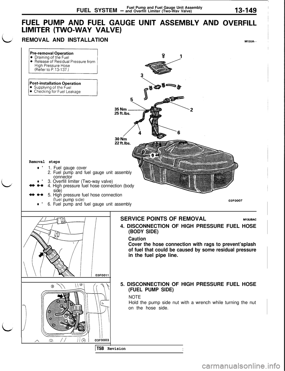
FUEL SYSTEMFuel Pump and Fuel Gauge Unit Assembly- and Overfill Limiter (Two-Wav Valve)13449
FUEL PUMP AND FUEL GAUGE UNIT ASSEMBLY ANDOVERFILL
LIMITER (TWO-WAY VALVE)
1:REMOVAL AND INSTALLATIONMIBUA- -
L
Removal steps
l *1. Fuel gauge cover
2. Fuel pump and fuel gauge unit assembly
connectorl *3. Overfill limiter (Two-way valve)*I) I)+4. High pressure fuel hose connection (body
side)a* I)*5. High pressure fuel hose connection.
(tuel pump side)03FOOO7l *6. Fuel pump and fuel gauge unit assembly
~03FOOll
I
LJISERVICE POINTS OF REMOVAL
MlSUBAC4. DISCONNECTION OF HIGH PRESSURE FUEL HOSE
(BODY SIDE)
Caution
Cover the hose connection with rags to prevent’splash
of fuel that could be caused by some residual pressurein the fuel pipe line.
5. DISCONNECTION OF HIGH PRESSURE FUEL HOSE
(FUEL PUMP SIDE)
NOTEHold the pump side nut with a wrench while turning the nut
on the hose side.
[TSB RevisionI
Page 256 of 1146
13-150FUEL SYSTEMFuel Pump and Fuel Gauge Unit Assembly- and Overfill Limiter (Two-Way Valve)
Rubber hose
9Flare nut
Secure side
03Yo43Camst
ide
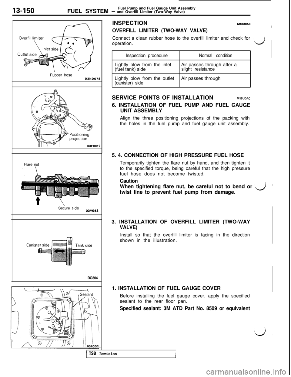
DO304INSPECTION
MlBUCAB
OVERFILL LIMITER (TWO-WAY VALVE)~
Connect a clean rubber hose to the overfill limiter and check for
operation.
‘d
Inspection procedureNormal conditionLightly blow from the inlet
(fuel tank) sideAir passes through after a
slight resistanceLightly blow from the outlet
(canister) sideAir passes through
SERVICE POINTS OF INSTALLATION
M13UDAC6. INSTALLATION OF FUEL PUMP AND FUEL GAUGE
UNIT ASSEMBLY
Align the three positioning projections of the packing with
the holes in the fuel pump and fuel gauge unit assembly.
5. 4. CONNECTION OF HIGH PRESSURE FUEL HOSE
Temporarily tighten the flare nut by hand, and then tighten it
to the specified torque, being careful that the high pressure
fuel hose does not become twisted.
CautionWhen tightening flare nut, be careful not to bend or
[J’twist line to prevent fuel pump from damage.\3. INSTALLATION OF OVERFILL LIMITER (TWO-WAY
VALVE)Install so that the overfill limiter is facing in the direction
shown in the illustration.
1. INSTALLATION OF FUEL GAUGE COVER
Before installing the fuel gauge cover, apply the specified
sealant to the rear floor pan.
Specified sealant: 3M ATD Part No. 8509 or equivalent
1 TSB RevisionIII
Page 257 of 1146
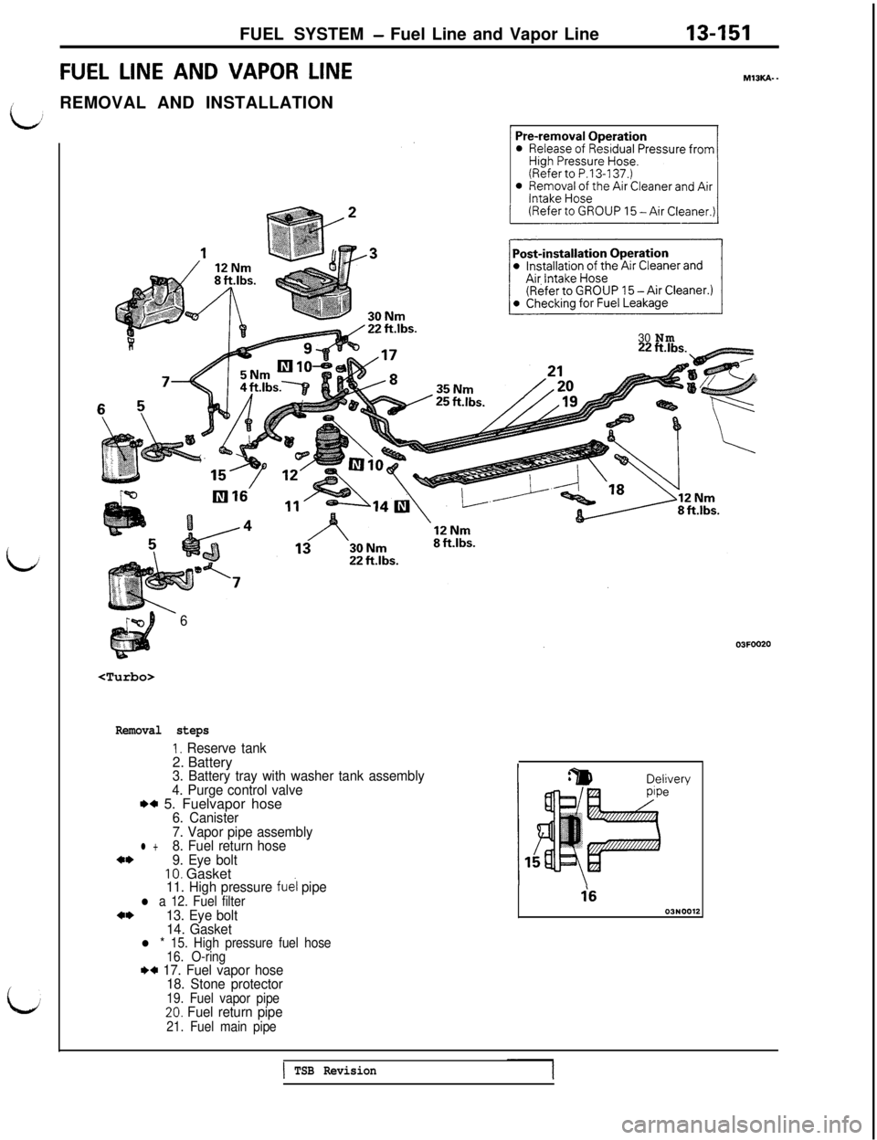
FUEL SYSTEM- Fuel Line and Vapor Line13451FUEL
LINE AND VAPOR LINEMlBKA-~
iREMOVAL AND INSTALLATION
i30 Nm
6
Removal steps
1, Reserve tank2. Battery
3. Battery tray with washer tank assembly
4. Purge control valve
M 5. Fuelvapor hose6. Canister
7. Vapor pipe assembly
l +8. Fuel return hosea*9. Eye bolt10. Gasket11. High pressure fuel pipel a 12. Fuel filter*I,13. Eye bolt
14. Gasket
l * 15. High pressure fuel hose
16. O-ring
w 17. Fuel vapor hose
18. Stone protector
19. Fuel vapor pipe20. Fuel return pipe
21. Fuel main pipe
Deli\rerye
i603N0012
1 TSB Revision
Page 258 of 1146
13-152FUEL SYSTEM- Fuel Line and Vapor Line
03FOO3
05FOO735 Nm7r; ft
Ihr-k” ._..I_.
@dFlare nut,xSERVICE POINTS OF REMOVAL
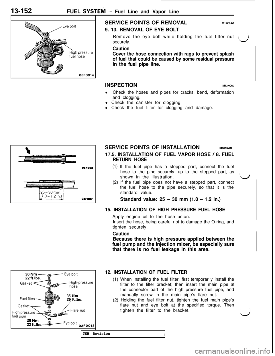
MlBKBAQ9. 13. REMOVAL OF EYE BOLT
Remove the eye bolt while holding the fuel filter nut
\securely.
Caution
Cover the hose connection with rags to prevent splash
of fuel that could be caused by some residual pressurein the fuel pipe line.
INSPECTION
MIBKCAJ
lCheck the hoses and pipes for cracks, bend, deformation
and clogging.
l Check the canister for clogging.
l Check the fuel filter for clogging and damage.
SERVICE POINTS OF INSTALLATION
MlSKDAU17.5. INSTALLATION OF FUEL VAPOR HOSE
/ 8. FUEL
RETURN HOSE
(1) If the fuel pipe has a stepped part, connect the fuel
hose to the pipe securely, up to the stepped part, as
shown in the illustration.
Iti(2) If the fuel pipe does not have a stepped part, connect
the fuel hose to the pipe securely, so that it is the
standard value.
Standard value: 25
- 30 mm (1.0 - 1.2 in.)
15. INSTALLATION OF HIGH PRESSURE FUEL HOSEApply engine oil to the hose union.
Insert the hose, being careful not to damage the O-ring, and
tighten securely.
CautionBecause there is high pressure applied between the
fuel pump and the injection mixer, be especially sure
that there is no fuel leakage in this area.
12. INSTALLATION OF FUEL FILTER(1) When installing the fuel filter, first temporarily install the
filter to the filter bracket; then insert the main pipe at
the connector part of the high pressure fuel pipe, and
manually screw in the main pipe’s flare nut.
(2) Holding the fuel filter nut, tighten the fuel main pipe’s
flare nut and eye bolt at the specified torque. Then
tighten the filter to the bracket.
TSB Revision1
‘d
Page 259 of 1146
FUEL SYSTEM - Fuel Filter13453
FUEL FILTERM13VA-.
/REMOVAL AND INSTALLATION
i&J
L
/Il Removal of Residual Pressure from
Post-installation Operation
l Checking for Fuel Leakage
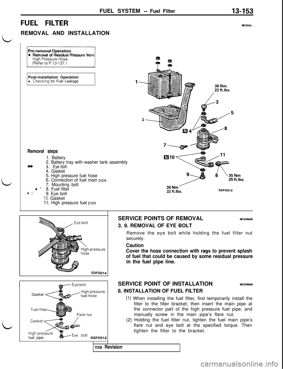
Removal steps
1. Battery
2. Battery tray with washer tank assembly
3. Eye bolt4. Gasket
5. High pressure fuel hose
6. Connection of fuel main
pipe7. Mounting boltl *8. Fuel filterl *9. Eye bolt10. Gasket11. High pressure fuel pipe
l---
222 ft.lbs.03FOO12
Gasket
fuel pipe
&----Eye bo’t 03FOO13SERVICE POINTS OF REMOVAL
MlSVBAB3. 9. REMOVAL OF EYE BOLT
Remove the eye bolt while holding the fuel filter nut
securely.
Caution
Cover the hose connection with
rags to prevent splash
of fuel that could be caused by some residual pressurein the fuel pipe line.
SERVICE POINT OF INSTALLATION
M13VBAB8. INSTALLATION OF FUEL FILTER
(1) When installing the fuel filter, first temporarily install the
filter to the filter bracket; then insert the main pipe at
the connector part of the high pressure fuel pipe, and
manually screw in the main pipe’s flare nut.
(2) Holding the fuel filter nut, tighten the fuel main pipe’s
flare nut and eye bolt at the specified torque. Then
tighten the filter to the bracket.
TSB Revision
Page 260 of 1146
13-154FUEL SYSTEM - Detonation Sensor
DETONATION SENSORREMOVAL AND INSTALLATION
Pre-removal and Post-installation Operation
l Release and Installation of the Air Intake Plenum
(Refer to GROUP
15-Air Intake Plenum.)
l Removal and Installation of the Intake Manifold
(Refer to GROUP 15
- Intake Manifold.)
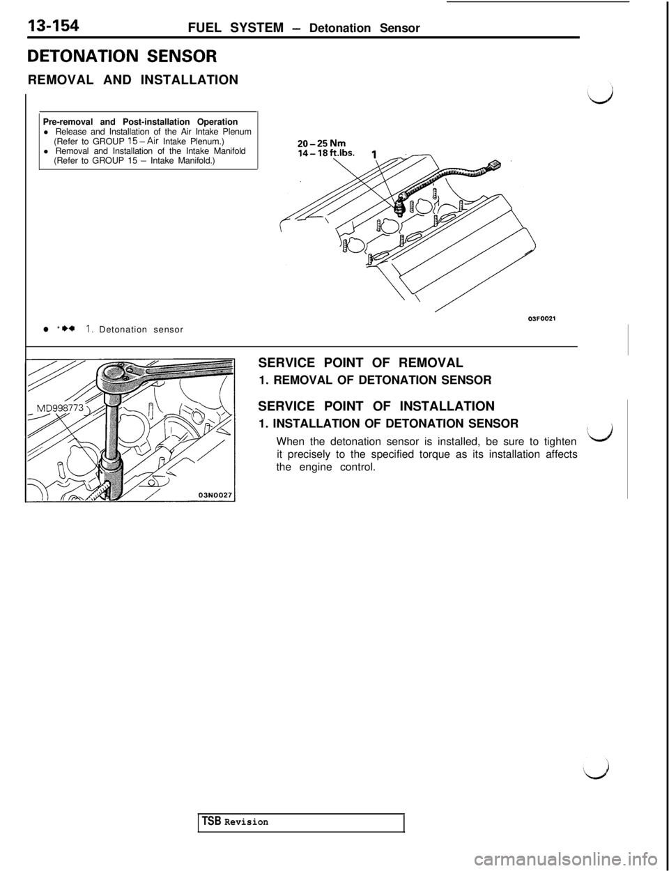
l * +*I. Detonation sensor
20-25NmSERVICE POINT OF REMOVAL
1. REMOVAL OF DETONATION SENSOR
SERVICE POINT OF INSTALLATION
1. INSTALLATION OF DETONATION SENSOR
When the detonation sensor is installed, be sure to tighten
Idit precisely to the specified torque as its installation affects
the engine control.
TSB Revision