MITSUBISHI 3000GT 1991 Service Manual
Manufacturer: MITSUBISHI, Model Year: 1991, Model line: 3000GT, Model: MITSUBISHI 3000GT 1991Pages: 1146, PDF Size: 76.68 MB
Page 361 of 1146
CLUTCH - Specifications / Troubleshooting21-3
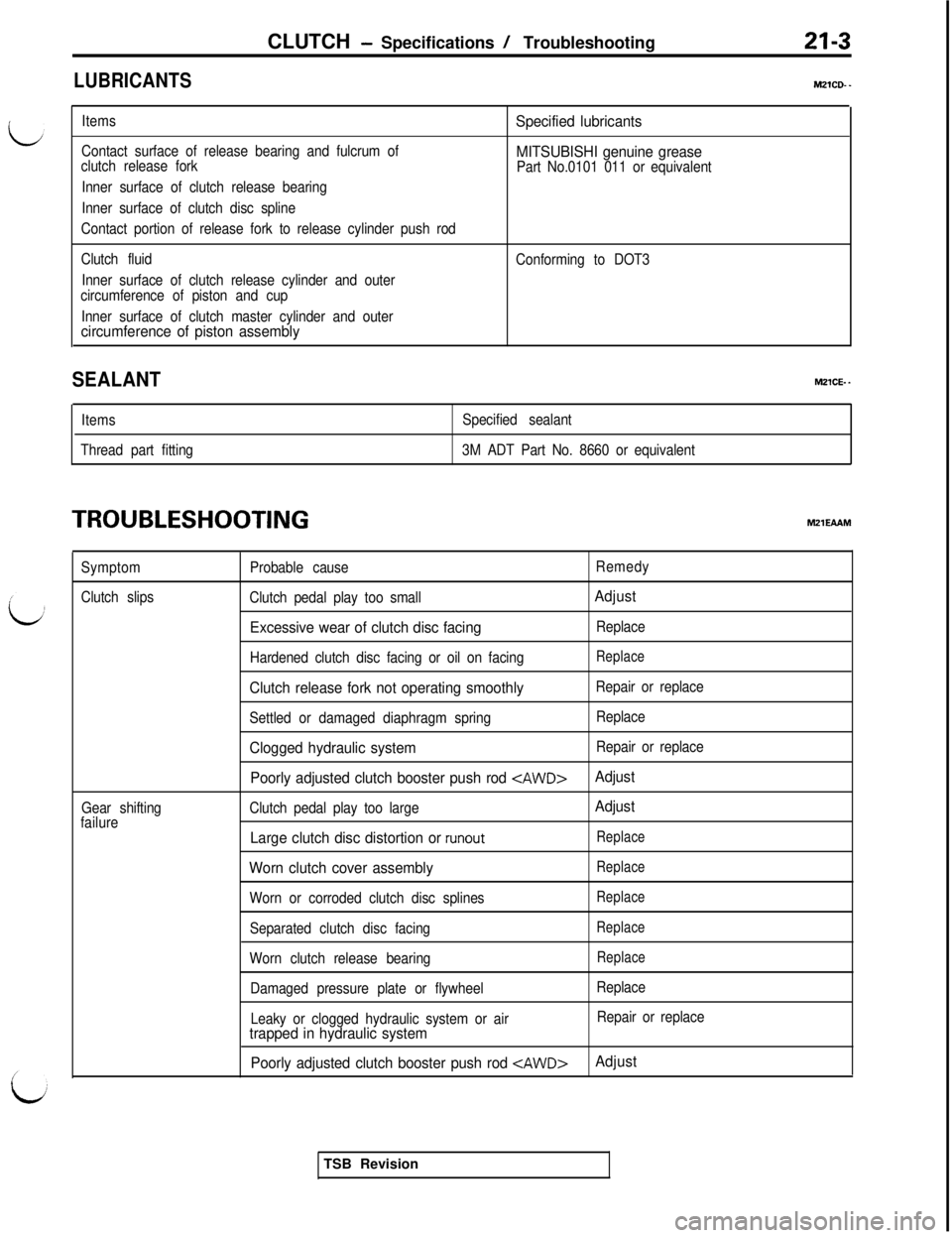
LUBRICANTS
Items
Contact surface of release bearing and fulcrum of
clutch release forkSpecified lubricants
MITSUBISHI genuine grease
Part No.0101 011 or equivalent
Inner surface of clutch release bearing
Inner surface of clutch disc spline
Contact portion of release fork to release cylinder push rod
Clutch fluid
Inner surface of clutch release cylinder and outer
circumference of piston and cup
Inner surface of clutch master cylinder and outer
circumference of piston assembly
Conforming to DOT3
SEALANTM21CE. -
Items
Thread part fittingSpecified sealant
3M ADT Part No. 8660 or equivalent
TROUBLESHOOTINGtvl21EAAM
Symptom
Clutch slips
Gear shifting
failureProbable cause
Clutch pedal play too small
Excessive wear of clutch disc facing
Hardened clutch disc facing or oil on facing
Clutch release fork not operating smoothly
Settled or damaged diaphragm spring
Clogged hydraulic system
Poorly adjusted clutch booster push rod
Clutch pedal play too large
Large clutch disc distortion or runout
Worn clutch cover assembly
Worn or corroded clutch disc splines
Separated clutch disc facing
Worn clutch release bearing
Damaged pressure plate or flywheel
Leaky or clogged hydraulic system or air
trapped in hydraulic system
Poorly adjusted clutch booster push rod
Remedy
Adjust
Replace
Replace
Repair or replace
Replace
Repair or replace
Adjust
Adjust
Replace
Replace
Replace
Replace
Replace
Replace
Repair or replace
AdjustTSB Revision
Page 362 of 1146
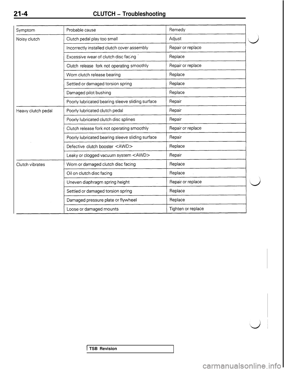
21-4CLUTCH - Troubleshooting
Clutchrelease forknot operating
efective clutchbooster
1 TSB Revision
Page 363 of 1146
CLUTCH - Service Adjustment Procedures21-5
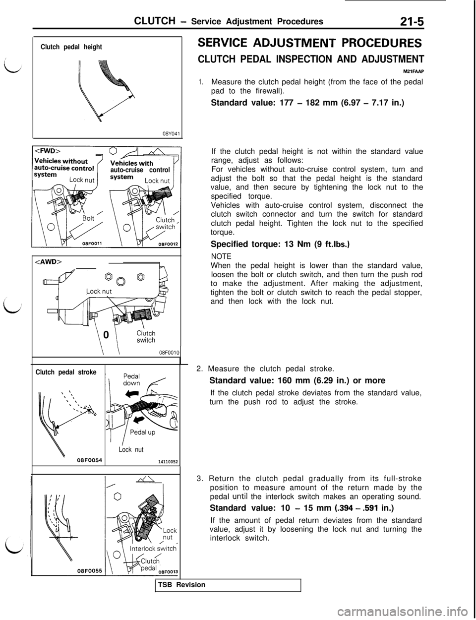
Clutch pedal height
08YO41
auto-cruise control
\ \ 0Cl;tchswitch
\ \08F0010
Clutch pedal stroke
Lock nut
08F005414110052
SERVICE ADJUSTMENT PROCEDURES
CLUTCH PEDAL INSPECTION AND ADJUSTMENTMZlFAAP
1.Measure the clutch pedal height (from the face of the pedal
pad to the firewall).
Standard value: 177
- 182 mm (6.97 - 7.17 in.)
If the clutch pedal height is not within the standard value
range, adjust as follows:
For vehicles without auto-cruise control system, turn and
adjust the bolt so that the pedal height is the standard
value, and then secure by tightening the lock nut to the
specified torque.
Vehicles with auto-cruise control system, disconnect the
clutch switch connector and turn the switch for standard
clutch pedal height. Tighten the lock nut to the specified
torque.
Specified torque: 13 Nm (9
ft.lbs.)
NOTEWhen the pedal height is lower than the standard value,
loosen the bolt or clutch switch, and then turn the push rod
to make the adjustment. After making the adjustment,
tighten the bolt or clutch switch to reach the pedal stopper,
and then lock with the lock nut.
2. Measure the clutch pedal stroke.
Standard value: 160 mm (6.29 in.) or more
If the clutch pedal stroke deviates from the standard value,
turn the push rod to adjust the stroke.
3. Return the clutch pedal gradually from its full-stroke
position to measure amount of the return made by the
pedal
u,ntil the interlock switch makes an operating sound.
Standard value: 10
- 15 mm (.394 - .591 in.)
If the amount of pedal return deviates from the standard
value, adjust it by loosening the lock nut and turning the
interlock switch.
TSB Revision
Page 364 of 1146
21-6CLUTCH - Service Adjustment Procedures
08YO4Z
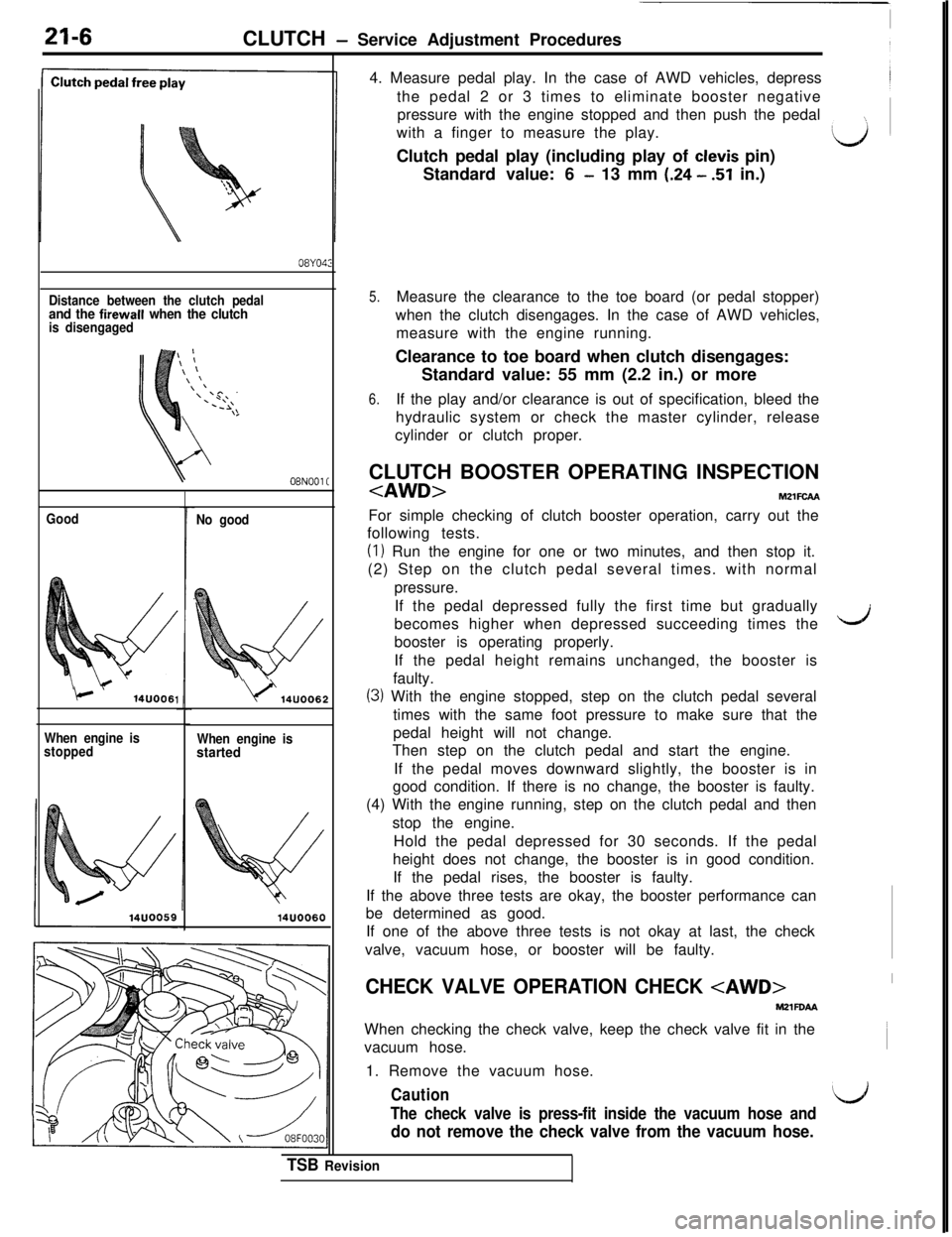
Distance between the clutch pedaland the firewall when the clutchis disengaged
08NOOl C
Good
c1‘14UOO61
When engine is
stoppedNo good
\)‘14UOO6:
When engine isstarted
14UOO604. Measure pedal play. In the case of AWD vehicles, depress~
the pedal 2 or 3 times to eliminate booster negative
pressure with the engine stopped and then push the pedal
with a finger to measure the play.
LJClutch pedal play (including play of clevis pin)
Standard value: 6
- 13 mm (.24 - 51 in.)
2
CHECK VALVE OPERATION CHECK
MZlFOAAWhen checking the check valve, keep the check valve fit in the
vacuum hose.
1. Remove the vacuum hose.
CautionL’The check valve is press-fit inside the vacuum hose and
do not remove the check valve from the vacuum hose.
5.Measure the clearance to the toe board (or pedal stopper)
when the clutch disengages. In the case of AWD vehicles,
measure with the engine running.
Clearance to toe board when clutch disengages:
Standard value: 55 mm (2.2 in.) or more
6.If the play and/or clearance is out of specification, bleed the
hydraulic system or check the master cylinder, release
cylinder or clutch proper.
CLUTCH BOOSTER OPERATING INSPECTION
following tests.
(I) Run the engine for one or two minutes, and then stop it.
(2) Step on the clutch pedal several times. with normal
pressure.
If the pedal depressed fully the first time but gradually
becomes higher when depressed succeeding times the
dbooster is operating properly.
If the pedal height remains unchanged, the booster is
faulty.
(3) With the engine stopped, step on the clutch pedal several
times with the same foot pressure to make sure that the
pedal height will not change.
Then step on the clutch pedal and start the engine.
If the pedal moves downward slightly, the booster is in
good condition. If there is no change, the booster is faulty.
(4) With the engine running, step on the clutch pedal and then
stop the engine.
Hold the pedal depressed for 30 seconds. If the pedal
height does not change, the booster is in good condition.
If the pedal rises, the booster is faulty.
If the above three tests are okay, the booster performance can
be determined as good.
If one of the above three tests is not okay at last, the check
valve, vacuum hose, or booster will be faulty.
TSB Revision
Page 365 of 1146
CLUTCH- Service Adiustment Procedures
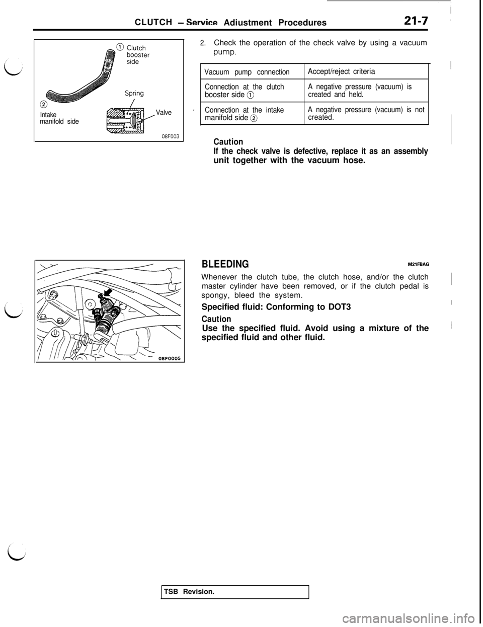
Intakemanifold sideValve
08FOO3
2.Check the operation of the check valve by using a vacuum
w-w.
Vacuum pump connectionAccept/reject criteria~
Connection at the clutchbooster side @
A negative pressure (vacuum) is
created and held.
rConnection at the intakemanifold side @
A negative pressure (vacuum) is not
created.
Caution
If the check valve is defective, replace it as an assemblyunit together with the vacuum hose.
BLEEDINGMZlFBAGWhenever the clutch tube, the clutch hose, and/or the clutch
master cylinder have been removed, or if the clutch pedal is~
spongy, bleed the system.
Specified fluid: Conforming to DOT3
CautionUse the specified fluid. Avoid using a mixture of the
specified fluid and other fluid.
TSB Revision.
Page 366 of 1146
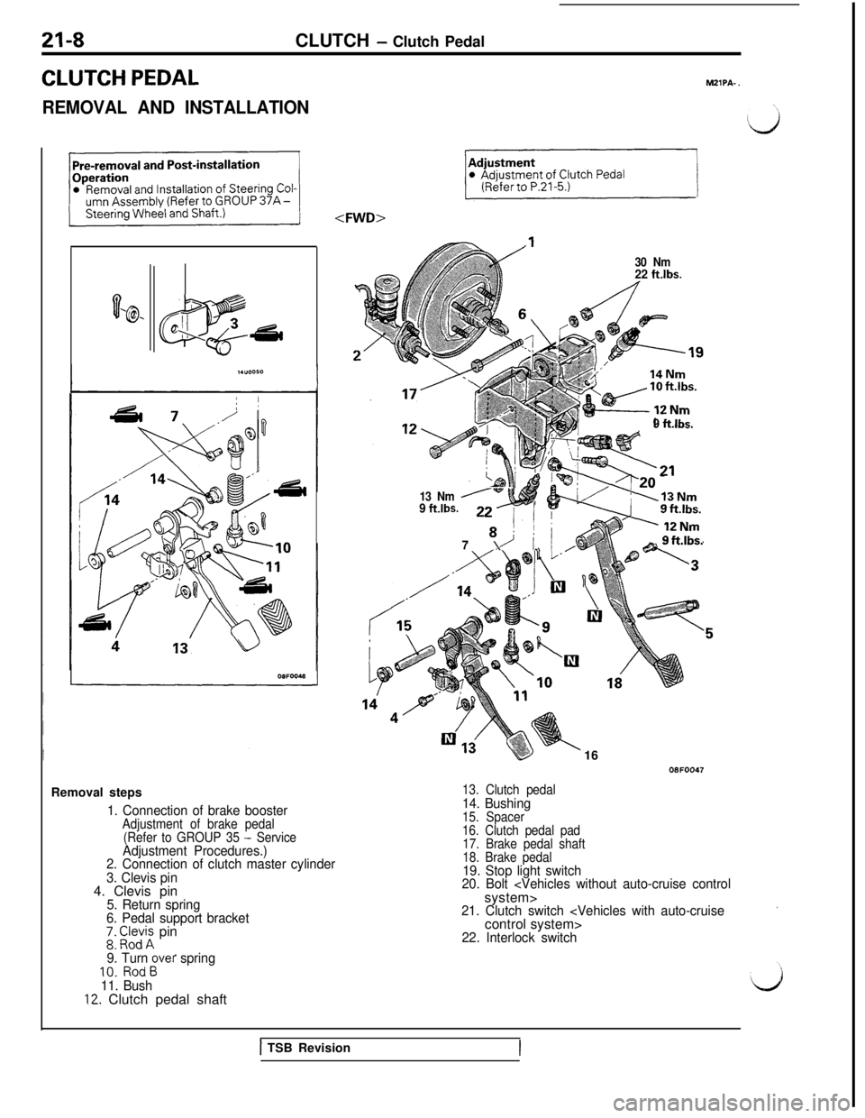
21-8CLUTCH - Clutch Pedal
CLUTCH PEDAL
REMOVAL AND INSTALLATIONMZlPA-
.
0‘@- D.,
a
;
IGsdRemoval steps
1. Connection of brake boosterAdjustment of brake pedal
(Refer to GROUP 35 - ServiceAdjustment Procedures.)
2. Connection of clutch master cylinder
3. Clevis pin4. Clevis pin
5. Return spring
6. Pedal support bracket
;: EIe;i; pin
9. Turn over spring10. RodB
11. Bush
12. Clutch pedal shaft
30 Nm22 ftlbs.
9 ft.lbs.
13 Nm
9 ft.lbs.Gw+,
8 !!
79 I_a 9ft.lbs.
k1608FOO47
13. Clutch pedal14. Bushing15. Spacer
16. Clutch pedal pad
17. Brake pedal shaft
18. Brake pedal
19. Stop light switch
20. Bolt
21. Clutch switch
22. Interlock switch
1 TSB Revision
Page 367 of 1146
IICLUTCH - Clutch Pedal
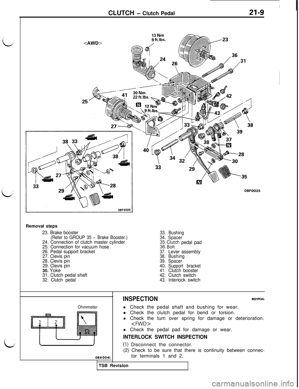
23. Brake booster(Refer to GROUP 35 - Brake Booster.)24. Connection of clutch master cylinder
25. Connection for vacuum hose
26. Pedal support bracket
27. Clevis pin
28. Clevis pin
29. Clevis pin30. Yoke
31. Clutch pedal shaft32. Clutch pedal08FOO25
33.Bushing
34.Spacer
$ E$ch pedal pad
37.Lever assembly38.Bushing
39.Spacer
40.Support bracket
41.
Clutch booster42.Clutch switch43.Interlock switch
Ohmmeter
08AOO4L
INSPECTIONMZlPCAL
l Check the pedal shaft and bushing for wear.
l Check the clutch pedal for bend or torsion.
l Check the turn over spring for damage or deterioration.
INTERLOCK SWITCH INSPECTION
(1) Disconnect the connector.
(2) Check to be sure that there is continuity between connec-
tor terminals 1 and 2.
-TSB Revision
Page 368 of 1146
a-10CLUTCH - Clutch Control
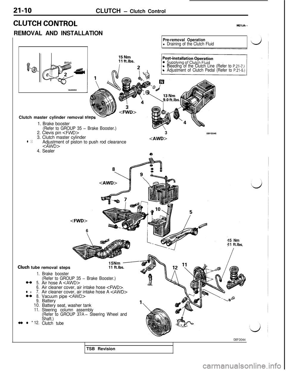
CLUTCH CONTROL
REMOVAL AND INSTALLATIONMZlJA-
-
03% J 2’ti
m
I.“0050I
Pre-removal Operationl Draining of the Clutch Fluid
l Bleeding of the Clutch Line (Refer to P.21-7.)l Adjustment of Clutch Pedal (Refer to P.21-5.)Clutch master cylinder removalstep
1. Brake booster(Refer to GROUP 35 - Brake Booster.)2. Clevis pin
4. Sealer3
9
Cluch tube
1.
**5.
6.
l +7.**8.9.IO.11.
a* l * 12.
removal steps
Brake booster15Nm
-11 ft.lbs.
(Refer to GROUP 35
- Brake Booster.)Air hose A
Battery seat, washer tank
Steering column assembly
(Refer to GROUP 37A- Steering Wheel and
Shaft.)
Clutch tube15 Nm
11
ft.lbs.
08FOO44TSB Revision
Page 369 of 1146
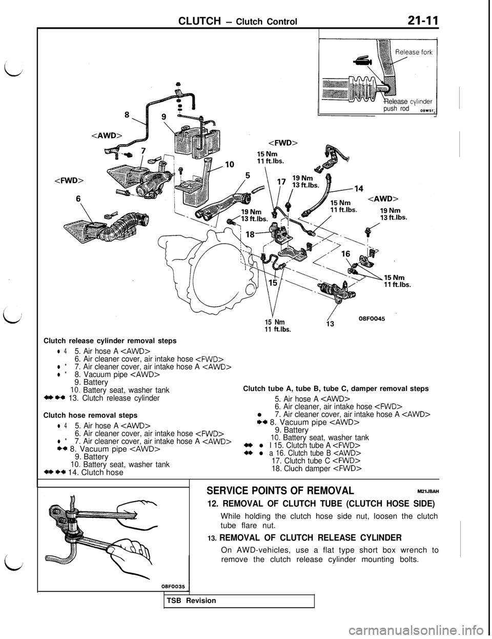
Release cylinder
push rod
txw51:
15 Nm
11 ftlbs.1308FOO45
Clutch release cylinder removal steps
l 45. Air hose A
10. Battery seat, washer tankClutch tube A, tube B, tube C, damper removal steps+* *+ 13. Clutch release cylinder
5. Air hose A
Clutch hose removal steps
6. Air cleaner, air intake hose
l 45. Air hose A
6. Air cleaner cover, air intake hose
** 8. Vacuum pipe
9. Battery+* l a 16. Clutch tube B cAWD>
10. Battery seat, washer tank17. Clutch tube C
- Clutch Control21-11
13. REMOVAL OF CLUTCH RELEASE CYLINDEROn AWD-vehicles, use a flat type short box wrench to
remove the clutch release cylinder mounting bolts.
08FOO351TSB Revision
SERVICE POINTS OF REMOVALM2lJBAH
12. REMOVAL OF CLUTCH TUBE (CLUTCH HOSE SIDE)While holding the clutch hose side nut, loosen the clutch
tube flare nut.
Page 370 of 1146
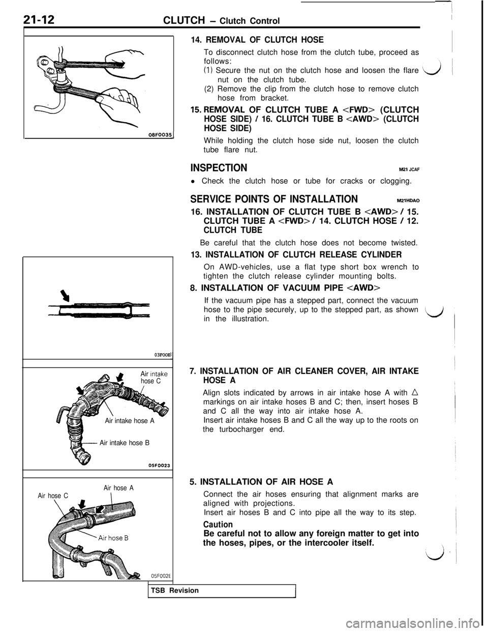
21-12CLUTCH - Clutch ControlOBFOOBf
!J
03FOOE
- Air intake hose B05FOO23
Air Intake
hose C
aAir intake hose A
Air hose CAir hose AI
05FOOZE
14. REMOVAL OF CLUTCH HOSETo disconnect clutch hose from the clutch tube, proceed as
follows:
(I) Secure the nut on the clutch hose and loosen the flare
nut on the clutch tube.
(2) Remove the clip from the clutch hose to remove clutch
hose from bracket.
15.REMOVAL OF CLUTCH TUBE A
HOSE SIDE) / 16. CLUTCH TUBE B
HOSE SIDE)While holding the clutch hose side nut, loosen the clutch
tube flare nut.
INSPECTIONM21 JCAFl Check the clutch hose or tube for cracks or clogging.
SERVICE POINTS OF INSTALLATIONM2lHDAO
16. INSTALLATION OF CLUTCH TUBE B
CLUTCH TUBE A
CLUTCH TUBEBe careful that the clutch hose does not become twisted.
13. INSTALLATION OF CLUTCH RELEASE CYLINDEROn AWD-vehicles, use a flat type short box wrench to
tighten the clutch release cylinder mounting bolts.
8. INSTALLATION OF VACUUM PIPE
hose to the pipe securely, up to the stepped part, as shown
in the illustration.
7. INSTALLATION OF AIR CLEANER COVER, AIR INTAKE
HOSE AAlign slots indicated by arrows in air intake hose A with
nmarkings on air intake hoses B and C; then, insert hoses B
and C all the way into air intake hose A.
Insert air intake hoses B and C all the way up to the roots on
the turbocharger end.
5. INSTALLATION OF AIR HOSE A
Connect the air hoses ensuring that alignment marks are
aligned with projections.
Insert air hoses B and C into pipe all the way to its step.
CautionBe careful not to allow any foreign matter to get into
the hoses, pipes, or the intercooler itself.
TSB Revision