MITSUBISHI DIAMANTE 1900 Repair Manual
Manufacturer: MITSUBISHI, Model Year: 1900, Model line: DIAMANTE, Model: MITSUBISHI DIAMANTE 1900Pages: 408, PDF Size: 71.03 MB
Page 301 of 408
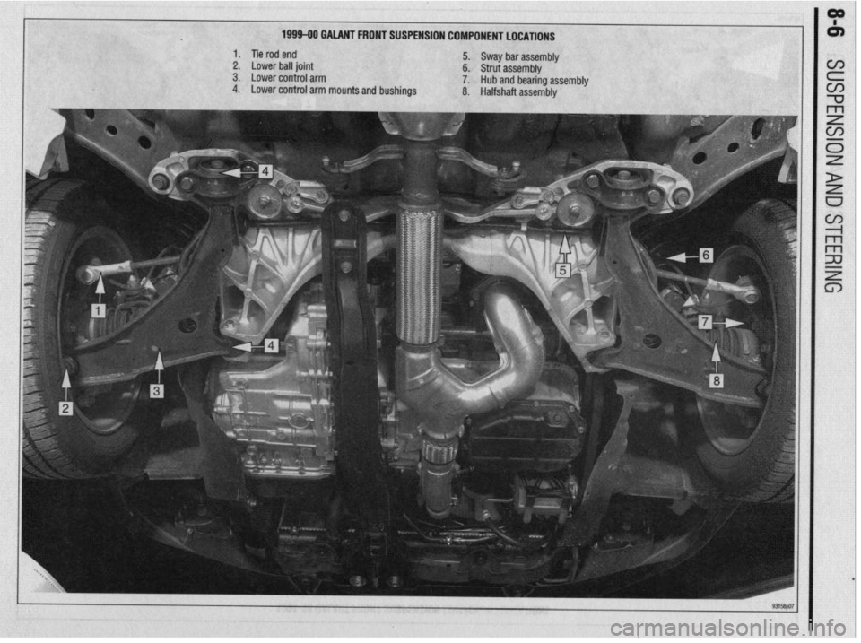
1999-90 GAIANT FRONT SUSPENSION COMPONENT LOCATIONS
1. Tie rod end
5. Sway bar assembly
2. Lower ball joint 6. Strut assembly
3. Lower control arm
7. Hub and bearing assembly
4. Lower control arm mounts and bushings
8. Halfshaft assembly
Page 302 of 408
SUSPENSION AND STEERING 8-7
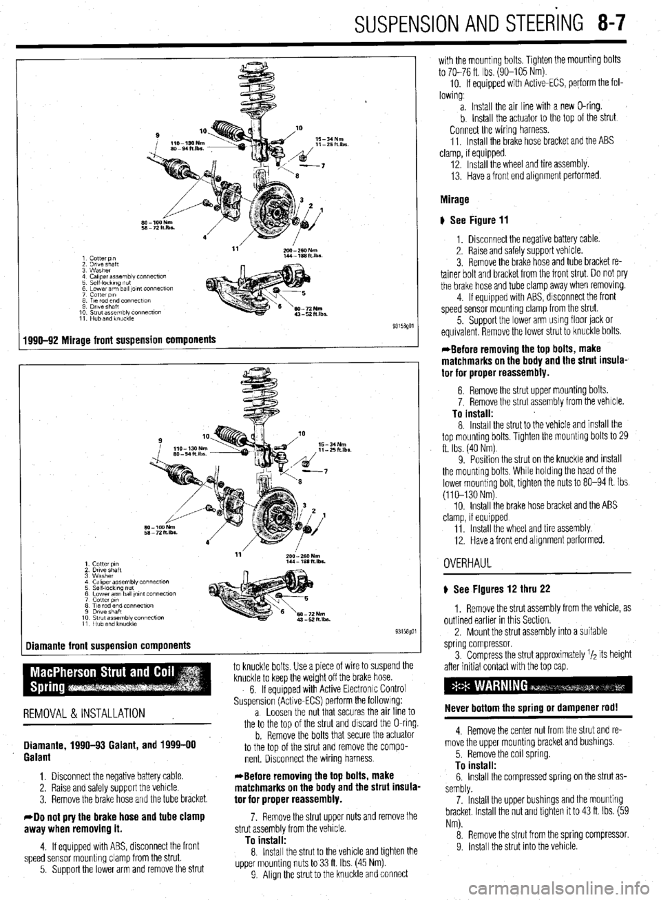
1 Cotter p,n
2 Drive shaft
3 Washer
4 Caliper assembly connecf~on
5 Self-IockIng ““f
6 Lower arm ball ,Ol”f Connectlo”
7 cotter PI”
8 T,e rod end connectton
9 Drive Shaft
10 Strut assembly connection
11 Hub and knuckle
1990-92 Mirage front suspension components
-
1 Cutter PI”
2 Drtve shaft
3 Washer
4 Ca,,perassembly connect~o”
5 Self-locking nut
6 Lower arm ball ,o,nt connection
7 cotter PI”
8 Tie rod end connection
9 Dwe shaft
10 Strut assembly connection
11 Hub and knuckie
Diamante front suspension components
1
to knuckle bolts Use a piece of wire to suspend the
knuckle to keep the weight off the brake hose.
6. If equipped with Active Electronrc Control
Suspension (Active-ECS) perform the followrng:
REMOVAL &INSTALLATION a. Loosen the nut that secures the an line to
the to the too of the strut and discard the O-ring.
Diamante, 1990-93 Galant, and 1999-00
Galant
1. Disconnect the negative battery cable.
2. Raise and safely support the vehicle.
3. Remove the brake hose and the tube bracket.
40 not pry the brake hose and tube clamp
awav when removino it.
b. Remove the bolts that secure the actuator
to the top of the strut and remove the compo-
nent. Disconnect the wiring harness.
*Before removing the top bolts, make
matchmarks on the body and the strut insula-
tor for proper reassembly.
7. Remove the strut upper nuts and remove the
strut assemblv from the vehicle.
4. If equipped with ABS, disconnect the front
speed sensor mounting clamp from the strut.
5. Support the lower arm and remove the strut
To instalf: 8. Install the strut to the vehicle and tighten the
upper mounting nuts to 33 ft. Ibs. (45 Nm)
9 Align the strut to the knuckle and connect with the mounting bolts. Tighten the mounting bolts
to 70-76 ft. Ibs. (90-105 Nm).
10. If equipped with Active-ECS, perform the fol-
lowing,
a. Install the air line with a new O-ring.
b Install the actuator to the top of the strut
Connect the wiring harness.
11. Install the brake hose bracket and the ABS
clamp, if equipped.
12. Install the wheel and tire assembly.
13. Have a front end alignment performed.
Mirage
# See Figure 11
1, Disconnect the negative battery cable.
2. Raise and safely support vehicle.
3. Remove the brake hose and tube bracket re-
tainer bolt and bracket from the front strut. Do not pry
the brake hose and tube clamp away when removrng.
4. If equipped with ABS, disconnect the front
speed sensor mounting clamp from the strut.
5. Support the lower arm usmg floor jack or
equivalent Remove the lower strut to knuckle bolts.
*Before removing the top bolts, make
matchmarks on the body and the strut insula-
tor for proper reassembly.
6. Remove the strut upper mounting bolts.
7. Remove the strut assembly from the vehicle.
To install: 8. Install the strut to the vehicle and install the
top mounting bolts, Tighten the mountrng bolts to 29
ft. Ibs. (40 Nm)
9. Position the strut on the knuckle and mstall
the mounting bolts, While holdrng the head of the
lower mounting bolt, tighten the nuts to 80-94 ft. Ibs.
(110-130 Nm).
10. Install the brake hose bracket and the ABS
clamp, if equipped
11 Install the wheel and tire assembly
12. Have a front end alignment performed.
OVERHAUL
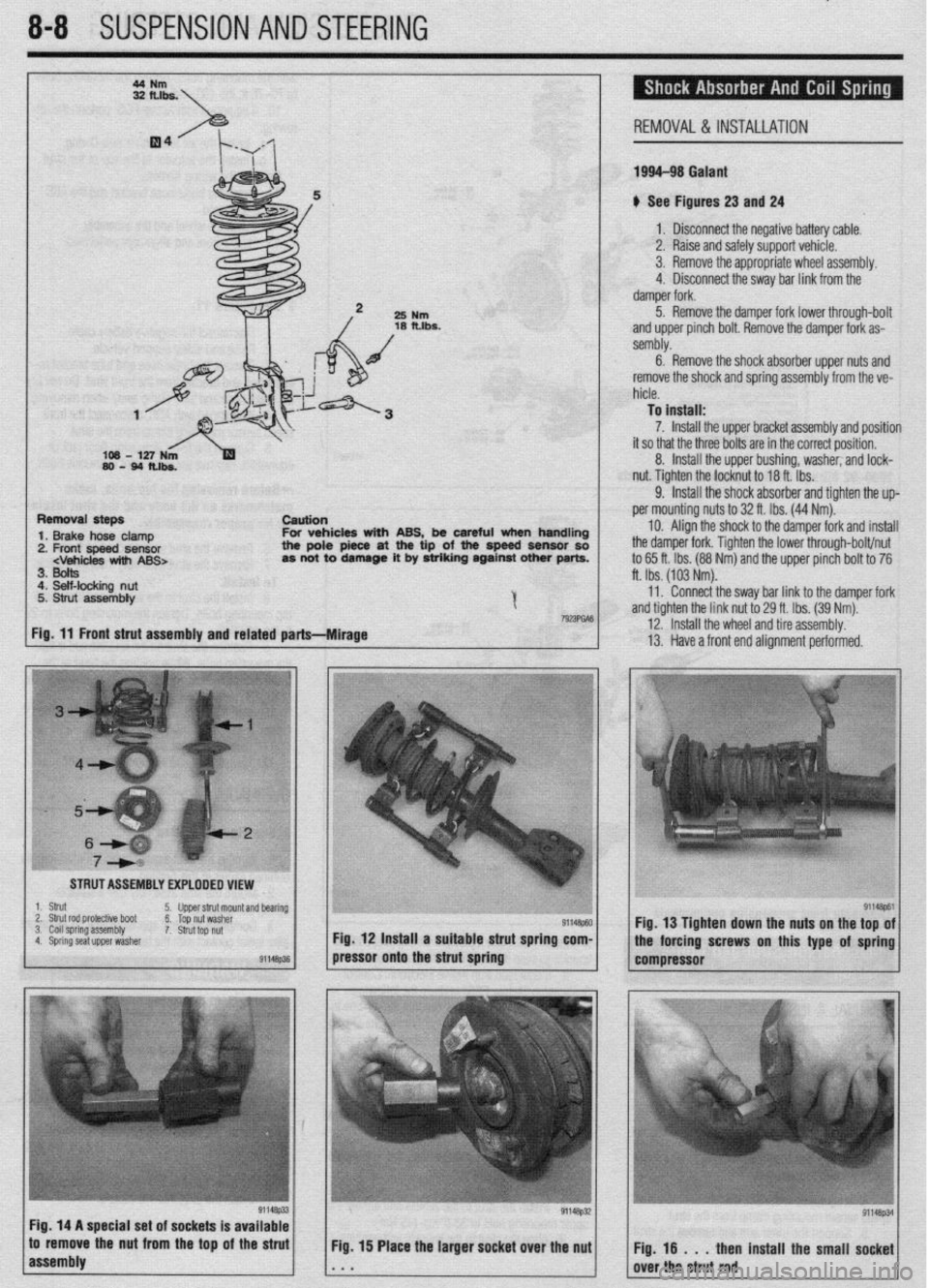
) See Figures 12 thru 22
1. Remove the strut assembly from the vehicle, as
outlined earlier in this Section.
2. Mount the strut assembly into a suitable
spring compressor.
3. Compress the strut approximately r/a its height
after initial contact with the top cap.
Never bottom the spring or dampener rod!
4. Remove the center nut from the strut and re-
move the upper mounting bracket and bushings.
5. Remove the coil spring.
To install: 6. Install the compressed spring on the strut as-
sembly.
7. Install the upper bushings and the mounting
bracket Install the nut and tighten it to 43 ft. Ibs. (59
Nm).
8. Remove the strut from the spring compressor.
9. Install the strut into the vehrcle
Page 303 of 408
8-8 SUSPENSION AND STEERING
REMOVAL &INSTALLATION
199443 Galant
u See Figures 23 and 24
1 a Disconnect the neaative batterv cable.
I 3. Remove the appronnate wheel assembly.
25
Nm
18 fths.
I 2. Raise and safelv su~oort vehicle.
I I ,I 4. Disconnect the sway bar link from the
oamper rork.
5. Remove the damper fork lower through-bolt
and upper pinch bolt. Remove the damper fork as-
sembly.
6. Remove the shock absorber upper nuts and
remove the shock and spring assembly from the ve-
hicle.
To install:
7. Install the upper bracket assembly and position
it so that the three bolts are in the correct position.
8. Install the upper bushing, washer, and lock-
nut. Tighten the locknut to 18 ft.-lbs.
9. Install the shock absorber and tighten the up-
Removal steps
csution
1. Brake hose clamp For vehicles with ABS, be careful when handling
2. Front speed sensor the pole piece at the tip of the spaed sensor so
3. Bolts
4. Self-locking nut
5. Strut assembly
I
7wmA6
Fig. 11 Front strut assembly and related parts---Mirage ft. Ibs. (103 Nm).
11. Connect the sway bar link to the damoer fork per mounting nuts to 32 ft. Ibs. (44 Nm).
IO. Align the shock to the damper fork and install
the damper fork. Tighten the lower through-bolt/nut
to 65 ft. Ibs. (88 Nm) and the upper pinch bolt to 76
and tighten the link nut tb 29 ft. Ibs. (39 Nm):
12. Install the wheel and tire assembly.
13. Have a front end alignment performed.
I STRUT ASSEMBLY EXPLODED VIEW
I ,-
:-, : ;i
,\,.^ -_ I~.’ :“:;rL~~<
-_ cy -.:;;yp;:,
91146p?Jl Fig. 12 Install a suitable strut spring com-
91146p61 Fig. 13 Tighten down the nuts on the top of
the forcing screws on this type of spring
pressor onto the strut spring
compressor
Fig. 14 A special set of sockets Is available
to remove the nut from the top of the strut
Fig. 15 Place the larger socket over the nut
1 ;ir ;;ostrut;;; install the small soi8oet
Page 304 of 408
SUSPENSION AND STEER'ING 8-9
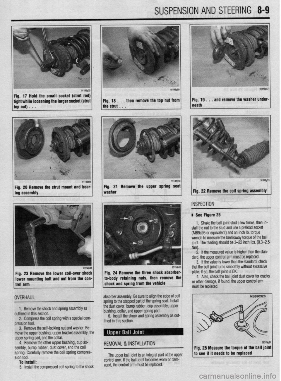
ile loosening the larger socket (strut then remove the top nut from
91148ps4 1 Fig. 29 Remove the strut mount and bear-
ins assembly 1 Fig. 21 Remove the upper spring seat 1
washer
91148PS7
Fig. 19 . t , and remove the washer under-
neath
Fig. 22 Remove the coil spring assembly
INSPECTION
’ ) See Figure 25
Fig. 23
Remove the lower coil-over shock
lowar mounting bolt
and nut from the con- 1.
Shake the ball joint stud a few times, then in-
stall the nut to the stud and use a preload socket
(MB9c26 or equivalent) and an inch lb. torque
wrench to measure the breakaway torque of the ball
joint. The reading should be 3-22 inch Ibs. (0.3-2.5
Nm).
2.
If the measured value is higher than the stan-
dard, the upper control arm must be replaced.
3.
If the value is lower than the standard, check
that the ball joint turns smoothly without excessive
Fig. 24 Remove the three shock absorber- plate. If so, the ball joint is OK. to-body retaining nuts, the 4.
Also, check the ball joint dust cover for cracks
or other damage, if found, the upper control arm
must be replaced.
1.
outlin
OVERHAUL
Remove the shock and spring assembly as
ed in this section.
Compress the coil spring with a special com-
ion tool.
Remove the self-locking nut and washer. Re-
the upper bushing, upper bracket assembly, the
sorina oad. and the collar. absorber assembly. Be sure to align the edge of coil
sorina to the steoaed Dart of the spring Seat. laSk3ll assembly, upper
nad
2.
press
3.
move
upper
4. dem&e the other upper bushing, cup as-
sembly, bump rubber, dust I cover, and the coil
spring. Carefully remove the coil spring compres-
sion tool.
To install:
5. Install the compressed coil spring to the shock
REMOVAL &INSTALLATION
Thp lwwr hall inint is an inkoral oart of the umer
6e d&cover, d;mp iubber, cup
bushing, collar, and upper spring r--.
6. Install the shock and spring assembly as out-
lined in this section.
Fig. 25 Measure the toruue of the ball joint
to see if it needs to be t&laced
..*., “rf.l’ “m.. ,-.,.. .--.. . ...-=.- r-. . .rr
control arm. If the ball joint becomes worn or dam-
aged, the control arm must be replaced.
Page 305 of 408
‘. . ^ .s ”
840 SUSPENSION ANY ik%iiiG
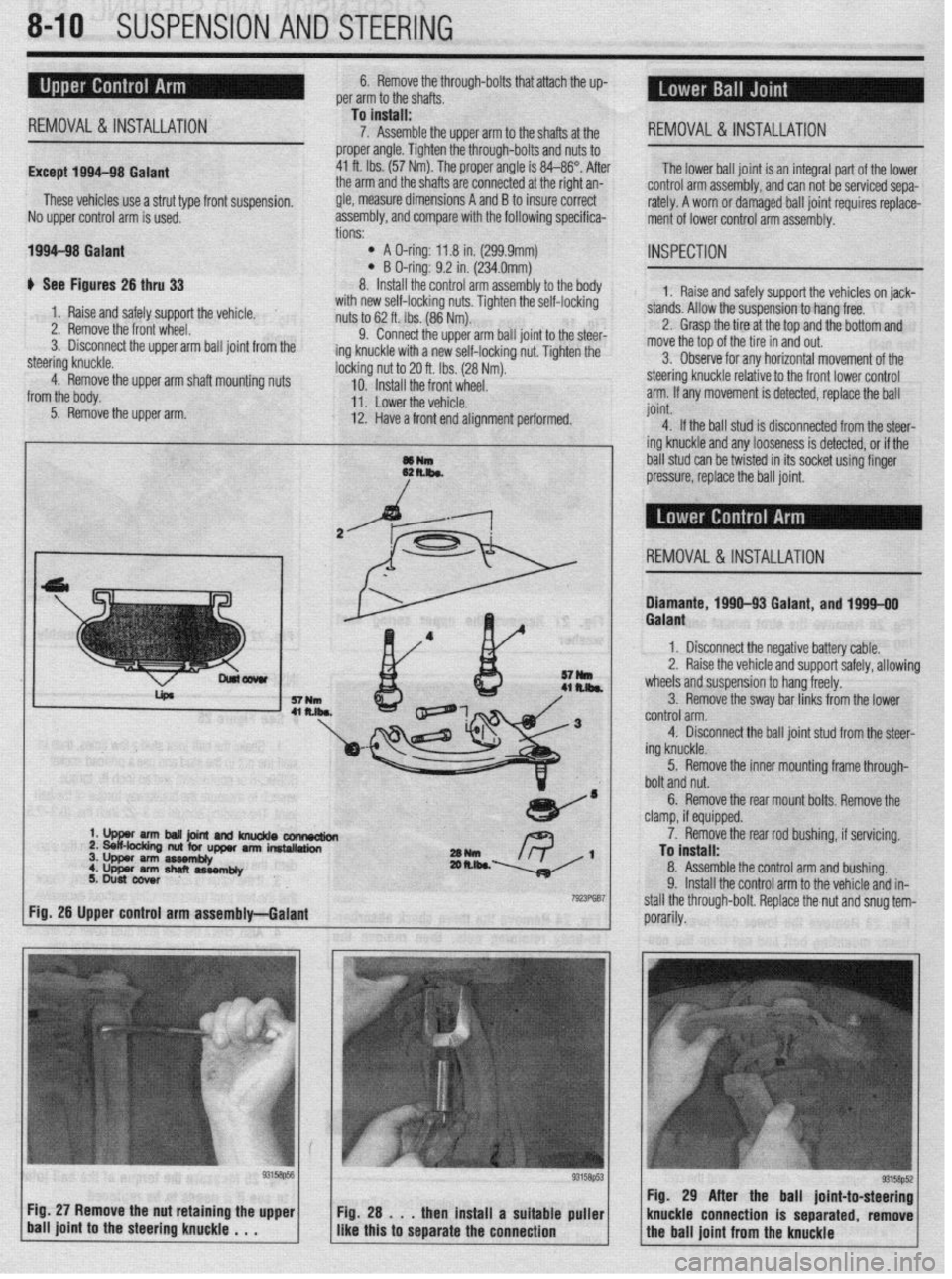
6. Remove thethrough-bolts that attach the up-
per arm to the shafts , . , ,
Except 199
REMOVAL&INSTALLATION
M-98 Galant
These vehicles use a strut type front suspension,
No uooer control arm is used.
1994-98 Galant
# See Figures 26 thru 33 tions: -
l A O-ring: 11.8 in. (299.9mm) l B O-ring: 9.2 in. (234.0mm)
8. Install the control arm ass
To install:
7. Assemble the upper arm to the shafts at the
proper angle. Tighten the through-bolts and nuts to
41 ft. Ibs. (57 Nm). The proper angle is 84-86”. After
the arm and the shafts are connected at the right an-
gle, measure dimensions A and B to insure correct
assembly, and comoare with the following specifica- REMOVAL& INSTALLATION
The lower ball joint is an integral part of the lower
control arm assembly, and can not be serviced sepa-
rately. A worn or damaged ball joint requires replace-
ment of lower control arm assembly.
embly to the body
_ IL_ --at I-., ..-
INSPECTION
1. Raise and safely support the vehicles on jack-
with new self-locking nuts. Tighten one sea-rockrng
nuts to 62 ft. Ibs. (86 Nm).
9. Connect the upper arm ball joint to the steer-
ing knuckle with a new self-locking nut. Tighten the
locking ^_ ~. I- -
10.
11 . L”WCl LI It: “Cl Illx.
12. Have
a front end alinnmen
nut to 20 ft. Ibs. (28 Nm). ve for any horizontal movement of the
Install the front wheel. steering knuckle relative to the front lower control
I ml.,,.* ,I.+. .,^l.:^l^ arm. If any movement is detected, replace the ball
t performed. joint.
---g -
4. If the ball stud is disconnected from the steer-
ing knuckle and any looseness is detected, or if the
~~ k hall dir! ran ho twiatm-l in itr cnrlmt II&WI finnnr ““.I VLVV “Yll YY L..l”L”” #II IIU UY”I\“L u.l,,,y ““y”’
/ pressure, replace the ball joint, stands. Allow the suspension to hang free.
2. Grasp the tire at the top and the bottom and
move the tar
3. Obser 1. Raise and safely support the vehicle.
2. Remove the front wheel.
3. Disconnect the upper arm ball joint from the
steering knuckle.
4. Remove the upper arm shaft mounting nuts
from the body.
5. Remove the upper arm.
d REMOVAL &INSTALLATION
rck ,-.-.
Diamante, 1990-93 Galant, and 1994-00
3. Remove the sway bar links from the lower
..^^l-^l ^--
titJIILIlJI alIll. 4. Disconnect the bail joint stud from the steer-
ing knuckle.
5. Remove the inner mounting frame through-
bolt and nut.
6. Remove the rear mount bolts. Remove the
clamp, if equipped.
‘YUN
- ,-. R \_ 1 2m.lk~ -
7923Fw7
7. Remove the rear rod bushing, if servicing.
To install:
8. Assemble the control arm and bushing.
9. Install the control arm to the vehicle and in-
stall the through-bolt. Replace the,nut and snua tem-
porarily. - 1 Fig. 26 Upper control arm assembly-Galant
Fig. 27 Remove the nut retaining the upper
1 ball joint to the steering knuckle , . . Fig. 29 A
Fig. 28 . , . then install a suitable puller
I I knuckle COI
like this to separate the connection Galant
1, Disconnect the negative battery cable.
2. Raise the vehicle and support safely, allowing
wheels and suspension to hang freely.
Page 306 of 408
SUSPENSION AND STEERING 8-11
-*i-
7928685
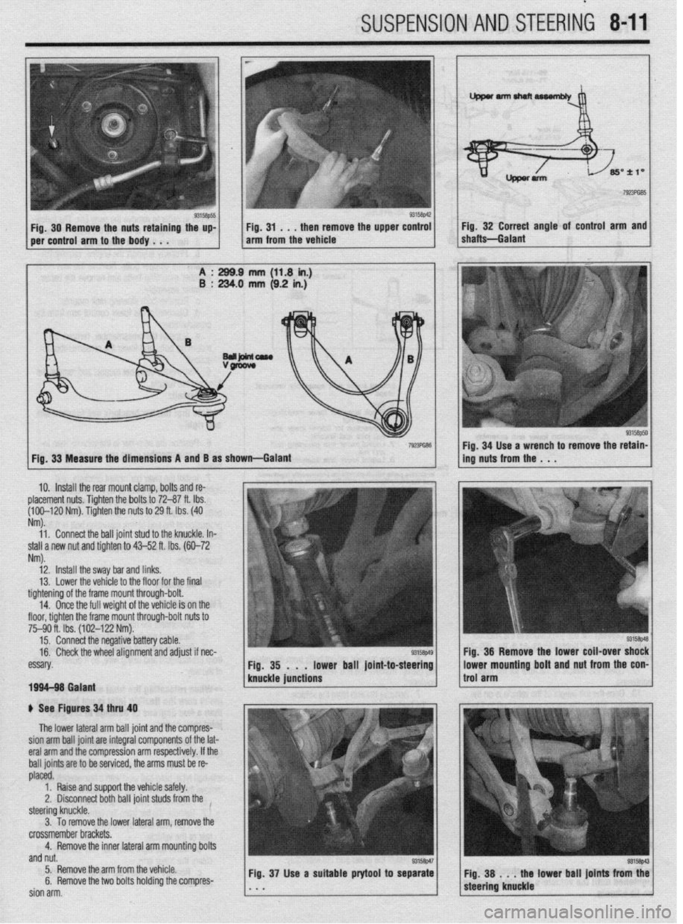
g3’w5 Fig, 30 Remove the nuts retaining the up-
per control arm to the body . . . I$ ;A, -;h$re~ove the upper co;:; 1 Fig 32 Correct angle of control arm and
shaftsGa,ant
ench to remove the
retain-
1. Connect the ball joint stud to the knuckle.
In-
Nm).
12. Install the sway bar and links.
13.
Lower the vehicle to the floor for the final
tightening of the frame mount through-bolt.
14.
Once the full weight of the vehicle is on the
floor, tighten the frame mount through-bolt nuts to
75-90 ft. Ibs. (102-122 Nm).
15. Connect the negative battery cable.
16. Check the wheel alignment and adjust if nec-
essary
1994-98 Galant
) See Figures 34 thru 40
The lower lateral arm ball joint and the compres-
sion arm ball joint are integral components of the lat-
eral arm and the compression arm respectively. If the
ball joints are to be serviced, the arms must be re-
placed.
1.
Raise and support the vehicle safely.
2, Disconnect both ball joint studs from the
steering knuckle.
3. To remove the lower lateral arm, remove the
crossmember brackets.
4. Remove the inner lateral arm mounting bolts
and nut.
5.
Remove the arm from the vehicle.
6. Remove the two bolts holding the compres-
sion arm. Fig. 37 Use
a suitable prytool to separate
the lower ball
joints from the
Page 307 of 408
8-12 SUSPENSION AND STEERING
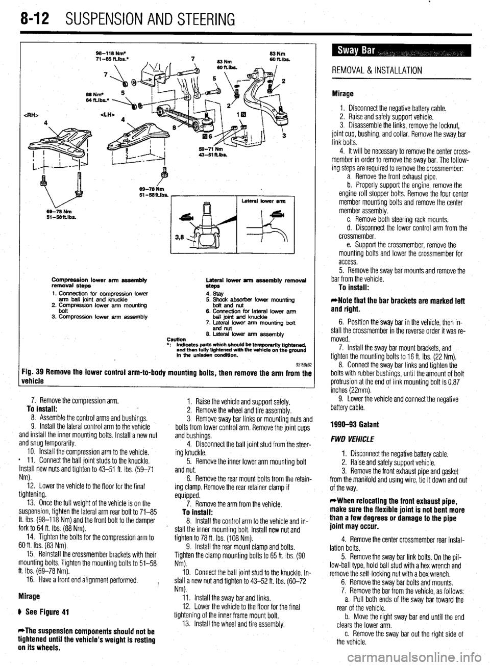
Compression lower an assembly
removal steps Lateral lower arm assembly removal
Hcps
1. Connection for compression lower
arm ball joint and knuckle
2. Compressron lower arm mounting
bolt
3. Compression lower arm assembly 4. stay
5. ~mdtsoorber lower mounting
6. Connection for lateral lower arm
ball joint and knuckle
7. Metal lower arm mounting bolt
end nut
6. Lateral low% arm assemblv
CSUtlOll
l : Indicates parts wfdch should k temporarily tightened,
and then fully tightened with fhe vehicle on the ground
in the unladen wndluon.
93158p62 :ig. 39 Remove the lower control arm-to-body mounting bolts, then remove the arm from the
rehicle
8. Assemole me control arms and bushmgs. 7. Remove the compression arm,
^. To install:
Y. Install the lateral control arm to the vehicle
and install the inner mounting bolts. Install a new nut
and snug temporarily. -. .*.. a.
10. Install the compression arm to the vehicle.
* 11. Connect the ball joint studs to the knuckle.
Install new nuts and tighten to 43-51 ft. Ibs (59-71
Nm).
12. Lower the vehicle to the floor for the final
tightening. 3. Remove sway bar links or mounting nuts and
bolts from lower control arm. Remove the joint cups 1.
and bushings.
4. Raise the vehicle and support safely.
Disconnect the ball joint stud from the steer-
ing knuckle. 2. Remove the wheel and tire assembly
13. Once the full weight of the vehicle is on the
suspension, tighten the lateral arm rear bolt to 71-85
ft. Ibs. (98-118 Nm) and the front bolt to the damper
fork to 64 ft. Ibs. (88 Nm).
14. Tighten the bolts for the compresslon arm to
60 ft. Ibs. (83 Nm).
15. Reinstall the crossmember brackets with their
mounting bolts. Tighten the mounting bolts to 51-58
ft. Ibs. (69-78 Nm).
16. Have a front end alignment performed.
Mirage
ti See Figure 41
*The suspension components should not be
tightened until the vehicle’s weight is resting
on its wheels. 5. Remove the inner lower arm mounting bolt
and nut.
6. Remove the rear mount bolts from the retain-
ing clamp. Remove the rear retainer clamp if
equipped.
7. Remove the arm from the vehicle.
To install:
8. Install the control arm to the vehicle and in-
stall the inner mounting bolt. Install new nut and
tighten to 78 ft. Ibs. (108 Nm).
9. Install the rear mount clamp and bolts.
Tighten the clamp mounting bolts to 65 ft. Ibs. (90
Nm).
10. Connect the ball joint stud to the knuckle. In-
stall a new nut and tighten to 43-52 ft. Ibs. (60-72
Nm).
11. Install the sway bar and links.
12. Lower the vehicle to the floor for the final
tightening of the inner frame mount bolt.
13. Install the wheel and tire assembly.
REMOVAL&INSTALLATION
Mirage
1. Disconnect the negative battery cable.
2. Raise and safely support vehicle.
3. Disassemble the links, remove the locknut,
joint cup, bushing, and collar. Remove the sway bar
link bolts.
4. It will be necessary to remove the center cross-
member in order to remove the sway bar. The follow-
ing steps are required to remove the crossmember:
a. Remove the front exhaust pipe
b. Properly support the engine, remove the
engine roll stopper bolts. Remove the four center
member mounting bolts and remove the center
member assembly.
c. Remove both steering rack mounts.
d. Disconnect the lower control arm from the
crossmember,
e. Support the crossmember, remove the
mounting bolts and lower the crossmember for
access.
5. Remove the sway bar mounts and remove the
bar from the vehicle.
To install:
*Note that the bar brackets are marked left
and right.
6. Position the sway bar in the vehicle, then in-
stall the crossmember in the reverse order it was re-
moved.
7. Install the sway bar mount brackets, and
tighten the mounting bolts to 16 ft. Ibs. (22 Nm).
8. Connect the sway bar links and tighten the
bolts with rubber bushings, until the amount of bolt
protrusion at the end of link mounting bolt is 0.87
inches (22mm).
9. Lower the vehicle and connect the negative
battery cable.
1990-93 Galant
FWD VEHICLE
1. Disconnect the negative battery cable.
2. Raise and safely support vehicle.
3. Remove the front exhaust pipe and gasket
from the manifold and using wire, tie it down and out
of the way.
WWhen relocating the front exhaust pipe,
make sure the flexible joint is not bent more
than a few degrees or damage to the pipe
joint may occur.
4. Remove the center crossmember rear instal-
lation bolts.
5. Remove the sway bar link bolts. On the pil-
low-ball type, hold ball stud with a hex wrench and
remove the self-locking nut with a box wrench.
6. Remove the sway bar bolts and mounts.
7. Remove the bar from the vehicle, as follows:
a. Pull both ends of the sway bar toward the
rear of the vehicle.
b. Move the right sway bar end until the end
clears the lower arm.
c. Remove the sway bar out the right side of
the vehicle.
Page 308 of 408
SUSPENSION AND STEERING 8-13
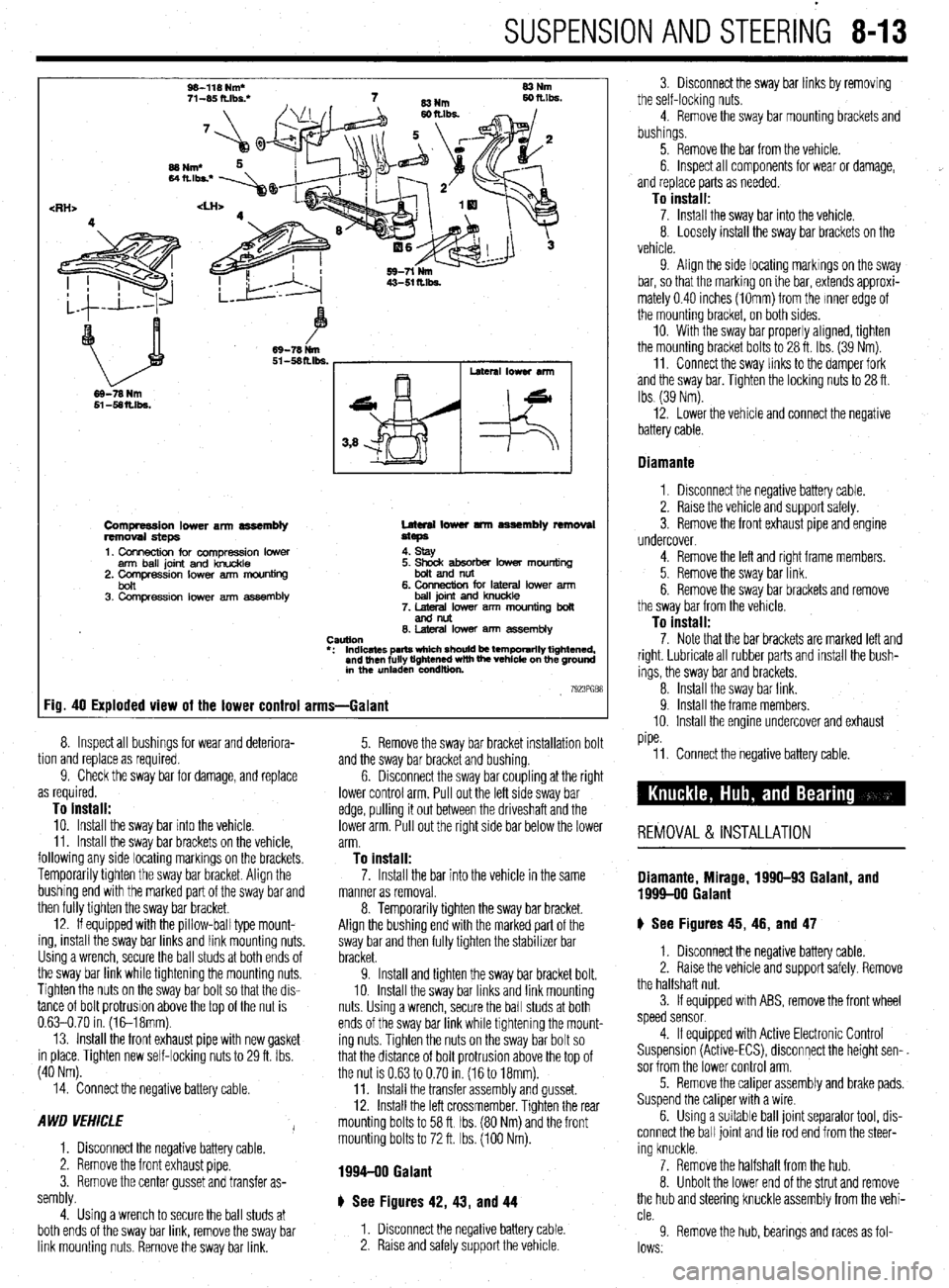
W-118 Nm*
71-W ft.lbs: 83Nm
69-78 Nm
Compression lower arm assembly
removal steps
1. Connection for compression lower
arm ball joint and knuckle
2. Comoression lower arm mouniina Lateral lower tmn assembly removal
steps
4. stay
bon ’ 3. Compression lower arm assembly 6. CMlnection for lateral lower arm
ball joint and knuckle
7. lateral lower arm mounting boll
andnllt
0. hleral lower am7 assembly
CWtlOtl
l : Indicates parts which should be temporarily tightened,
and then fully tightened with the vehicle on the ground
in the unladen condition
7923PGB8 Fig. 40 Exploded view of the lower control arms-Galant
tion and replace as required. 8.
9. Inspect all bushings for wear and deteriora-
Check the sway bar for damage, and replace
as required.
To install: 10. Install the sway bar into the vehicle.
11. Install the sway bar brackets on the vehicle,
following any side locating markings on the brackets.
Temporarily tighten the sway bar bracket. Align the
bushing end with the marked part of the sway bar and
then fully tighten the sway bar bracket.
12. If equipped with the pillow-ball type mount-
ing, install the sway bar links and link mounting nuts.
Using a wrench, secure the ball studs at both ends of
the sway bar link while tightening the mounting nuts.
Tighten the nuts on the sway bar bolt so that the dis-
tance of bolt protrusion above the top of the nut is
0.63-0.70 in. (1&18mm).
13. Install the front exhaust pipe with new gasket
in place. Tighten new self-locking nuts to 29 ft. Ibs.
(40 Nm). and the sway bar bracket and bushing.
6. 5. Remove the sway bar bracket installation bolt
Disconnect the sway bar coupling at the right
lower control arm. Pull out the left side sway bar
edge, pulling it out between the driveshaft and the
lower arm. Pull out the right side bar below the lower
arm.
To install:
14. Connect the negative battery cable.
A WD VEHICLE
I
1. Disconnect the negative battery cable.
2. Remove the front exhaust pipe.
3. Remove the center gusset and transfer as-
sembly.
4. Using a wrench to secure the ball studs at
both ends of the sway bar link, remove the sway bar
link mounting nuts. Remove the sway bar link. 11. Connect the negative battery cable.
REMOVAL & INSTALLATION
7. Install the bar into the vehicle in the same Diamante, Mirage, 1996-93 Galant, and manner as removal. 1999-00 Galant 8. Temporarily tighten the sway bar bracket.
Align the bushing end with the marked part of the
sway bar and then fully tighten the stabilizer bar
bracket.
9. Install and tighten the sway bar bracket bolt.
10. Install the sway bar links and link mounting
nuts Using a wrench, secure the ball studs at both
ends of the sway bar link while tightening the mount-
ing nuts. Tighten the nuts on the sway bar bolt so
that the distance of bolt protrusion above the top of
the nut is 0.63 to 0.70 in. (16 to 18mm).
11. Install the transfer assembly and gusset.
12. Install the left crossmember. Tighten the rear
mounting bolts to 58 ft Ibs. (80 Nm) and the front
mounting bolts to 72 ft. Ibs. (100 Nm). ) See Figures 45, 46, and 47
1. Disconnect the negative battery cable.
2. Raise the vehicle and support safely. Remove
the halfshaft nut.
3. If equipped with ABS, remove the front wheel
speed sensor
1994-90 Galant
4. If equipped with Active Electronic Control
Suspension (Active-ECS), disconnect the height sen-.
sor from the lower control arm.
5. Remove the caliper assembly and brake pads.
Suspend the caliper with a wire
6. Using a suitable ball joint separator tool, dis-
connect the ball joint and tie rod end from the steer-
ing knuckle.
7. Remove the halfshaft from the hub.
8. Unbolt the lower end of the strut and remove
the hub and steering knuckle assembly from the vehi-
cle.
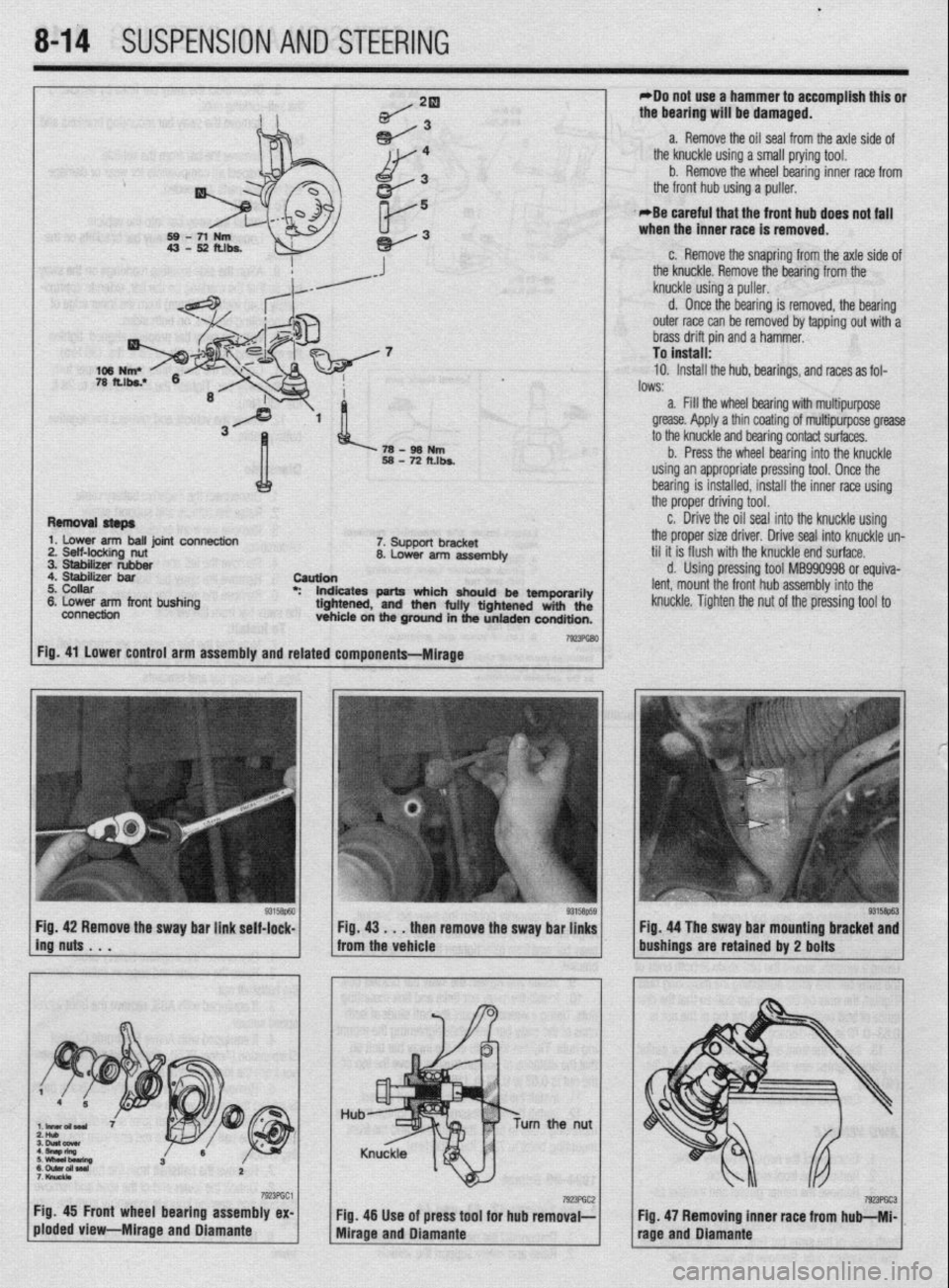
9 Remove the hub, bearings and races as fol-
lows.
# See Figures 42, 43, and 44
1. Disconnect the negative battery cable.
2. Raise and safely support the vehicle 3. Disconnect the sway bar links by removing
the self-locking nuts.
4. Remove the sway bar mounting brackets and
bushings.
5. Remove the bar from the vehicle.
6. Inspect all components for wear or damage,
and replace parts as needed.
To install: 7. Install the sway bar into the vehicle.
8. Loosely install the sway bar brackets on the
vehicle.
9. Align the side locating markings on the sway
bar, so that the marking on ihe bar, extends approxi-
mately 0.40 inches (1Omm) from the Inner edge of
the mounting bracket, on both sides.
10. With the sway bar properly aligned, tighten
the mounting bracket bolts to 28 ft. Ibs. (39 Nm).
11. Connect the sway links to the damper fork
and the sway bar. Tighten the locking nuts to 28 ft.
Ibs (39 Nm).
12. Lower the vehicle and connect the negative
battery cable.
Diamante
1. Disconnect the negative battery cable.
2. Raise the vehicle and support safely.
3. Remove the front exhaust pipe and engine
undercover.
4. Remove the left and right frame members.
5. Remove the sway bar link.
6. Remove the sway bar brackets and remove
the sway bar from the vehicle.
To install: 7. Note that the bar brackets are marked left and
right. Lubricate all rubber parts and install the bush-
ings, the sway bar and brackets.
8. Install the sway bar link.
9. Install the frame members.
10. Install the engine undercover and exhaust
pipe.
Page 309 of 408
.
8-14 SUSPENSION AND STEERING
*Do not use a hammer to accomplish this or
the bearing will be damaged.
a. Remove the oil seal from the axle side of
the knuckle using a small prying tool.
b. Remove the wheel bearing inner race frorr
the front hub using a puller.
. -Be careful that the front hub does not fall
when the inner race is removed.
108 N ?a fu c. Remove the snapring from the axle side 01
the knuckle. Remove the bearing from the
knuckle UI **
;rng a purrer.
d. One e the bearing is removed, the bearing
outer race can be removed by tapping out with-a
brass drift pin and a hammer.
To install:
10. Install the hub, bearings, and races as fol-
lows:
a. Fill the wheel bearing with multipurpose
grease. Apply a thin coating of multipurpose greas
+- +hn L”S?kle and bearina contact surfaces.
L” u lC N IUI b. Pre: is the wheel bearing into the knuckle
using an a #ppropriate pressing tool. Once the
bearing is
installed, install the inner race using
the proper driving tool.
c. Drivi
e the oil seal into the knuckle using
the proper size driver. Drive seal into knuckle un
til it is flush with the knuckle end surface.
d. Using pressing tool MB990998 or equiva-
lent, mount the front hub assembly into the
knuckle. Tighten the nut of the pressing tool to
:tg. 41 Lower control arm assembly and related components-Mirage Remrnml stsps
1. Lower arrn ball joint connection
2. Self-locking nut
3. Stabilizer rubber
4. Stabilizer bar
5. Collar
8. Lower arm front bushing
connection --?8-98Nm
58-72ft.b.
7. Support bracket
8. Lower arm assembly
Caution
*: lndkates parts which should be temporarily
tightened, and then fully tightensd with the
vehicle on the ground in the unladen condition.
1 ing’nuts . . . 9315Bp63
Fig 42 Remove the sway bar link self-lock- Q3158p60 1 1 :;izi . ..t$i yovy the sway ba~~~~~ 1. / . Fig 44 The sway bar mounting bracket and
bushings are retained by 2 bolts ,,,,
I I I’ r
urn the nut
7923PGC1 Fig, 45 Front wheel bearing assembly ex-
ploded View-Mirage and Diamante 7923PGC2 Fig. 46 Use of press tool for hub removal--
Mirage and Diamante 79wGc3 Fig. 47 Removing inner race from hub-Ml-
rage and Diamante
Page 310 of 408
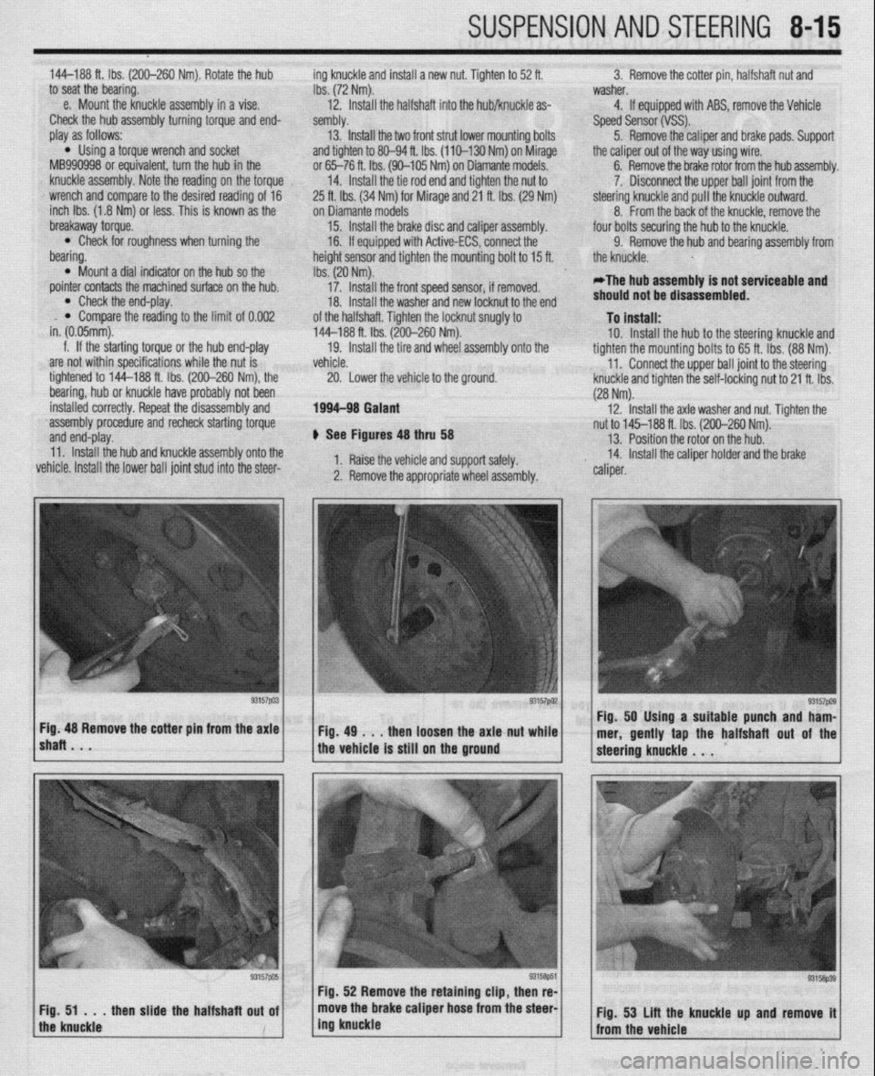
SUSPENSION AND STEERING 845
144-188 ft. Ibs. (200-260 Nm). Rotate the hub ing knuckle and install a new nut. Tighten to 52 ft. 3. Remove the cotter pin, halfshaft nut and
to seat the bearing.
Ibs. (72 Nm). washer.
e. Mount the knuckle assembly in a vise.
12. Install the halfshaft into the hub/knuckle as- 4. If equipped with ABS, remove the Vehicle
Check the hub assembly turning torque and end- sembly.
Speed Sensor (VSS).
play as follows: 13. Install the two front strut lower mounting bolts
5. Remove the caliper and brake pads. Support
l Using a torque wrench and socket
and tighten to 80-94 ft. Ibs. (110-130 Nm) on Mirage
the caliper out of the way using wire.
MB990998 or equivalent, turn the hub in the or 65-76 ft. Ibs. (90-105 Nm) on Diamante models. 6. Remove the brake rotor from the hub assembly.
knuckle assembly. Note the reading on the torque
14. Install the tie rod end and tighten the nut to 7. Disconnect the upper ball joint from the
wrench and compare to the desired reading of 16
25 ft. lbs. (34 Nm) for Mirage and 21 ft. Ibs. (29 Nm) steering knuckle and pull the knuckle outward.
inch Ibs. (1.8 Nm) or less. This is known as the ‘on Diamante models
8. From the back of the knuckle, remove the
breakaway torque.
15. Install the brake disc and caliper assembly. ‘four bolts securing the hub to the knuckle.
l Check for roughness when turning the
16. If equipped with Active-ECS, connect the
9. Remove the hub and bearing assembly from
bearing.
height sensor and tighten the mounting bolt to 15 ft.
the knuckle.
0 Mount a dial indicator on the hub so the
Ibs. (20 Nm).
pointer contacts the machined surface on the hub.
17. Install the front speed sensor, if removed.
*The hub assembly is not serviceable and
l Check the end-play.
18. Install the washer and new locknut to the end should not be disassembled.
l Compare the reading to the limit of 0.002
in. (0.05mm). of the halfshaft. Tighten the locknut snugly to To install: 144-188 ft. Ibs. (200-260 Nm).
f. If the starting torque or the hub end-play
19. Install the tire and wheel assembly onto the 10. Install the hub to the steering knuckle and
are not within specifications while the nut is tighten the mounting bolts to 65 ft. Ibs. (88 Nm).
vehicle.
11.
tightened to 144-188 ft. Ibs. (200-260 Nm), the
Lower the vehicle to the ground. Connect the upper ball joint to the steering
20.
bearing, hub or knuckle have probably not been ‘knuckle and tighten the self-locking nut to 21 ft. Ibs.
(28 Nm).
installed correctly. Repeat the disassembly and 1994-98 Galant 12.
‘assembly procedure and recheck starting torque Install the axle washer and nut. Tighten the
and end-play. nut to 145-188 ft. Ibs. (200-260 Nm).
+ See Figures 48 thru 58 13. Position the rotor on the hub.
11. Install the hub and knuckle assembly onto the
vehicle. Install the lower ball joint stud into the steer- 1. Raise the vehicle and support safely. 14. Install the caliper holder and the brake
2. Remove the appropriate wheel assembly. ” caliper.
lshaRBmV * “57pa3~ ~Fig.4g~..thenloosehtheaxlattut~~;.~ Fig. 48 Remove the cotter pm from the axle Fig. 50 Using a suitable punch and ham-
mer, gently tap the halfshaft out of the
the vehicle is still on the ground