MITSUBISHI DIAMANTE 1900 Repair Manual
Manufacturer: MITSUBISHI, Model Year: 1900, Model line: DIAMANTE, Model: MITSUBISHI DIAMANTE 1900Pages: 408, PDF Size: 71.03 MB
Page 311 of 408
8116 SUSPENSION AND STEERING
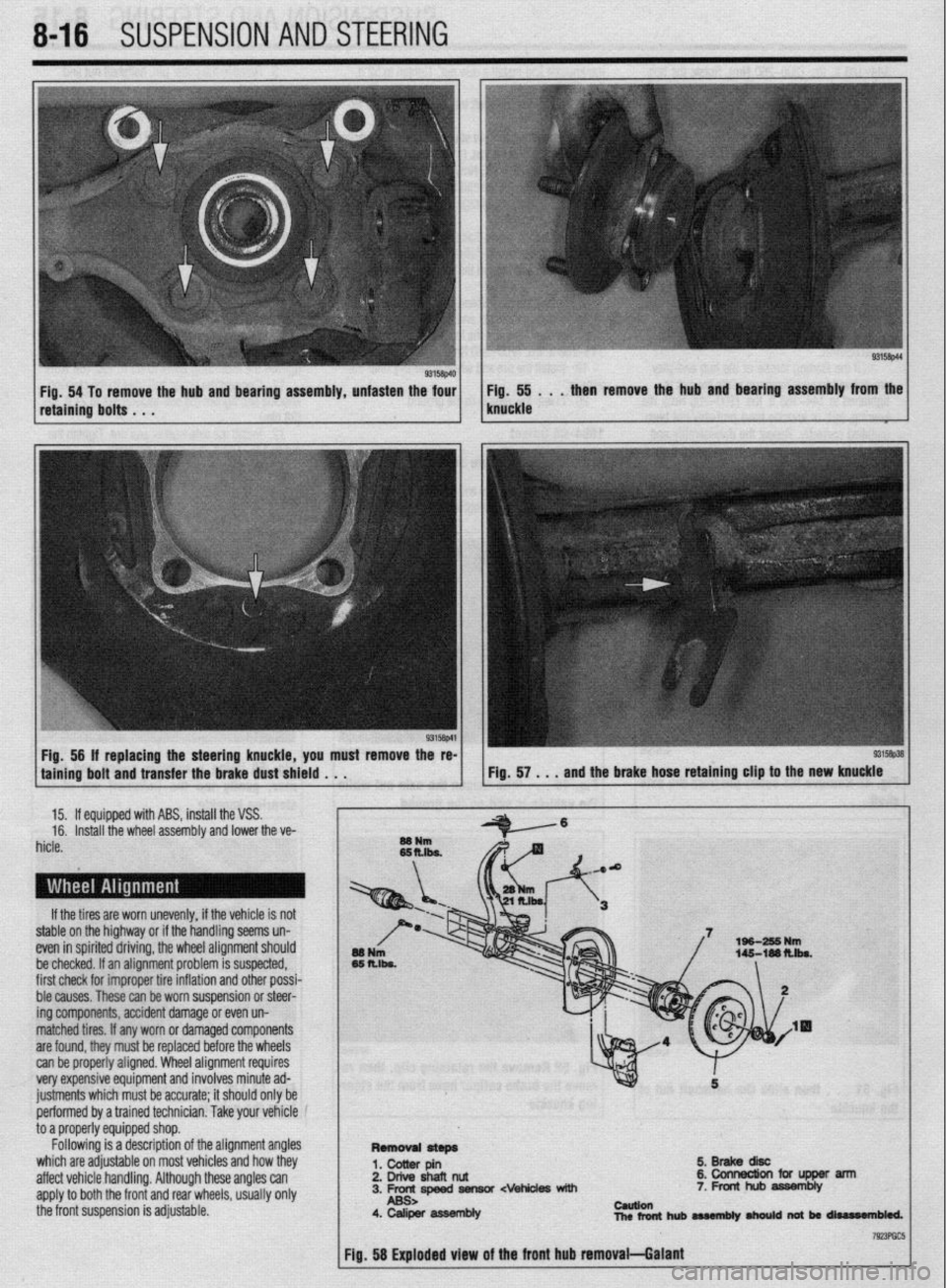
Fig. 54 To remove the hub and bearing assembly, unfasten the four Fig. 55 . . . then remove the hub and bearing assembly from the
retaining bolts . . . knuckle
Fig, 56 If replacing the steering knuckle, you must remove the re-
taining bolt and transfer the brake dust shield . . .
15. If equipped with ABS, install the VSS.
16. Install the wheel assembly and lower the ve-
hicle.
If the tires are worn unevenly, if the vehicle is not
stable on the highway or if the handling seems un-
even in spirited driving, the wheel alignment should
be checked. If an alignment problem is suspected,
first check for improper tire inflation and other possi-
ble causes. These can be worn suspension or steer-
ing components, accident damage or even un-
matched tires. If any worn or damaged components
are found, they must be replaced before the wheels
can be properly aligned. Wheel alignment requires
very expensive equipment and involves minute ad-
justments which must be accurate; it should only be
performed by a trained technician. Take your vehicle
to a properly equipped shop.
Following is a description of the alignment angles
which are adjustable on most vehicles and how they
affect vehicle handling. Although these angles can
apply to both the front and rear wheels, usually only
the front suspension is adjustable.
5.BrakediW
2. Drive shafl nut &collnectionfciflJpperarm
3. Frc-rc,speed fiensor cvehides with 7. Front hub assembly
4. Caliper asWmbly cauuen
nlcrfonthubaMmbly~natbrrliurr#n61ed.
Page 312 of 408
SUSPENSION AND STEERING 8-17
CASTER
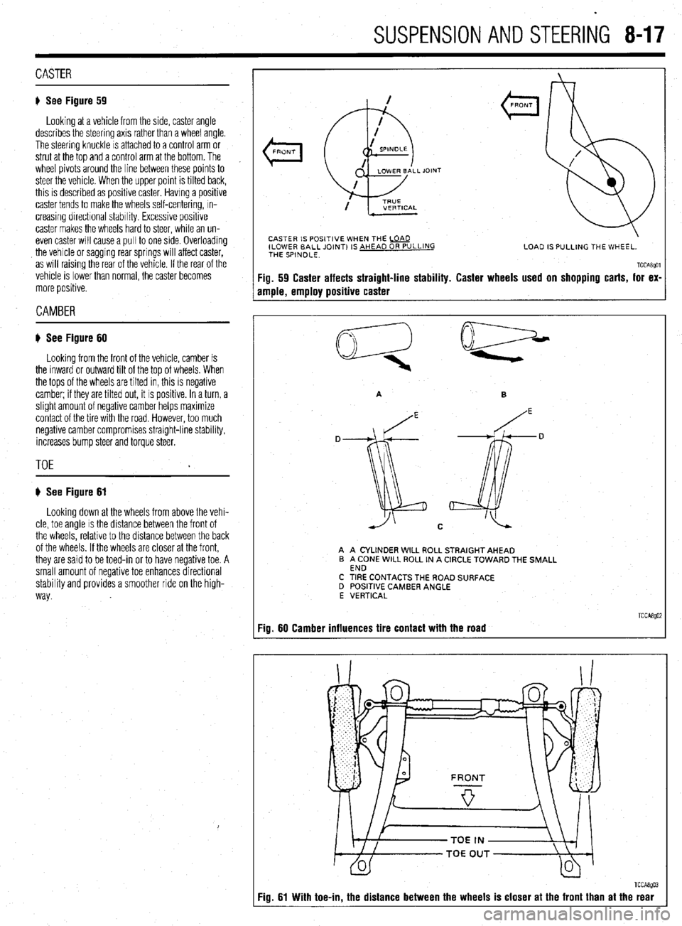
) See Figure 59
Looking at a vehicle from the side, caster angle
describes the steering axis rather than a wheel angle.
The steering knuckle is attached to a control arm or
strut at the top and a control arm at the bottom. The
wheel pivots around the line between these points to
steer the vehicle. When the upper point is tilted back,
this is described as positive caster. Having a positive
caster tends to make the wheels self-centering, in-
creasing directional stability. Excessive positive
caster makes the wheels hard to steer, while an un-
even caster will cause a pull to one side. OVerlOading
the vehicle or sagging rear springs will affect caster,
as will raising the rear of the vehicle. If the rear of the
vehicle is lower than normal, the caster becomes
more positive.
CAMBER
# See Figure 60
Looking from the front of the vehicle, camber is
the inward or outward tilt of the top of wheels. When
the tops of the wheels are tilted in, this is negative
camber; if they are tilted out, it is positive. In a turn, a
slight amount of negative camber helps maximize
contact of the tire with the road. However, too much
negative camber compromises straight-line stability,
increases bump steer and torque steer.
TOE
) See Figure 61
Looking down at the wheels from above the vehi-
cle, toe angle is the distance between the front of
the wheels, relative to the distance between the back
of the wheels. If the wheels are closer at the front,
they are said to be toed-in or to have negative toe. A
small amount of negative toe enhances directional
stability and provides a smoother ride on the high-
way.
< FRONT
CASTER IS POSITIVE WHEN THE La
ILOWER BALL JOINT) IS AHEAD OR PULLING
THE SPINDLE. LOAD IS PULLING THE WHEEL.
TCCABgOl Fig. 59 Caster affects straight-line stability. Caster wheels used on shopping carts, for ex-
ample, employ positive caster
D
A A CYLINDER WILL ROLL STRAIGHT AHEAD
B A CONE WILL ROLL IN A CIRCLE TOWARD THE SMALL
END
C TIRE CONTACTS THE ROAD SURFACE
D POSITIVE CAMBER ANGLE
E VERTICAL
TCCABgOi :ig. 60 Camber influences tire contact with the road
Fig. 61 With toe-in, the distance between the wheels is closer at the front than at the rear
Page 313 of 408
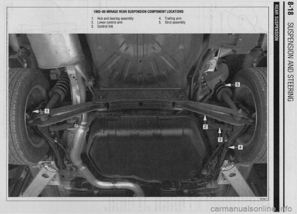
1993-90 MIRAGE REAR SUSPENSION COMPONENT LOCATIONS
1.
Hub and bearing assembly 4. Trailing arm
2. Lower control arm 5. Strut assembly
3. Control link
Page 314 of 408
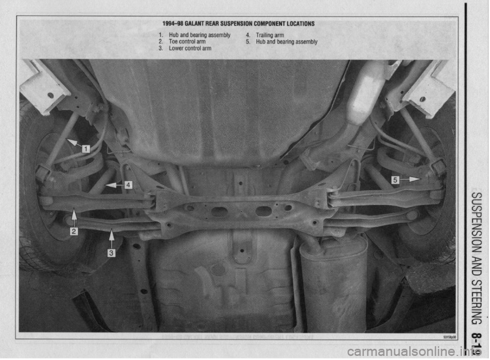
1994-98 GALANT REAR SUSPENSION COMPONENT LOCATIONS
1. Hub and bearing assembly 4. Trailing arm
2. Toe control arm 5. Hub and bearina assemblv
II
3. Lower control arm
Page 315 of 408
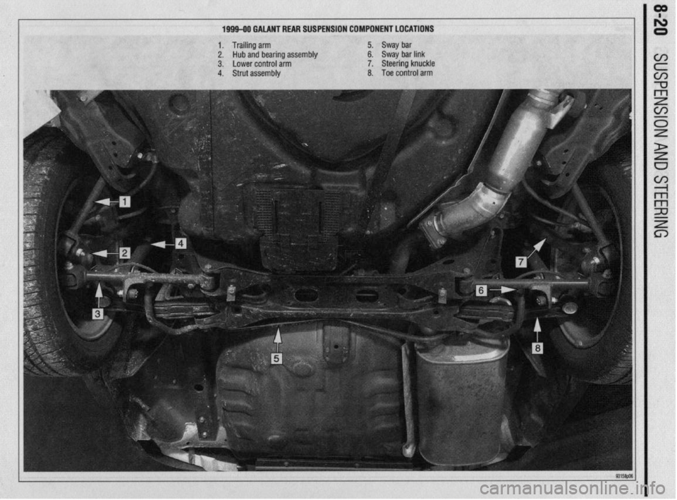
199940 GALANT REAR SUSPENSION COMPONENT LOCATIONS
1. Trailing arm
5.
Sway bar
2.
Hub and bearing assembly 6. Sway bar link
3. Lower control arm
7.
Steering knuckle
4. Strut assembly
8.
Toe control arm
Page 316 of 408
.
SUSPENSION AND STEERING 8-21
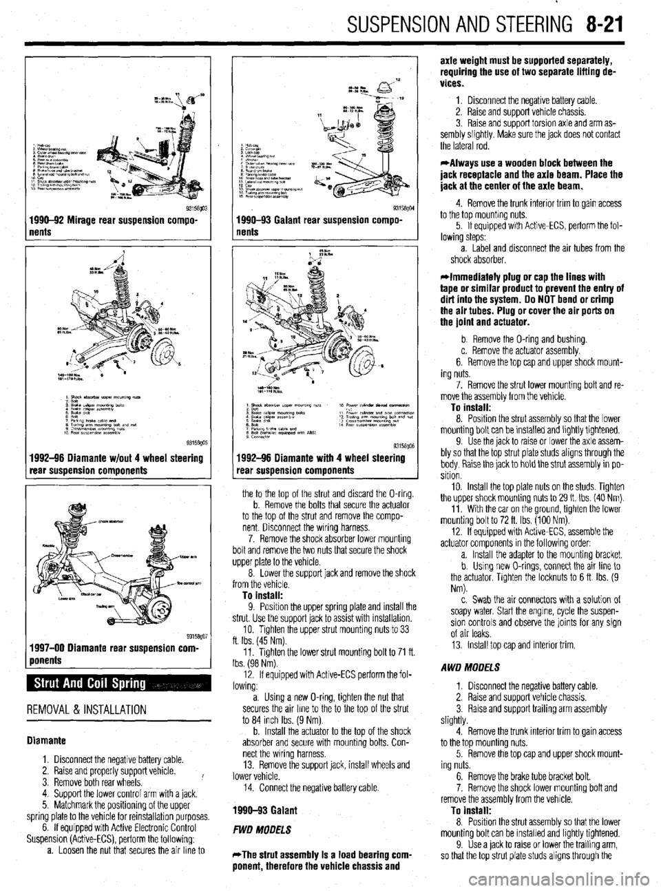
1 nents Q3158!@3 1990-92 Mirage rear suspension compo-
1992-96 Diamante w/out 4 wheel steering
rear suspension components
1 ponents %” 1997-00 Diamante rear suspension corn
REMOVAL & INSTALLATION
Diamante
1. Disconnect the negative battery cable.
2. Raise and properly support vehicle.
3. Remove both rear wheels. !
4. Support the lower control arm with a jack.
5. Matchmark the positioning of the upper
spring plate to the vehicle for reinstallation purposes.
6. If equipped with Active Electronic Control
Suspension (Active-ECS), perform the following:
a. Loosen the nut that secures the air line to
I
93158QM 1990-93 Galant rear suspension compo-
nents
1992-96 Diamante with 4 wheel steering
rear suspension components
the to the top of the strut and discard the O-ring.
b. Remove the bolts that secure the actuator
to the top of the strut and remove the compo-
nent Disconnect the wiring harness.
7. Remove the shock absorber lower mounting
bolt and remove the two nuts that secure the shock
upper plate to the vehicle.
8. Lower the support jack and remove the shock
from the vehicle.
To install:
9. Position the uooer sprina elate and install the
strut. Use the support’jack to as% with installation.
10. Tighten the upper strut mounting nuts to 33
ft. Ibs. (45 Nm).
11. Tighten the lower strut mounting bolt to 71 ft.
Ibs. (98 Nm).
12. If equipped with Active-ECS perform the fol-
lowing:
a. Using a new O-ring, tighten the nut that
secures the air line to the to the top of the strut
to 84 inch Ibs. (9 Nm).
b. Install the actuator to the top of the shock
absorber and secure with mounting bolts. Con-
nect the wiring harness.
13. Remove the support jack, install wheels and
lower vehicle.
14. Connect the negative battery cable.
1990-93 Galant
FWD MODELS
*The strut assembly Is a load bearing com-
ponent, therefore the vehicle chassis and axle weight must be supported separately,
requiring the use of two separate lifting de-
vices.
1. Disconnect the negative battery cable.
2. Raise and support vehicle chassis.
3. Raise and support torsion axle and arm as-
sembly slightly. Make sure the jack does not contact
the lateral rod.
*Always use a wooden block between the
jack receptacle and the axle beam. Place the
jack at the center of the axle beam.
4. Remove the trunk interior trim to gain access
to the top mounting nuts.
5. If equipped with Active-ECS, perform the fol-
lowing steps:
a. Label and disconnect the air tubes from the
shock absorber.
*Immediately plug or cap the lines with
tape or similar product to prevent the entry of
dirt into the system. Do NOT bend or crimp
the air tubes. Plug or cover the air ports on
the joint and actuator.
b. Remove the O-ring and bushing.
c. Remove the actuator assembly.
6. Remove the top cap and upper shock mount-
ing nuts.
7. Remove the strut lower mounting bolt and re-
move the assembly from the vehicle.
To install:
8. Position the strut assembly so that the lower
mounting bolt can be installed and lightly tightened.
9. Use the jack to raise or lower the axle assem-
bly so that the top strut plate studs aligns through the
body. Raise the jack to hold the strut assembly in po-
sition
10. Install the top plate nuts on the studs. Tighten
the upper shock mounting nuts to 29 It. Ibs. (40 Nm).
11. With the car on the ground, tighten the lower
mounting bolt to 72 ft. Ibs. (100 Nm).
12. If equipped with Active-ECS, assemble the
actuator components in the following order:
a. Install the adapter to the mounting bracket.
b. Using new O-rings, connect the air line to
the actuator, Tighten the locknuts to 6 ft Ibs. (9
Nm).
c. Swab the air connectors with a solution of
soapy water. Start the engine, cycle the suspen-
sion controls and observe the joints for any sign
of air leaks.
13. Install top cap and interior trim.
AWD MODELS
1. Disconnect the negative battery cable.
2. Raise and support vehicle chassis.
3. Raise and support trailing arm assembly
slightly.
4. Remove the trunk interior trim to gain access
to the top mounting nuts.
5. Remove the top cap and upper shock mount-
ing nuts.
6. Remove the brake tube bracket bolt.
7. Remove the shock lower mounting bolt and
remove the assembly from the vehicle.
To install:
8. Position the strut assembly so that the lower
mounting bolt can be installed and lightly tightened.
9. Use a jack to raise or lower the trailing arm,
so that the top strut plate studs aligns through the
Page 317 of 408
sembly slightly.
3. In order to gain access to the top mounting
nuts, remove the rear seat as follows:
r
I-- a. While pulling the rear seat stopper out- lb
ward, lift the lower cushion upward. Remove the
lower cushion.
b. Remove the seat back mounting bolts.
c. Lift the seat back upward and remove the
seat.
4. Remove the shock upper mounting nuts.
5. Remove the shock lower mounting bolt and
remove the assembly from the vehicle.
To install:
6. Position the shock assembly so that the
lower mounting bolt can be installed and lightly
tightened.
7. Use a jack to raise or lower the lower control
arm, so that the top shock plate studs align through
the body. Raise the jack to hold the shock assembly
in position.
8 “, In&dl the tnn nlato nl Itc: nn thp dl~rk nnri ,,,“Lu,l .,,” .“* r....” ,.“.., “.. . ..” -.I__-..” tighten the mounting nuts to 32 ft. Ibs. (44 Nm).
9. With the vehicle on the ground, tighten the
lower mounting bolt to 71 ft. Ibs. (98 Nm).
10. Install the rear seat back and cushion.
Miraae
I
1. Remove the trunk interior trim to aain access
to the top mounting nuts.
2. Remove the top cap and upper shock mount-
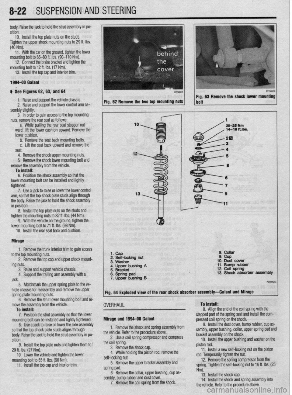
I 1. cap
2 Beif-locking nut
Q* ,A,ll)rrr ii ZPb
10: Dust cbver
11. Bump rubber 12. Coil spring
8-22 SUSPENSION AND STEERING
,
I
ing nuts.
3. Raise andsupport vehicle chassis.
4. Support the trailing arm assembly with a
iack a. ““QJ1vw
;. ~~;~~inp A
6: Spring pad 7. Upper bushing B 13. Shock absorber assembly
I----. 5 Matchmark thF! unner snrino elate to the ve-
I TmFliBl
_. .._._....._... . .._ -TT- _r
u r _.- .-
hicle chassis for reassembly and remove the upper
spring plate mounting nuts.
^ ^
. . .a .I II. I Fig. 64 Exploded view of the rear shock absorber assembly-Galant and Mirage
I
-t
Inrmg DOII ana re-
9.
OVERHAUL To Install:
o A*. .* I b. nemove tne strut lower mol
move the assembly from the vehicle
To install:
7. Position the strut assembly so that the lower
mountino bolt can be installed and liahtlv tiahtened.
8. t&e a jack to raise or lower thk &le&sembly
so that the top shock plate studs aligns through
body. Raise the jack to hold the strut assembly in po-
sition.
9. Install the top plate nuts and tighten them to
20 ft. Ibs. (27 Nm).
mounting bolt to 65 ft. Ibs. (90 Nm).
11. Install the top cap and interior trim. Mirage and 1996-00 Galant 0. ,,ngn me ena of the coil spring with the
stepped part of the spring seat and install the com-
pressed cnil snrinn nn the shock
1. Remove the shock and spring assembly from
the vehicle. Refer to the procedure above.
2. Use a coil spring compressor and compress
the coil spring.
3. Remove the shock cap.
” \w.;,n hrrh~inn +I-.- n;r+nn rnr( rnmn,rc, thn ,. .,,,,,- ,,-,-,* *J ..l” r .I._. * .-_, .-...-.- . ..-
self-locking nut.
5. Remove the upper bracket assembly and
spring pad.
6. Remove the collar, upper bushing, cup as-
sembly, bump rubber and dust cover.
7. Remove the coil spring from the shock. _.. -r,.. J _ _ _ __
9. Install the dust cover, bump rubber, cup as-
sembly, upper bushing, collar, upper spring pad and
bracket assembly on the shock.
10. Install the upper bushing and washer on the
piston rod.
11. Install a new self-locking nut on the piston
roa. temporarily tighten the nut.
12. Remove the spring compressor from the
spring. Tighten the self-locking nut to 16 ft. Ibs. (25
Nm).
13. Install the shock cap.
14. Install the shock and spring assembly into
the v&i&a Rnfnr tn the nmrd~w~ ahnrm
Page 318 of 408
SUSPENSION AND STEERING 8-23
i-l
12. Check rear wheel alignment and adjust if nec-
REMOVALANDINSTALLATION
essary.
1990-93 Galant
1. Disconnect the neoative battetv cable.
2. Raise and safely sipport vehicle.
3. Remove the tire and wheel assembly.
4. Support the rear lower control arm.
5. Remove the brake line clamp bolt.
6. Remove the nut and separate the upper ball
joint, using tool MB9f35 or equivalent, from the rear
trailing arm/steering knuckle.
*It is important to use proper method of
joint separation when reusing joint. Damage
can result from unapproved methods, result-
ing in possible joint failure.
7. Matchmark the eccentric nn the IInner instal-
8. Remove the upper arm from the vehicle.
To install:
9. Install the arm to the vehicle and install the
upper arm installation bolt. Align the matchmarks
and tighten the nut snugly only.
10. Install the upper arm ball joint to the rear
spindle assembly and install new nut. Tighten to 52
ft. Ibs. (72 Mm).
11. Install the tire and wheel assembly.
12. Lower the vehicle until the suspension sup-
ports its weight.
13. Tighten the upper arm installation bolt to 116
ft. Ibs. (160 Nmj. 1. Disconnect the negative battery cable.
- . .._...- -.. . ..- -rr-. lation bolt and remove from the control arm.
14. ‘Check the rear wheel alignment.
1994-98 Galant
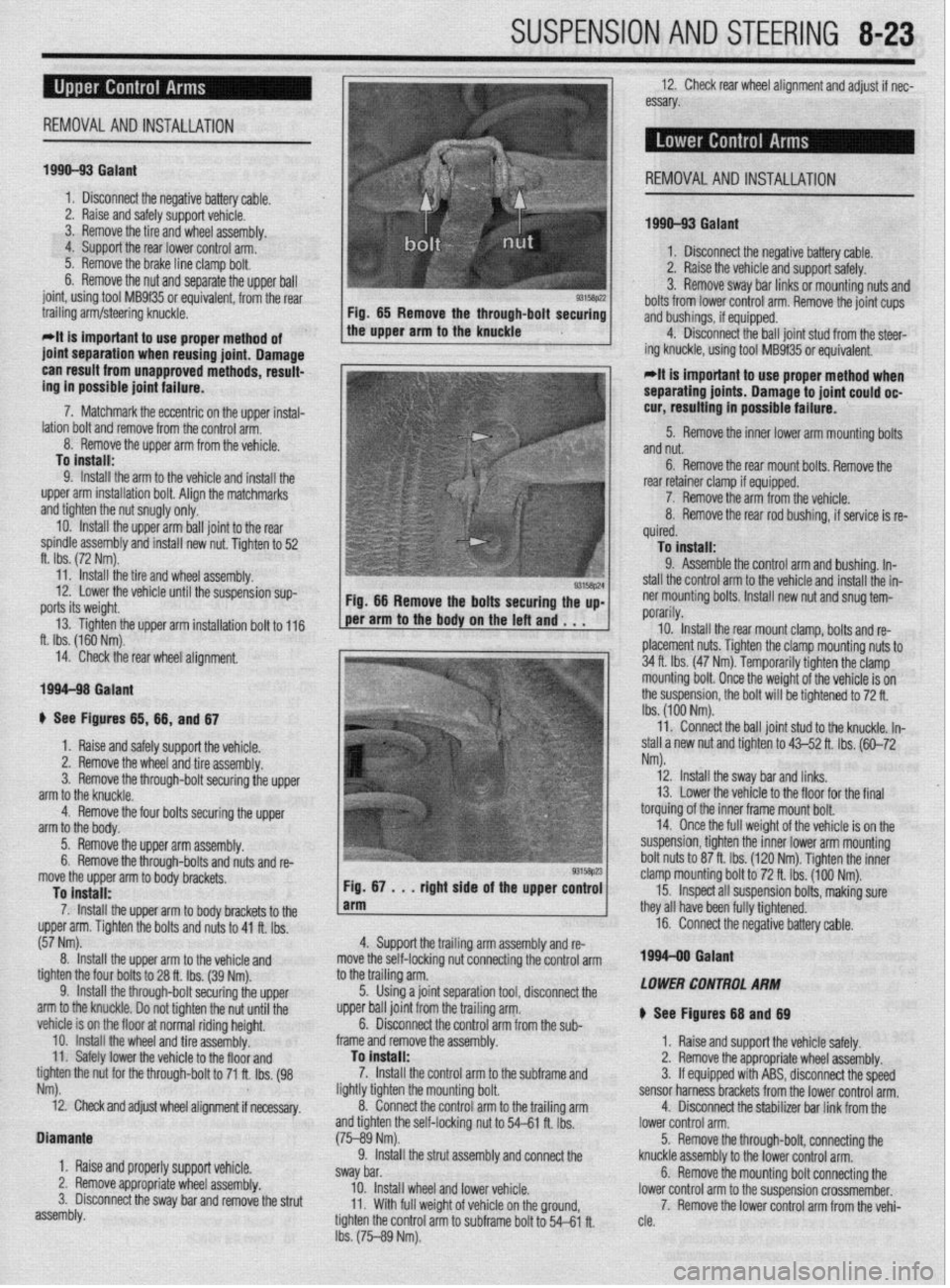
ti See Figures 65, 66, and 67 1
REMOVAL AND INSTALLATION
1990-93 Galant
2. Raise the vehicle and support safely.
!4315ap22 3. Remove sway bar links or mounting nuts and
Fig. 65 Remove the through-bolt securing bolts from lower control arm. Remove the joint cups
the upper arm to the knuckle and bushings, if equipped.
4. Disconnect the ball joint stud from the steer-
ing knuckle, using tool MB9f35 or equivalent.
*It is important to use proper method when
separating joints. Damage to joint could oc-
cur, resulting in possible failure.
5. Remove the inner lower arm mounting bolts
and nut.
6. Remove the rear mount bolts. Remove the
rear retainer clamp if equipped.
7. Remove the arm from the vehicle.
8. Remove the rear rod bushing, if service is re-
quired.
To install:
9. Assemble the control arm and bushing. In-
stall the control arm to the vehicle and install the in-
ner mounting bolts. Install new nut and snug tem-
nnrarilv md . . . 1 f.r”‘Y”‘,.
10. Install the rear mount clamp, bolts and re-
placement nuts. Tighten the clamp mounting nuts to
34 ft. Ibs. (47 Nm). Temporarily tighten the clamp
mounting bolt. Once the weight of the vehicle is on
the suspension, the bolt will be tightened to 72 ft.
Ibs. (100 Nm).
4. Support the trailing arm assembly and re-
move the Self-locking nut connecting the control arm
.* 11. Connect the ball joint stud to the knuckle. In-
stall a new nut and tighten to 43-52 ft. Ibs. (60-72
Nm).
12. Install the swav bar and links.
to tne tramng arm.
5. Using a joint separation tool, disconnect the
upper ball joint from the trailing ary.
6. Disconnect the control arm from the sub-
frame and remove the assembly.
To install:
7. Install the control arm to the subframe and
liahtlv tiahten the mounting bolt.
rol arm to the trailina arm 13. Lower the vehicle to the floor for the final
torquing of the inner frame mount bolt.
14. Once the full weight of the vehicle is on the
suspension, tighten the inner lower arm mounting
bolt nuts to 87 ft. Ibs. (120 Nm). Tighten the inner
clamp mounting bolt to 72 ft. Ibs. (100 Nm).
15. InSpet all suspension bolts, making sure
they all have been fully tightened.
16. Connect the negative battery cable.
199440 Gafant
LOWER CONTROL ARM
+ See Figures 68 and 69
1. Raise and support the vehicle safely.
2. Remove the appropriate wheel assembly.
3. If equipped with ABS, disconnect the speed
sensor harness brackets from the lower control arm.
4. Disconnect the stabilizer bar link from the
----“‘-‘I’
1 b Raise and safely support the vehicle.
2. Remove the wheel and tire assembly.
3. Remove the through-bolt securing the upper
arm to the knuckle.
4. Remove the four bolts securing the upper
arm to the body.
5. Remove the uooer arm assemhlv
re-
move the upper arm to body brackets,
To install:
7. Install the upper arm to body brackets to the
upper arm. Tighten the bolts and nuts to 41 ft. Ibs.
(57 Nm).
8. Install the upper arm to the vehicle and
tighten the four bolts to 28 ft. Ibs. (39 Nm). 6. Remove the through-bolts and nuts and
9. Install the through-bolt securing
vehicle is on the floor at normal ridina heiaht.
10. Install the wheel and tire assekbly:
11. Safely lower the vehicle to the floor and
tighten the nut for the through-bolt to 71 ft. Ibs. (98
Nm).
i2. Check and adjust wheel alignment if necessary. 8’. eonnectthe&i
and tighten the self-locki
(75-89 Nm). ng nut to 54-61 ft. Ibs.
connect the lower control arm.
5. Remove the through-bolt, connecting the
knuckle assembly to the lower control arm.
fi Romn\fn +hn mwntinn hnlt cnnnwtinn the 9. Install the strut assembly and
sway bar.
10. Install wheel and lower vehicle. V. IIVIII”“~ OK, ill” -...... J I”.. --....--.... J .,,” lower control arm to the suspension crossmember. Diamante
1, Raise and properly support vehicle.
2. Remove appropriate wheel assembly.
3. Disconnect the sway bar and remove the strut
assembly. 11. With full weight of vehicle on the ground,
tighten the control arm to subframe bolt to 54-61 ft.
Ibs. (75-89 Nm). 7. Remove the lower control arm from the vehi-
cle.
Page 319 of 408
8-24 SUSPENSION AND STEERING
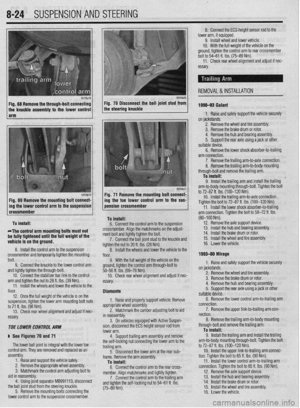
9315t$M 93158p26 Fig. 68 Remove the through-bolt connecting Fig. 70 Disconnect the ball joint stud from
the knuckle assembly to the lower control the steering knuckle
1 arm
Fig. 71 Remove the mounting bolt connect-
Fig, 89 Remove the mounting bolt connect- /
1 ing the toe lower control arm to the SW
Dolt. 9; Connect the knuckle to the lower control arm 9. With the full weigh
ground, tighten the control
and lightly tighten the through-bolt.
10. Connect the stabilizer bar link to the control
arm and tighten the nut to 28 ft. Ibs. (39 Nm).
11. Install the wheels and lower the vehicle to the
floor.
12. Once the full weight of the vehicle is on the
suspension, tighten the lower arm mounting bolt nuts
to 71 ft. Ibs. (98 Nm).
13. Check rear wheel alignment and adjust if nec-
essary.
TOE LOWER CONTROL ARhl
ti See Figures 70 and 71
The lower ball joint is integral with the lower toe
control arm. They are removed and replaced as an
assembly.
1. Raise and support the vehicle safely.
2. Remove the appropriate wheel assembly.
3. Matchmark the control arm adjusting bolt to
aid in reassembly.
4. Using joint separator MB991113, disconnect
the ball joint stud from the steering knuckle.
5. Remove the mounting bolts connecting the
lower control arm to the suspension crossmember. %--56 ft. ibs. (
10. Check
essay. rem an0 aajusr
II nec-
orl vehicle Remove
ldiustina bolt to aid
soen- Diamante
1, Raise and properly supp
appropriate whl
eel assembly.
2. Matchn
narkthe camber a , _
in reassembly.
3. On vehicles equipped with Active Su r
sion, disconnect the ECS height sensor rod from
lower arm.
4. Support trailing arm assembly and remove
the self-locking nut connecting the lower arm to the
trailing arm.
5. Disconnect the lower arm at the rear sub-
frame. Remove the arm assembly.
To install:
6. Connect the control arm to the rear cross-
member. Alion matchmarks and liahtlv tiohten.
7. Connect the control arm tothe trailing arm
and tighten the self-locking nut to 54-P e rho I I IL IY.J.
(75-89 Nm). 8. Connect the ECS height sensor rod to the
lower arm, if equipped.
9. Install wheel and lower vehicle.
IO. With the full weight of the vehicle on the
ground, tighten the control arm to rear crossmember
bolt to 54-61 ft. Ibs. (75-89 Nm).
11,
Check rear wheel alignment and adjust if nec-
essary
1996-93 Galant
1, Raise and safely support the vehicle securely
on jackstands.
2. Remove the wheel and tire assembly.
3. Remove the brake drum or rotor.
4. Remove the hub and bearing assembly.
5.
Support the rear axle using a jack or other
suitable device.
6. Remove the lower shock absorber-to-trailing
arm connection.
7. Remove the trailing arm-to-axle connection.
REMOVAL & INSTALLATION
(80-100 Nm).
12.
Remove the axle suooort device.
on jackstands.
2. Remove the wheel and tire assembly.
3. Remove the brake drum or rotor.
4. Remove the hub and bearing assembly.
5.
Support the rear axle using a jack or other
suitable device.
6. Remove the lower control arm-to-trailing arm
connection.
7. Remove the upper link-to-trailing arm con-
nection.
8. Remove the trailing arm-to-body mounting
through-bolt and remove the trailing arm.
To install:
9.
Install the trailing arm and install the trailing
arm-to-body mounting through-bolt. Tighten the bolt
to 72-87 ft. Ibs. (100-120 Nm).
10. Install the upper link-to-trailing arm connec-
tion. Tighten the bolt to 65 ft. Ibs. (90 Nm).
11. Install the lower control arm-to-trailing arm
connection. Tighten the bolt to 65 ft. Ibs. (90 Nm).
12. Remove the axle support device.
13. Install 1 he hub and bearing assembly.
14 Install 1
. _ .he brake drum or rotor.
15.
Install the wheel and tire assembly.
16. Lower the vehicle.
Page 320 of 408
SUSPENSION AND STEERING 8-25
1994-00 Galant and 1997-00 Diamante
4. Remove the retainer bolts and the stabilizer
..- 8, Loosely in”,“,, +I?,, r+&,il;7nr kn- h.~r.l,,d” -..
1. Raise and safely support the vehicle securely he bushing.
the vehicle.
on jackstands.
7er hnr with FI wmnph Remnun (1 Alinn th
2. Remove the wheel and tire assembly.
3. Support the rear axle using a jack or other
suitable device.
4. Remove the trailing arm-to-knuckle connec-
tion,
5. Remove the trailing arm-to-body mounting
n~~““yll-““!~ (1II” fWll”“C LllG llcllllll$j a,,,,. To install:
6. Install the trailing arm and install the trailing
arm-to-body mounting through-bolt. Tighten the bolt
to 99-114 ft. Ibs. (137-157 Nm).
7. Install the trailing arm-to-knuckle connection. Dar brackets. Hemove t
5. Hold the stabilL_. __. . . _ . .._..“... ..I . .._._
the self-locking nut.
6. Once the stabilizer bar nut is removed, re-
move the joint cups and stabilizer rubber bushing.
7. Hold the stabilizer link with a wrench and re-
move the self-locking nuts. Remove the stabilizer
link.
8. Lower the jack supporting the rear axle
in a slight gap between the rear sus-
? body of the vehicle.
! the stabilizer bar.
IL_ L__ I__ _)----- .-- .-J JAI.... slightly. Mainta
pension and thf
9. Remow
10. Inspect LIIB uar 101 uamage, wear ana aereno-
ration and replace as required.
-Fe c--a-...
1 IIIJMII UK 3La”III‘w “ill “lduKm “II
“. , ,,LY,, ,,ie side locating markings on the stabi-
lizer bar, so that the marking on the bar extends ap-
proximately 0.39 inches (1Omm) from the outer edge
of the mounting bracket, on both sides.
10. With the stabilizer bar properly aligned,
tighten the mounting bracket bolts to 28 ft. Ibs. (39
Nm).
11. Connect the stabilizer links to the damper fork
andihe stabilizer bar. Tighten the locking nuts to 28
ft. Ibs. (38 Nm).
12. Lower the vehicle and connect the negative
8.. Ia
mery came.
Tighten the bolt to 85-99 ft. Ibs. (118-137 Nm).
nemove me axle suppon
9. Install the wheel and tire
10. Lower the vehicle. aewce.
assembly.
I 0 Insran: 11, Install the stabilizer bar into the vehicle. Raise
the rear axle and suspension into place.
12. Install the stabilizer link into the stabilizer ba
Ir
ADJUSTMENT anfi indc4ll 33 ft. Ibs. (45 Nm).
13. Install the ioint __-_ _.._ __
1. Raise and safely support the vehicle securely the link. Ins’
..I.,
Mlhiln hnlrii, tall a rkW self~locking n
lll~llG llUlulng the stabi” ” ’ ’ ’
wrench, tighten the self,
of the stabilizer link is v
ihe hub and bearing assembly.
5. Support the rear axle using a jack or other
suitable device.
6. Remove the lower shock absorber-to-trailing
arm connection. ocking nut. Tighten the nut to
ClrnC 2nd ?$bilizer rubber to
ut onto the link.
nzer nnK oall studs with a
-locking nut so the protrusion
within 0.354-0.433 in.
I stabilizer bar bushings,
>+nn thn hnk In -I A u (9-llmm).
14. Install the cente
brackets and bolts. Tiqt Mirage
*Never disassemble the rear hub bearing.
The wheel bearing is serviced by replace-
ment of the hub.
1. Raise and safely support the vehicle.
2. Remove the rear wheel.
3. Remove the caliper and brake disc of brake 1992-96 biamante
on IacKsranos.
2. Remove the wheel and tire assembly
3, Remove thn hralm rntnr 4. Remove1
7. Remove the stabilizer bar link-to-trailing arm
connection.
8. Remove the tie rod end-to-trailing arm con-
nection.
9. Remove the lower control arm-to-trailing arm
connection.
10. Remove the trailing arm-to-body mounting
through-bolt and remove the trailing arm. Nm).
15. Install the parking
sensor installation bolt.
, , I oraxe cat * ale ar
member bracket and tighten
i Nm). Tighten the crossmem-
A to 94 ft. Ibs. (130 Nm). 16. Install the cross
the bolt to 61 ft. Ibs. (8!
ber bracket mounting nl
17. Install the rubbe
locking nuts onto the cro:
the nuts to 80-94 fl. Ibs. (
18. Lower the vehicle. id rear speed drum.
4. Remove the dust cab and tighten the flange ll”, *lb+ to 130 ft. Ibs. (180 Nm).
5. Using a dial indicator, measure wheel bear-
!r insulators and new seif-
ismemoer ’ brackets. Tighten
[110-130 Nm). ing end-play. The maximum limit for end-play is
o.oc-- ‘^ -- rzu mcnes (u.usmm).
arol
tanc
sisk 6. Using a spring scale and a rope wrapped
md the bolts, measure the rotary sliding resis-
e of the bearing/hub. The maximum limit for re-
mce is 4 Ibs. (19 N).
7. If any of the readings exceed the specifica-
To install:
11. Install the trailing arm and install the trailina Diamante and 1994-98 Gal&i
t tions, replacement of the hub is required.
8. Install the dust cap.
9. Install the brake disc and caliper, or brake
negative battery ( sble.
;“I,-.
I support the vbhlblG.
stabilizer links by removing
Alizer bar mounting brackets
from the vehicle.
lonents for wear or damage,
ded. drum.
10. Install the rear wheel assembly and lower the
vehicle to the floor.
*
1990-93 Galant
*Vehicles equipped with rear disc brakes
use a sealed hub and bearing assembly,
which requires no adjustment. Drum brake
models are
adjusted using the following pro- arm-to-body mounting through-bolt. Tighten the bolt
to 101-116 ft. Ibs. (140-160 Nm). ) See Figure 72
12. Install the trailing arm-to-lower control arm
1. Disconnect the I
connection. Tighten the bolt to 101-116 ft. Ibs.
(140-160 Nm). 2. Raise and safely
13. Install the tie rod end-to-trailing arm connec- 3. Disconnect the I
tion. Tighten the nut to 21 ft. Ibs. (29 Nm). the self-locking nuts.
14. Install the stabilizer bar link-to-trailing arm 4. Remove the stat
connection. Tighten the nut to 29 ft. Ibs. (40 Nm). and bushings.
15. Install the lower shock absorber-to-trailing
5. Remove the bar
arm connection. Tighten the bolt to 65 ft. Ibs. (90 6. Inspect all comr
. and replace parts as nee
Nrn).
16. Remove the axle support device.
17. Install the hub and bkaring assembly,
18. Install the brake rotor.
19. Install the wheel and tire assembly.
20. Lower the vehicle.
REMOVALANDINSTALLATION
1990-93 Gaiant
1. Raise and support the vehicle safely.
2. Place a jack under the rear axle and suspen- To install:
7 InstA the dnhili cedure. ._._ . . .._ -.--.. lzer bar into the vehicle.
1. Raise the vehicle and support it safely.
2. Remove the wheel and tire assemblies.
3. If equipped with rear disc brakes, remove the
caliper assembly.
4. Remove the grease cap and the hub nut.
5. Tighten the wheel bearing nut to 20 ft. Ibs. (27
Nm) while rotatir ” ”
6. Back off th
load and then tighten it to 7 ft. Ibs. (10 Nm).
7. Install the nut lock and a new cotter pin.
8. If brake caliper was removed, reinstall.
9. Install the wheel and lower the vehicle.
Diamante and lQQ44 Galant 10 tne mum/hub.
ie adjusting nut to remove the pre-
Sian assembly.
3. Remove the self-locking nuts and crossmem-
ber bracket.
93158P61 Fig. 72 Remove the self-locking nuts from Measure the wheel bearing end-play using a dial
the stabilizer bar link indicator. The end-play should be 0.002 inches
a (0.05mm) or less with the wheel bearing locknut