MITSUBISHI ECLIPSE 1990 Service Manual
Manufacturer: MITSUBISHI, Model Year: 1990, Model line: ECLIPSE, Model: MITSUBISHI ECLIPSE 1990Pages: 391, PDF Size: 15.27 MB
Page 341 of 391
23-24BODY - Power Windows / Bumpers
Batterv
r--+----
02’
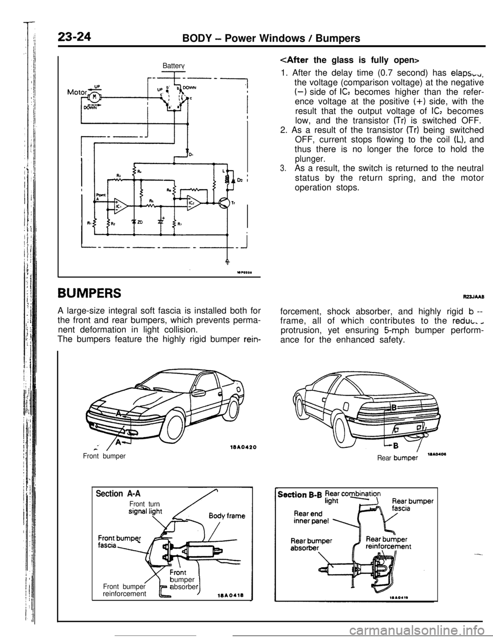
BUMPERSA large-size integral soft fascia is installed both for
the front and rear bumpers, which prevents perma-
nent deformation in light collision.
The bumpers feature the highly rigid bumper
rein-
18A0420
Section A-A
Front turn Front bumper
/Front bumperbumper
t Jabsorber
reinforcement18AOllB
1. After the delay time (0.7 second) has
claps,+,,,the voltage (comparison voltage) at the negative
(-1 side of IC2 becomes higher than the refer-
ence voltage at the positive
(+) side, with the
result that the output voltage of
ICI becomes
low, and the transistor
(Tr) is switched OFF.
2. As a result of the transistor
(Tr) being switched
OFF, current stops flowing to the coil
(L), and
thus there is no longer the force to hold the
plunger.
3.As a result, the switch is returned to the neutral
status by the return spring, and the motor
operation stops.
R22JMBforcement, shock absorber, and highly rigid
b --
frame, all of which contributes to the reduL.
aprotrusion, yet ensuring
5-mph bumper perform-
ance for the enhanced safety.
Rear bumpe:,.AOIOI
-
Page 342 of 391
CUNROOF
Page 343 of 391
23-26BODY - Sunroof
Roof lid glassSection A-ARoof lid glass
Hinge female
mm?44Section B-B
Roof lid glassSection C-CRoof lid glass
/
-mAO74E
-
Page 344 of 391
BODY- Door Mirrors .23-27
DOOR MIRRORSIPIKhAC
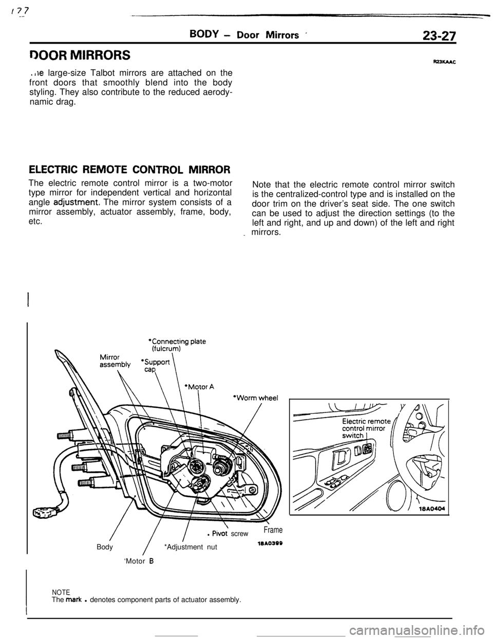
.i~e large-size Talbot mirrors are attached on the
front doors that smoothly blend into the body
styling. They also contribute to the reduced aerody-
namic drag.
ELECTRIC REMOTE CONTROL MIRRORThe electric remote control mirror is a two-motor
type mirror for independent vertical and horizontalNote that the electric remote control mirror switch
angle
adjustment The mirror system consists of ais the centralized-control type and is installed on the
mirror assembly, actuator assembly, frame, body,door trim on the driver’s seat side. The one switch
etc.can be used to adjust the direction settings (to the
left and right, and up and down) of the left and right
_ mirrors.
/
/
l Pivo; screwFrameBody*Adjustment nutleAo398
‘Motor
B
NOTE
IThe &ark l denotes component parts of actuator assembly.
I
Page 345 of 391
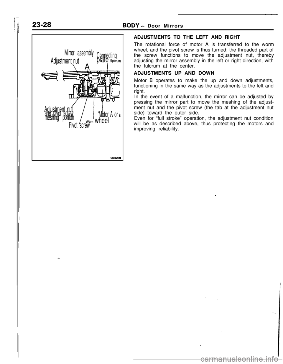
Mirror assemblywheel, and the pivot screw is thus turned; the threaded part of
Adjustment nut
\A
Connectingthe screw functions to move the adjustment nut, therebyplate (fylcrum
Iadjusting the mirror assembly in the left or right direction, with
the fulcrum at the center.
23-28---BODY - Door Mirrors
ADJUSTMENTS TO THE LEFT AND RIGHT
The rotational force of motor A is transferred to the worm
Adjustment nutand pivot screwI
meshing portionI ’‘Motor A or
B
Worm wheel
Pivot screwADJUSTMENTS UP AND DOWN
Motor
B operates to make the up and down adjustments,
functioning in the same way as the adjustments to the left and
right.In the event of a malfunction, the mirror can be adjusted by
pressing the mirror part to move the meshing of the adjust-
ment nut and the pivot screw (the tab at the adjustment nut
side) toward the outer side.
Even for “full stroke” operation, the adjustment nut condition
will be as described above, thus protecting the motors and
improving reliability.
c
Page 346 of 391
BODY - Instrument Panel / Floor Console23-29
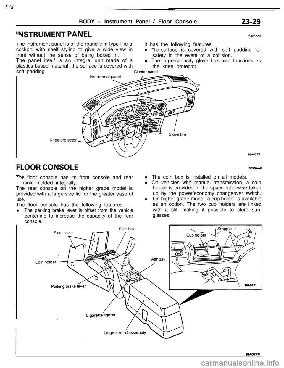
“WTRUMENT PANELR23PAA9I ne instrument panel is of the round trim type like a
cockpit, with shelf styling to give a wide view inIt has the following features.
front without the sense of being boxed in.l The surface is covered with soft padding for
The panel itself is an integral unit made of asafety in the event of a collision.
plastics-based material; the surface is covered withl The large-capacity glove box also functions as
soft padding.the knee protector.
Cluster
Dane1Knee protector
IlQAQ217
FLOOR CONSOLE
rhe floor console has its front console and rear
nsole molded integrally.
The rear console on the higher grade model is
provided with a large-size lid for the greater ease of
use.The floor console has the following features.
lThe parking brake lever is offset from the vehiclecenterline to increase the capacity of the rear
R23clAABl The coin box is installed on all models.
l On vehicles with manual transmission, a coin
holder is provided in the space otherwise taken
up by the power/economy changeover switch.
lOn higher grade model, a cup holder is available
as an option. The two cup holders are linked
with a slit, making it possible to store
sun-
glasses.
console.
Side coverCoin box/
/\ lQAO27l
Page 347 of 391
23-30
FRONT SEATS
BODY - Front Seats / Rear Seat
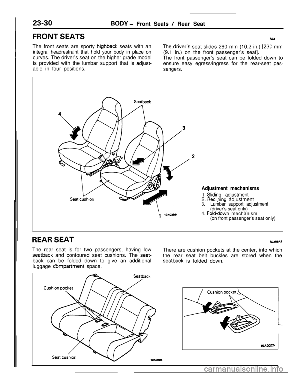
Rz3The front seats are sporty
highback seats with an
integral headrestraint that hold your body in place oncurves. The driver’s seat on the higher grade model
is provided with the lumbar support that is
adjust-able in four positions.The.driver’s seat slides 260 mm (10.2 in.) I230 mm
(9.1 in.) on the front passenger’s seat].
The front passenger’s seat can be folded down to
ensure easy egress/ingress for the rear-seat pas-
sengers.
Seatback
2
Adjustment mechanisms
1. Sliding adjustment2. Reclining adjustment3.Lumbar support adjustment(driver’s seat only)
4.
Folddown mechanism
(on front passenger’s seat only)
REAR SEATR23u9ABThe rear seat is for two passengers, having low
seatback and contoured seat cushions. The seat-back can be folded down to give an additional
luggage c5mpartment space.There are cushion pockets at the center, into which
the rear seat belt buckles are stored when the
seatback is folded down.
Page 348 of 391
BODY - Seat Belts
._-- -
23-31
Shoulder beltI
Lapbelt
IGlove box pad toasty
Knee protector
Guide rail\Fasten switch
\
SEAT BELTSRZ3SBAS
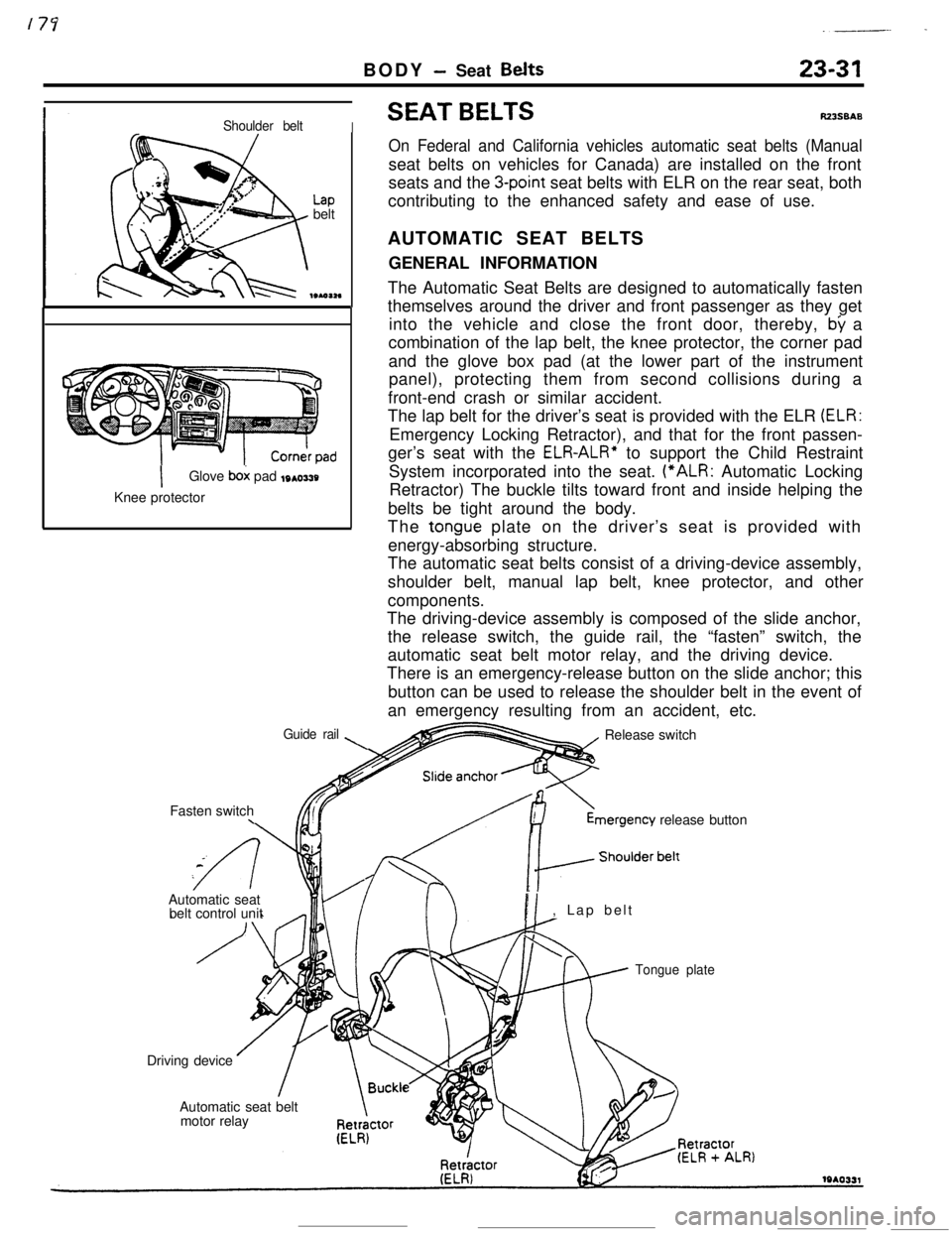
On Federal and California vehicles automatic seat belts (Manualseat belts on vehicles for Canada) are installed on the front
seats and the
3-point seat belts with ELR on the rear seat, both
contributing to the enhanced safety and ease of use.
AUTOMATIC SEAT BELTS
GENERAL INFORMATION
The Automatic Seat Belts are designed to automatically fasten
themselves around the driver and front passenger as they get
into the vehicle and close the front door, thereby,
by a
combination of the lap belt, the knee protector, the corner pad
and the glove box pad (at the lower part of the instrument
panel), protecting them from second collisions during a
front-end crash or similar accident.
The lap belt for the driver’s seat is provided with the ELR
(ELR:Emergency Locking Retractor), and that for the front passen-
ger’s seat with the
ELR-ALR” to support the Child Restraint
System incorporated into the seat. (“ALR: Automatic Locking
Retractor) The buckle tilts toward front and inside helping the
belts be tight around the body.
The
tongue plate on the driver’s seat is provided with
energy-absorbing structure.
The automatic seat belts consist of a driving-device assembly,
shoulder belt, manual lap belt, knee protector, and other
components.
The driving-device assembly is composed of the slide anchor,
the release switch, the guide rail, the “fasten” switch, the
automatic seat belt motor relay, and the driving device.
There is an emergency-release button on the slide anchor; this
button can be used to release the shoulder belt in the event of
an emergency resulting from an accident, etc.
Release switchmergency
release button
Automatic seat
belt control unit
PI, Lap belt
Tongue plateDriving device
Automatic seat belt
motor relay
Page 349 of 391
23-32BODY - Seat Belts
OPERATION OF AUTOMATIC SEAT BELTS
The operation of the Automatic Seat Belts is as follows.
(1) The belts fasten itself around the occupant when the front
door is closed with the ignition switch in the “ON” position.
(2) The belts release itself from the occupant when the front
door is opened with the ignition switch in the
*“ON” or
“LOCK” or “ACC” position.
(3) The belts cease to fasten itself around the occupant if the
ignition switch is turned to “LOCK” or “ACC” or when the
front door is opened during the belt motion.
(4) The belts for the driver’s and front passenger’s seats
operate independently of each other.
Lever springStopper, Rod A
Sub paw1
Gear B
Rod B19po37:
Sub’pawlIWO374
IStopperGear AI
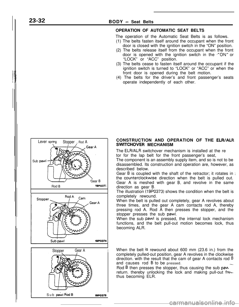
ISub pai.4 dodB1980376CONSTRUCTION AND OPERATION OF THE
ELR/ALR,
SWITCHOVER MECHANISM
The
ELR/ALR switchover mechanism is installed at the re
tor for the lap belt for the front passenger’s seat,
The component is an assembly supply item, and so is not to be
disassembled. Its construction and operation are, however, as
described below.
Gear
B is coupled with the shaft of the retractor; it rotates in ::the counterclockwise direction when the belt is pulled out.
Gear A is meshed with gear
B, and revolve in the same
direction as gear
B.The illustration
(19PO373) shows the condition when the belt is
completely rewound.
When the belt is pulled out completely, gear A revolves about
three times, and the gear A cam contacts rod A, thereby
pressing rod A. Rod A then presses the stopper, and the
stopper presses the sub
pawl.When the sub pawl is pressed, the internal lock mechanism
functions, and the belt pull-out motion becomes lock, thus
becoming ALR.
When the belt
is rewound about 600 mm (23.6 in.) from the
completely pulled-out position, gear A revolves in the clockwise
direction. with the result that the cam of gear A contacts rod
6and causes rod
B to be pressed.
Rod
B then presses the stopper, thus causing the sub pan -return. thereby unlocking the lock and making pull-out
freti.thus becoming ELR.
Page 350 of 391
BODY - Seat Belts23-33
Gear eGear B
Energy-absorbingbelt
Before absorbing
shock
19AO332Inward
Forward
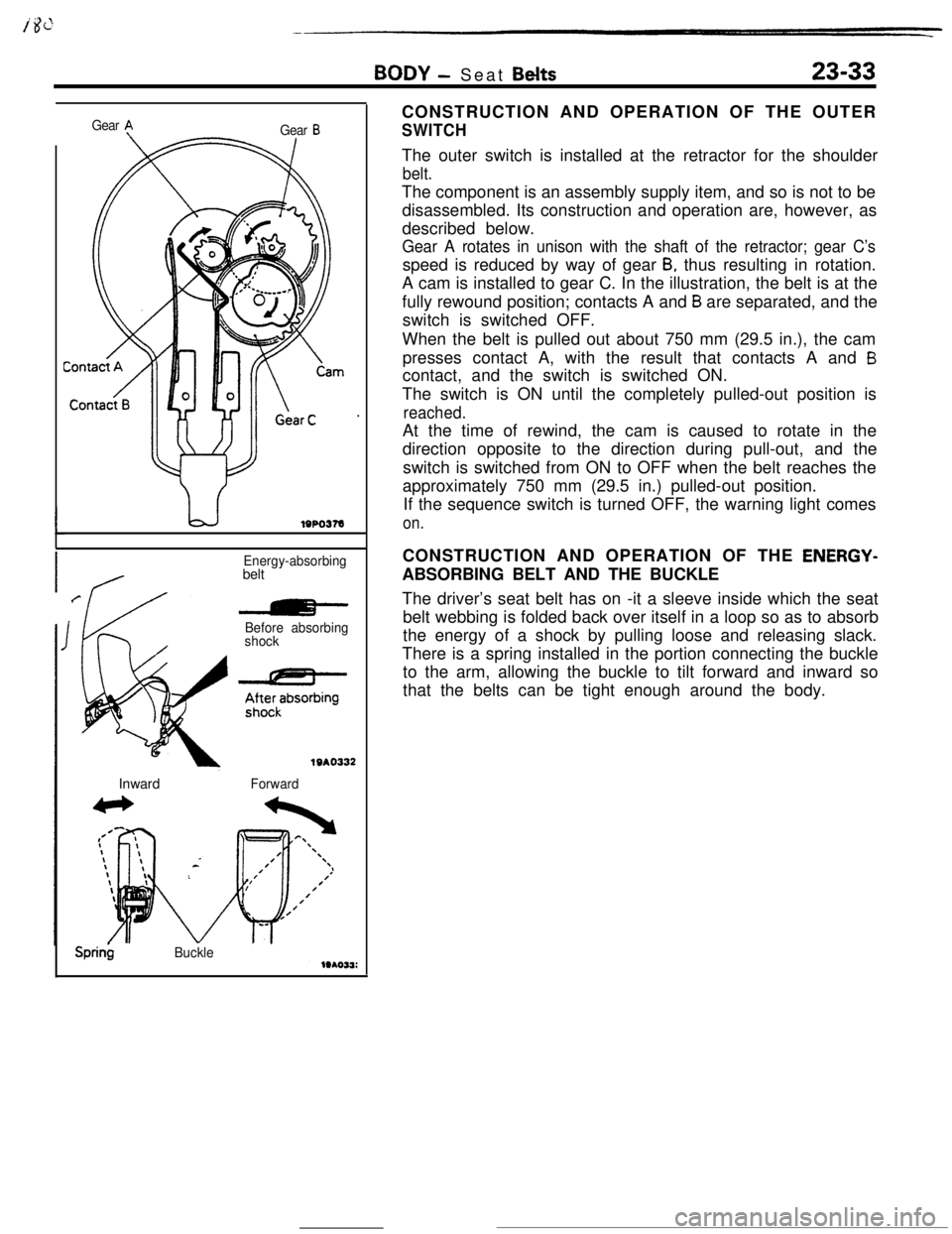
Sprin$BuckleCONSTRUCTION AND OPERATION OF THE OUTER
SWITCHThe outer switch is installed at the retractor for the shoulder
belt.The component is an assembly supply item, and so is not to be
disassembled. Its construction and operation are, however, as
described below.
Gear A rotates in unison with the shaft of the retractor; gear C’sspeed is reduced by way of gear
B, thus resulting in rotation.
A cam is installed to gear C. In the illustration, the belt is at the
fully rewound position; contacts A and
B are separated, and the
switch is switched OFF.
When the belt is pulled out about 750 mm (29.5 in.), the cam
presses contact A, with the result that contacts A and
Bcontact, and the switch is switched ON.
The switch is ON until the completely pulled-out position is
reached.At the time of rewind, the cam is caused to rotate in the
direction opposite to the direction during pull-out, and the
switch is switched from ON to OFF when the belt reaches the
approximately 750 mm (29.5 in.) pulled-out position.
If the sequence switch is turned OFF, the warning light comes
on.CONSTRUCTION AND OPERATION OF THE
ENERGY-ABSORBING BELT AND THE BUCKLE
The driver’s seat belt has on -it a sleeve inside which the seat
belt webbing is folded back over itself in a loop so as to absorb
the energy of a shock by pulling loose and releasing slack.
There is a spring installed in the portion connecting the buckle
to the arm, allowing the buckle to tilt forward and inward so
that the belts can be tight enough around the body.