MITSUBISHI ECLIPSE 1990 Service Manual
Manufacturer: MITSUBISHI, Model Year: 1990, Model line: ECLIPSE, Model: MITSUBISHI ECLIPSE 1990Pages: 391, PDF Size: 15.27 MB
Page 361 of 391
23-44BODY -Seat Belts
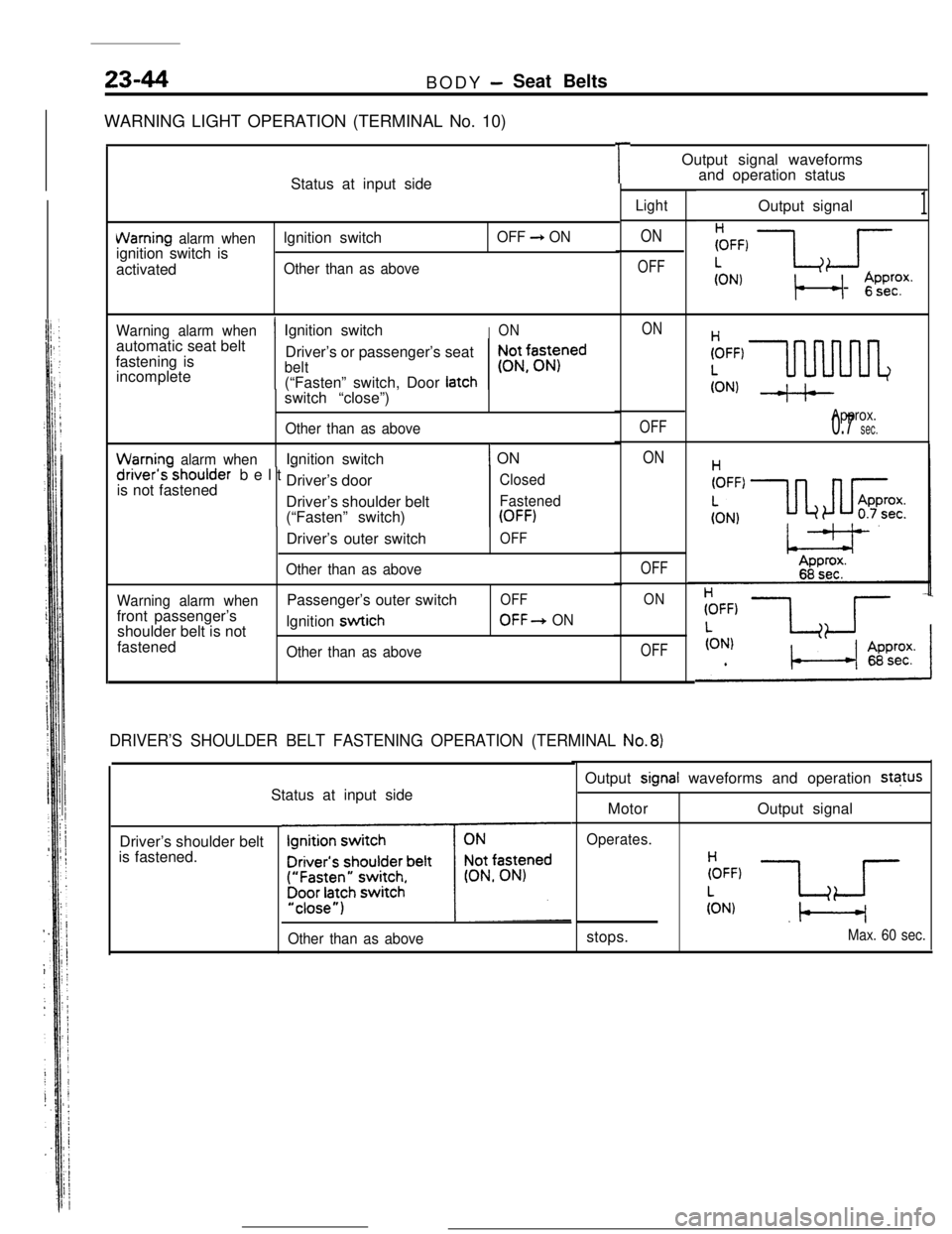
WARNING LIGHT OPERATION (TERMINAL No. 10)
Status at input side
VVarning alarm whenlgnition switchOFF 3 ONignition switch is
activated
Other than as above
Warning alarm whenautomatic seat belt
fastening is
incomplete
1 Ignition switch
Driver’s or passenger’s seatION
belt
r;tNfasyed
’(“Fasten” switch, Door latchswitch “close”)
Other than as above
Warninn alarm whenIgnition switch1 ONdriver’sshoulder belt -
is not fastenedDriver’s door
Driver’s shoulder belt
(“Fasten” switch)
Closed
Fastened
(OFF)Driver’s outer switch
Other than as above
OFF
Warning alarm whenfront passenger’s
shoulder belt is not
fastenedPassenger’s outer switch
lgnition
swtich
Other than as above
OFF
OFF+ ON
r
Light
ON
OFF
ON
OFF
ON
OFF
ON
OFF
DRIVER’S SHOULDER BELT FASTENING OPERATION (TERMINAL No.8)Status at input side
Driver’s shoulder belt
is fastened.
‘~
Other than as aboveOutput signal waveforms
and operation status
Output signalFFF,
LJ
(ON)t, +j ‘$;P$
Approx.0.7 sec.
1Output
signal waveforms and operation status
MotorOutput signal
Operates.stops.
(ON).l---l
Max. 60 sec.
Page 362 of 391
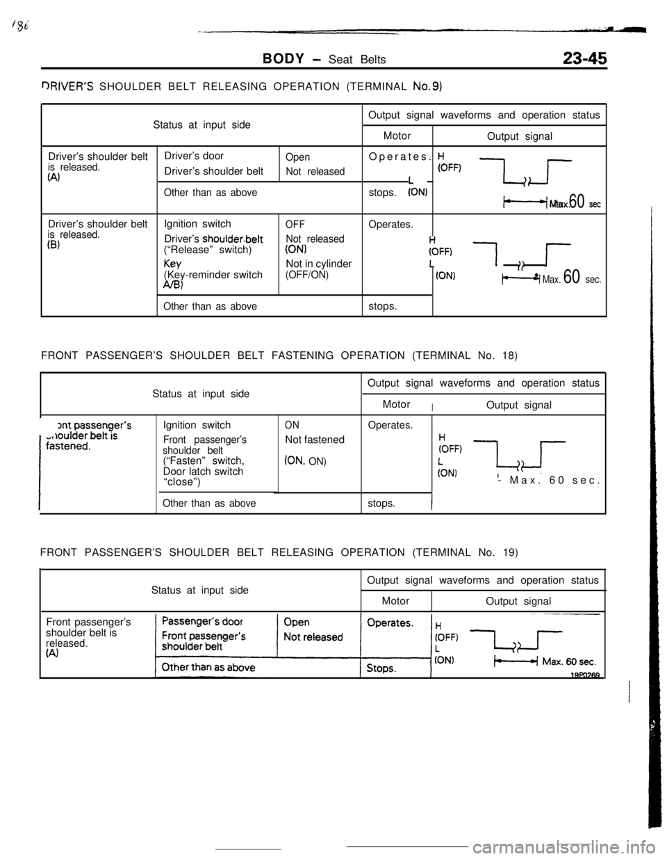
BODY - Seat Belts23-45QRIVER’S SHOULDER BELT RELEASING OPERATION (TERMINAL
No.9)Status at input sideOutput signal waveforms and operation status
Motor
Output signal
Driver’s shoulder beltDriver’s door
is released.OpenOperates. H
(A)Driver’s shoulder beltNot released(OFF)
Other than as abovestops.:ONl -$<
Max. 60 setDriver’s shoulder beltlgnition switch
OFFis released.Operates.
03)Driver’s shoulder.beltNot released(“Release” switch)
(ON)
Key(Key-reminder switchNot in cylinder(OFF/ON)FFF)
1 ;: r
A/B)(ON1p-9 Max. 60 sec.
Other than as abovestops.
FRONT PASSENGER’S SHOULDER BELT FASTENING OPERATION (TERMINAL No. 18)
Status at input side
Ignition switch
Front passenger’s
shoulder belt(“Fasten” switch,
Door latch switch
“close”)
Other than as above
ONNot fastened
(ON, ON)Output signal waveforms and operation status
Motor
IOutput signal
Operates.- Max. 60 sec.
stops.
IFRONT PASSENGER’S SHOULDER BELT RELEASING OPERATION (TERMINAL No. 19)
Status at input sideOutput signal waveforms and operation status
Motor
Output signal
Front passenger’s
shoulder belt is
released.(A)
Page 363 of 391
23-46REAR SEAT BELTBODY - Seat Belts
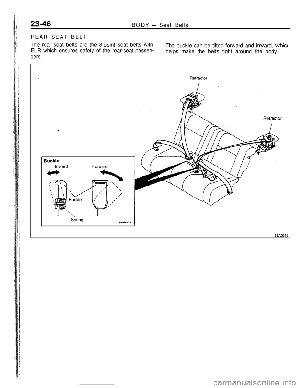
The rear seat belts are the
3-point seat belts with
ELR which ensures safety of the rear-seat
passen-
gers.The buckle can be tilted forward and inward, whicn
helps make the belts tight around the body.
Retractor
BuckleInward
Forward
Page 364 of 391
24-1
HEATERS
CONDITIONING
CONTENTS Rx&--
.._.........I............................... 8 HEATER CONSTRUCTIO N. . . . . . . . .._..................... 5
Compressor Control . . . . . . . . . . . . . . . . . . . . . . . . . . . . _ . . . . . . .._.. 8IDLE SPEED CONTRO L. . . . . . . . . . . . . . . . . . . . . . . . . . . . . . . . . . . . \
. . . . 9
tNFORMATt0N. . . . . . .._................_......2
Page 365 of 391
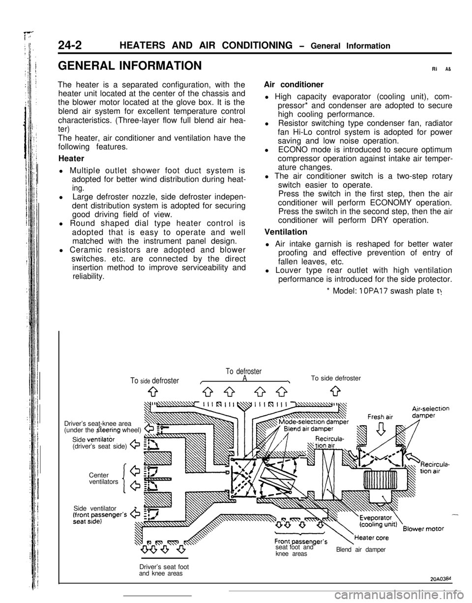
24-2 HEATERS AND AIR CONDITIONING
1 OPA17 swash plate t:
To defroster
/A\To side defroster
9G-3 53033
ventilators
‘lo’
Driver’s seat-knee area3$
(under the fieering wheel)b
Side ventilatbr(driver’s seat side) G
Center
20A03M
Page 366 of 391
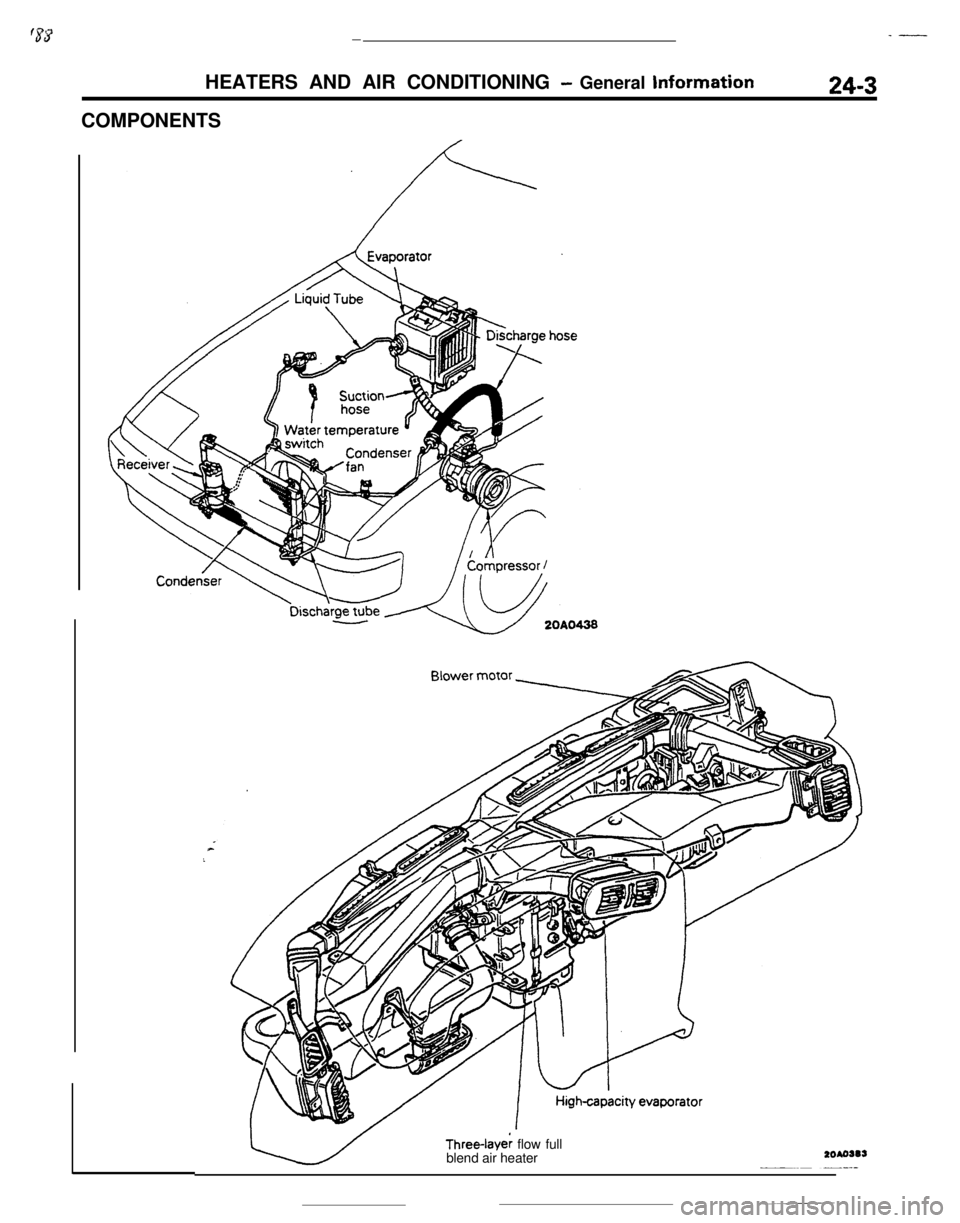
_-‘5sY-HEATERS AND AIR CONDITIONING
- General Information
COMPONENTS24-3Three-Iaye; flow full
blend air heater
Page 367 of 391
L.
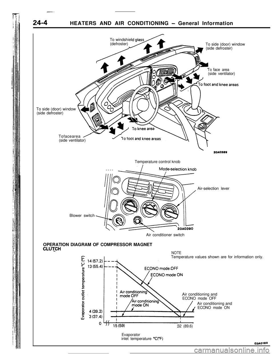
24-4HEATERS AND AIR CONDITIONING - General Information
’ /To side (door) window
(side defroster)
t4L\ m\vTofacearea
/(side ventilator)To windshiel
(defroster)
To side (door) window
(side defroster)
Blower switch
Toface area(side ventilator)
u rorootanTemperature control knob
, , , ,Air-selection lever
Air conditioner switch
OPERATION DIAGRAM OF COMPRESSOR MAGNET
CLUTCHNOTETemperature values shown are for information only.
Air conditioning and
ECONO mode OFFAir conditioning and
ECONO mode ON
II
32 (89.6)
Evaporatorinlet temperature “WF)
Page 368 of 391
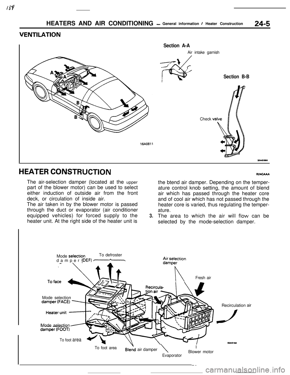
HEATERS AND AIR CONDITIONING- General information I Heater Construction24-5
16AO611
Section A-A
Air intake garnish
Check
Section B-B
HEATER CONSTRUCTIONThe air-selection damper (located at the upper
part of the blower motor) can be used to select
either induction of outside air from the front
deck, or circulation of inside air.
The air taken in by the blower motor is passed
through the duct or evaporator (air conditioner
equipped vehicles) for forced supply to the
heater unit. At the right side of the heater unit is
Mode selectionTo defroster
damper
!DEF) mMode selection
3.the btend air damper. Depending on the temper-
ature control knob setting, the amount of blend#waAA
air which has passed through the heater core
and of cool air which has not passed through the
heater core is varied, thus regulating the temper-
ature.The area to which the air will
flow can be
selected by the mode-selection damper.
nFresh airMode selection
To foot areaair damper\IEvaporatorBlower motorRecirculation
dair
To foot area+-l
Page 369 of 391
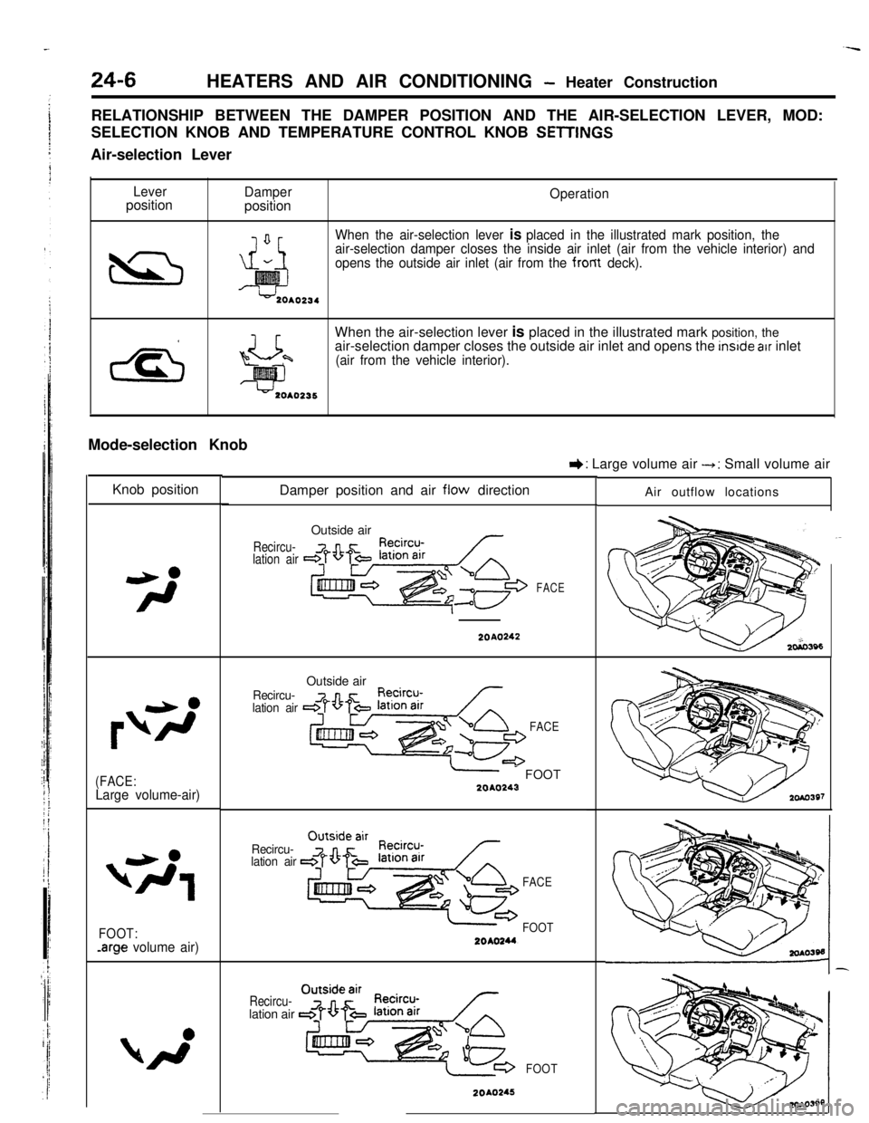
--
24-6HEATERS AND AIR CONDITIONING - Heater Construction
RELATIONSHIP BETWEEN THE DAMPER POSITION AND THE AIR-SELECTION LEVER, MOD:
SELECTION KNOB AND TEMPERATURE CONTROL KNOB
SETlINt%Air-selection Lever
LeverpositionDamperpositionOperation
When the air-selection lever
is placed in the illustrated mark position, the
air-selection damper closes the inside air inlet (air from the vehicle interior) and
opens the outside air inlet (air from the from
deck).When the air-selection lever is placed in the illustrated mark position, the
air-selection damper closes the outside air inlet and opens the
inslde atr inlet
(air from the vehicle interior).Mode-selection Knob
Knob position
(FACE:Large volume-air)
FOOT:-arge volume air)Damper position and air
flow direction
Recircu-
lation airOutside air
FACE
I): Large volume air --t: Small volume air
20A0242
Recircu-
lation airOutside air
FACE
-- FOOT2040243
Recircu-
lation air
FACE
FOOT
Recircu-lation air
FOOT
20A0245Air outflow locations
Page 370 of 391

HEATERS AND AIR CONDITIONING - Heater Construction24-7
IKnob posltionDamper position and air flow direction
Air outflow locations
Outside air
Recircu-lation air
2010246
Recircu-iation airDEF
2OAO247Temperature Control Knob
IKnob positionDamper position and air ‘flow directionOperation
When the temperature control knob or
the heater control is rotated fully
counterclockwise toward the cool air
position, the upper side of the heater
core will be blocked up by the blend
air damper A. whereas the lower side
of the heater core
will be blocked up by
the blend air damper 8. As a result.
all the air from the blower motor does
not pass through the heater core but
directly flows out as cool air.
Blend air damper CBlend air damper A
x!= cY?l-nY-/
-1 From
To air Voutflowopenings*blower
motor
Hester ‘OreOUO,,O
Blend air damper CBlend air damper A,//7When the temperature control knob of
the heater control is rotated fully
ctockwise toward the warm air position.the blend air dampers A and Bwill block the cool air paths.
The cool air from the blower motor
passes through the heater core for
maximum heating..
Tooutflow
openings
Blend al’r damper B
When the temperature control knob of
the heater control is rotated to the
mid position, the blend air dampers A
and B will split the air stream intotwo branches, one passing through the
heater core and one not passing through
the heater core. The blend damper air
Cintroduces cool air from the heater core
top into the heater unit chamber. Air
conditioning is provided by mixing this
cool air with hot air heated by the
heater cores.
Blend air damper CBlend/ air damper AL
2OAO391Blend air damoer B
--.-__.__ ,_ .