MITSUBISHI ECLIPSE 1990 Service Manual
Manufacturer: MITSUBISHI, Model Year: 1990, Model line: ECLIPSE, Model: MITSUBISHI ECLIPSE 1990Pages: 391, PDF Size: 15.27 MB
Page 371 of 391
-.-- ----_-
24-8HEATERS AND AIR CONDITIONING - Compressor
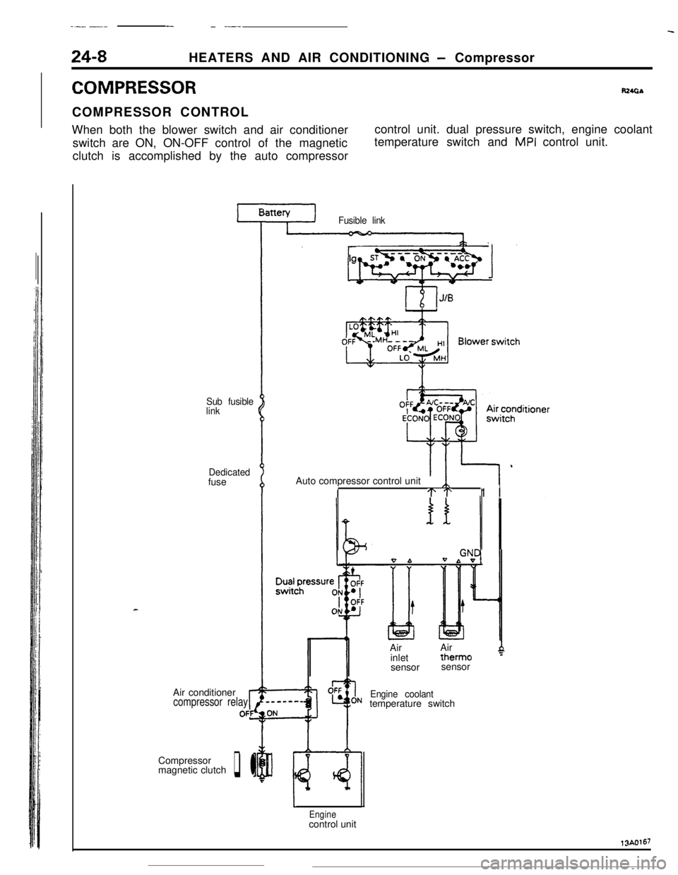
COMPRESSORR24GbCOMPRESSOR CONTROL
When both the blower switch and air conditioner
switch are ON, ON-OFF control of the magnetic
clutch is accomplished by the auto compressorcontrol unit. dual pressure switch, engine coolant
temperature switch and
MPI control unit.
Sub fusible
link
Dedicatedfuse
Air conditioner
compressor relayrOFfCompressor
magnetic clutch
q l
Fusible link
lgnitionsyhWqb 1Auto compressor control unit
ITT1 I
0 bIAirAir
inlettherm0
4sensorsensor
Engine coolanttemperature switch
Enginecontrol unit13A0167
Page 372 of 391
19/---..-_HEATERS AND AIR CONDITIONING
- Idle Speed Control24-9
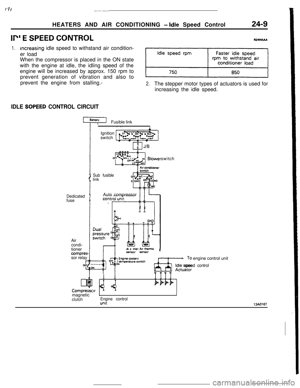
Ii” E SPEED CONTROL
1.increasing idle speed to withstand air condition-
er load
When the compressor is placed in the ON state
with the engine at idle, the idling speed of the
engine will be increased by approx. 150 rpm to
prevent generation of vibration and also to
prevent the engine from stalling.-
2.The stepper motor types of actuators is used for
increasing the idle speed.
IDLE SOPEED CONTROL CIRCUITFusible link
Dedicatedfuse
Air
condi-tioner
compressor relay
I-gcfc
Lll
Compre:Ignition
switch
Sub fusible
linkswitch
Auto compressor
As
mlef kr Ihemo
Ax;,: engine control unit
Idle speed control
Y *e:Q
1
$4.1111.Pk+F)rmagneticIJ
clutchEngine controlunit13AO167
Page 373 of 391
25-1
EMISSION
CONTROL SYSTEMSCONTENTS
RZSA---AIR-FUEL MIXTURE
RATIOCONTROL SYSTEM
. . . . . . . . . . . . . . . . . . . . . . . . .._.................9CATALYTIC CONVERTER
. . . . . . . . . . . . . . . . . .._............9CRANKCASE VENTlLATlON SYSTEM
. . . . . . . . . . . .10EVAPORATIVE EMISSION
CONTROL SYSTEM
: . . . . . . . . . . . . . . . . . . . . . . . . . . . . . . . ..-.........11Canister
. . . . . . . . . . . . . . . . . . . . . . . . . . . ..~...................._._...__..12
FuelCheck Valve. . . . . . . . . . . . . . . . . . . . . . . . . . . . . . . . . . . . .._.........14
FuelFiller Cap. . . . . . . . . . . . . . . . . . . . . . . . . . . . . . . . . . . . . . . . ..__....._..14Overfill Limiter (Two-way Valve)
_................... 14
Purge Control Solenoid Valve
. . . . . . . . . . . . . . . . . . . . . . . . . . . . . . . . . . . . . . . . . . . . . . . . . . . .13Purge Control Solenoid Valve
. . . . . . . . . . . _ . . . . . . . . . . . . . . . . . . . . . . . . . . . . . . . . . . . . . . . . . . . . . . . .13Purge Control Valve
. . . . . . . . . . . . . . . . . . . . . . . .13EXHAUST GAS RECIRCULATION
(EGR) SYSTEM. . . . . . . . . . . . . . . . . . . . . . . . . . . . . . . . . . . . . . . . . . . ..-......5
EGR Control Solenoid Valve
..,.........................................7EGR Temperature Sensor
. . . . . . . .8Operation
. . . . . . . . . . . . . . . . . . . . . . . . . . . . . . . . . . . .6
Operation
Therm0 Valve
. . . . . . . . . . . . . . . . . . . . . . . . . . . . . . . .2
Page 374 of 391
25-2EMISSION CONTROL SYSTEMS - General Information
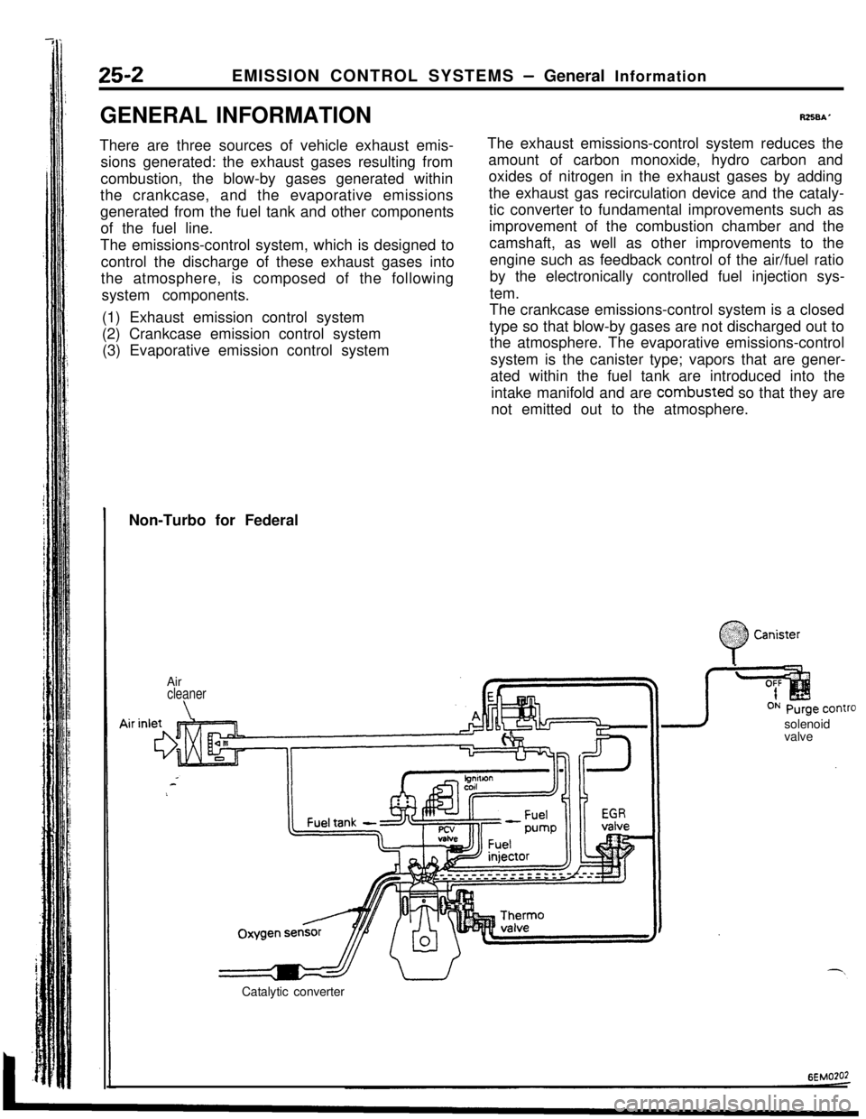
GENERAL INFORMATION
There are three sources of vehicle exhaust emis-
sions generated: the exhaust gases resulting from
combustion, the blow-by gases generated within
the crankcase, and the evaporative emissions
generated from the fuel tank and other components
of the fuel line.
The emissions-control system, which is designed to
control the discharge of these exhaust gases into
the atmosphere, is composed of the following
system components.
(1) Exhaust emission control system
(2) Crankcase emission control system
(3) Evaporative emission control system
R258A’The exhaust emissions-control system reduces the
amount of carbon monoxide, hydro carbon and
oxides of nitrogen in the exhaust gases by adding
the exhaust gas recirculation device and the cataly-
tic converter to fundamental improvements such as
improvement of the combustion chamber and the
camshaft, as well as other improvements to the
engine such as feedback control of the air/fuel ratio
by the electronically controlled fuel injection sys-
tem.
The crankcase emissions-control system is a closed
type so that blow-by gases are not discharged out to
the atmosphere. The evaporative emissions-control
system is the canister type; vapors that are gener-
ated within the fuel tank are introduced into the
intake manifold and are combusted so that they are
not emitted out to the atmosphere.
Non-Turbo for Federal
Air
cleaner
\solenoid
valve
Catalytic converter
:
0
$2:) Canister:.:
Page 375 of 391
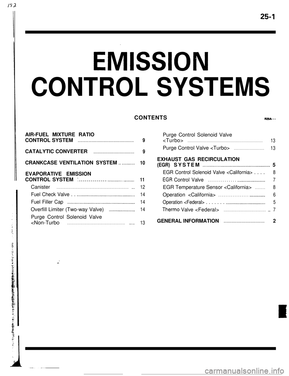
25-1
Eh/llSSlON
CONTROL SYSTEMS
rps*---
AIR-FUEL MIXTURE RATIO
_ . . . . . . . . . . . . . . . . . . . . . . . . . . . . . . . . . . .
CATALYTIC CONVERTER . . . . . . . . . . . . . . . . . . . . . . . . . . . . . . . .
._ _.__.____.
EVAPORATIVE EMISSION
: . . . . . . . . . . . . . . .._............. _ _.I.........
Canister . . . . . . . . . . . . . . . . . . . . . . . . . . . . . . . . . . . . \
. . . . . . . . . . . . . . . . . . . ..-..
Fuel Check Valve . . .._......._....._......__...._.__.............
Fuel Filler CapI.........._........................................
Overfill Limiter (Two-way Valve)_......._._.._._....
Purge Control Solenoid Valve
.._. _...
9
_..._............................................... 5
EGR Control Solenoid Valve
EGR Control Valve . . . . . . . . . . . . . . .._........................... 7
EGR Temperature Sensor
.._................ 6
Operation
Therm0 Valv e
GENERAL INFORMATIO N. . . . . . . . . . . . . . . . . . . . . . . . . . . . . . . . 2
Page 376 of 391
--.
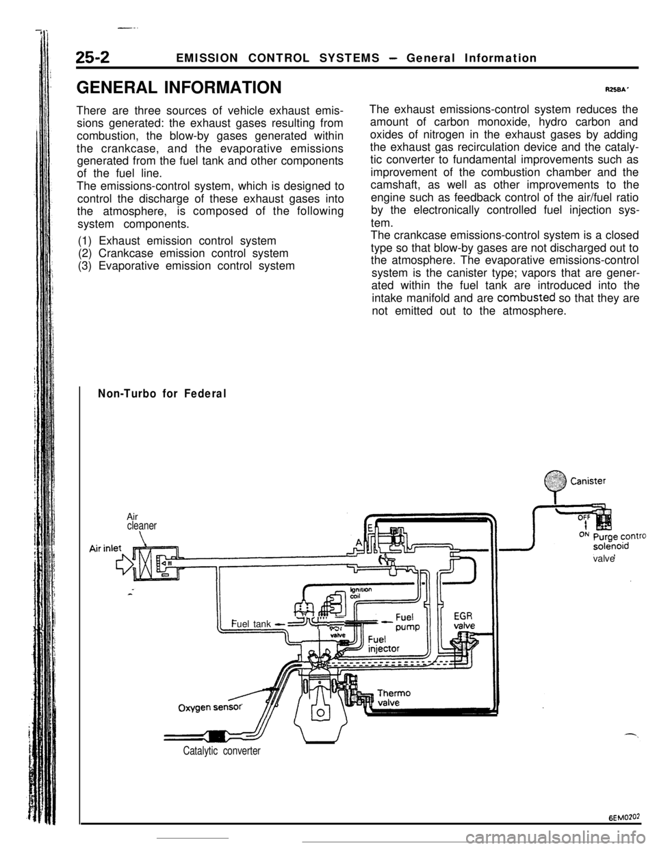
25-2EMISSION CONTROL SYSTEMS - General Information
GENERAL INFORMATION
There are three sources of vehicle exhaust emis-
sions generated: the exhaust gases resulting from
combustion, the blow-by gases generated within
the crankcase, and the evaporative emissions
generated from the fuel tank and other components
of the fuel line.
The emissions-control system, which is designed to
control the discharge of these exhaust gases into
the atmosphere,is composed of the following
system components.
(1) Exhaust emission control system
(2) Crankcase emission control system
(3) Evaporative emission control system
RZSBAThe exhaust emissions-control system reduces the
amount of carbon monoxide, hydro carbon and
oxides of nitrogen in the exhaust gases by adding
the exhaust gas recirculation device and the cataly-
tic converter to fundamental improvements such as
improvement of the combustion chamber and the
camshaft, as well as other improvements to the
engine such as feedback control of the air/fuel ratio
by the electronically controlled fuel injection sys-
tem.
The crankcase emissions-control system is a closed
type so that blow-by gases are not discharged out to
the atmosphere. The evaporative emissions-control
system is the canister type; vapors that are gener-
ated within the fuel tank are introduced into the
intake manifold and are combusted so that they are
not emitted out to the atmosphere.
Non-Turbo for Federal
.;. :
0
.%??? CanisterAir
cleaner
\valveOxygenFuel tank
-a I”’ ,T
sensr’
Catalytic converter
6EMO?O2
Page 377 of 391
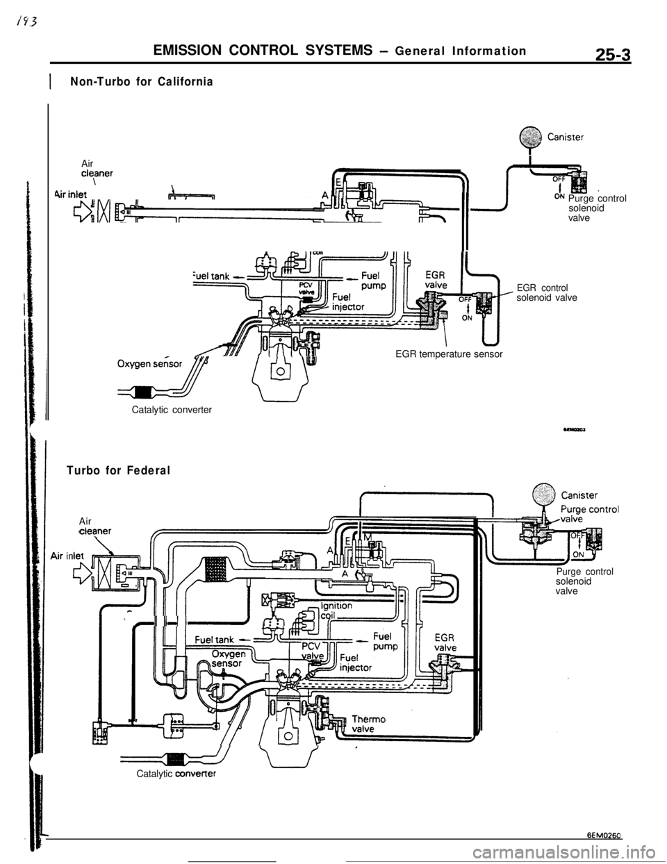
EMISSION CONTROL SYSTEMS - General Information25-3
INon-Turbo for California
Q
&i,& Canister<; /’Aircleaner\
hrinlet &j=-=&=p==~
oxz pJCatalytic converterEGR temperature sensor
ON Purge control
solenoid
valve
EGR controlsolenoid valve
Turbo for FederalAir
cleper
E
-II 11-l I-d-h I
-u’Catalytic a3nverter
in
Purge controlsolenoid
valve
6EM0260
Page 378 of 391
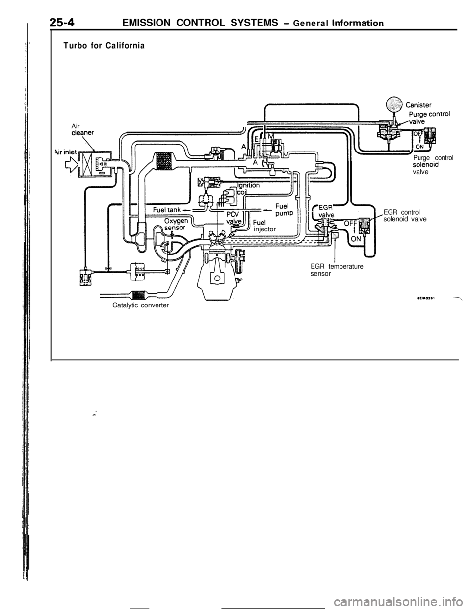
EMISSION CONTROL SYSTEMS - General Information
Turbo for CaliforniaAir
sokkoidvalvePurge control
I/ I
, ,LUII‘P
p injector
Catalytic converter
EGR temperaturesensor
t
EGR controlsolenoid valve
Page 379 of 391
‘Sv’_ -EMISSION CONTROL SYSTEMS
-Exhaust Gas Recirculation (EGR) System25-5
FYHAUST GAS RECIRCULATION
\ ,GR) SYSTEM
RZSCAAB
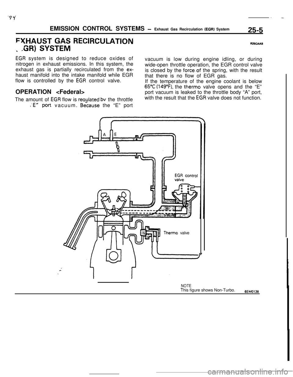
EGR system is designed to reduce oxides of
nitrogen in exhaust emissions. In this system, the
exhaust gas is partially recirculated from the
ex-haust manifold into the intake manifold while EGR
flow is controlled by the
EGR control valve.
OPERATION
The amount of
EGR flow is reaulated bv the throttlevacuum is low during engine idling, or during
wide-open throttle operation, the EGR control valve
is closed by the force.of the spring, with the result
that there is no flow of EGR gas.
If the temperature of the engine coolant is below
65°C (149”F), the therm0 valve opens and the “E”
port vacuum is leaked to the throttle body “A” port,
with the result that the
EGR valve does not function.
l ’E”Portvacuum. &cause the “E” port
Therm0 valve
NOTE-This figure shows Non-Turbo.6EM0136
Page 380 of 391
-.-
25-6EMISSION CONTROL SYSTEMS- Exhaust Gas Recirculation (EGR) System
OPERATION
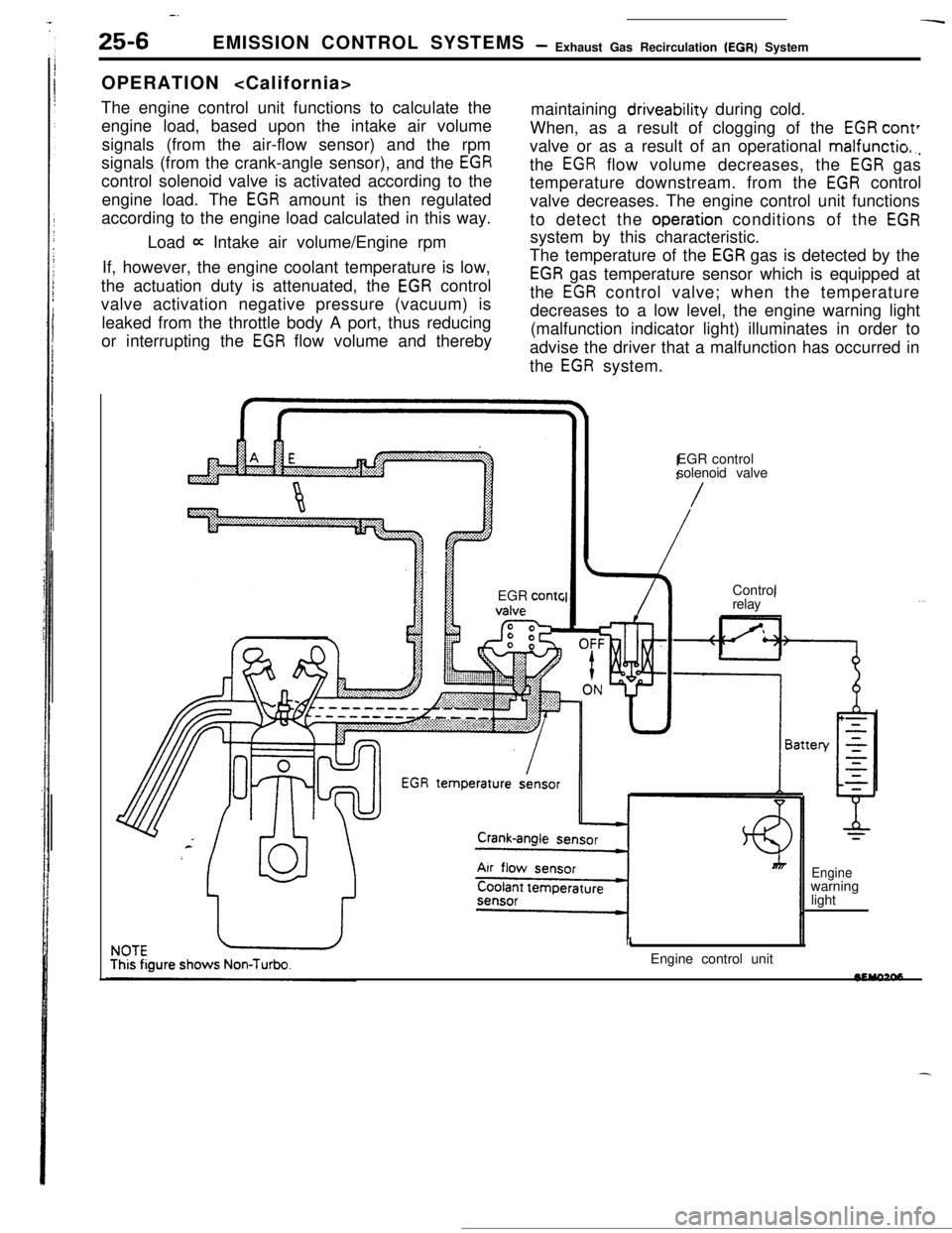
The engine control unit functions to calculate the
engine load, based upon the intake air volume
signals (from the air-flow sensor) and the rpm
signals (from the crank-angle sensor), and the
EGRcontrol solenoid valve is activated according to the
engine load. The
EGR amount is then regulated
according to the engine load calculated in this way.maintaining driveability during cold.
When, as a result of clogging of the
EGR cant’valve or as a result of an operational
malfunctio,.,the
EGR flow volume decreases, the EGR gas
temperature downstream. from the
EGR control
valve decreases. The engine control unit functions
to detect the
operation conditions of the EGRLoad
a Intake air volume/Engine rpmsystem by this characteristic.
If, however, the engine coolant temperature is low,
the actuation duty is attenuated, the
EGR control
valve activation negative pressure (vacuum) is
leaked from the throttle body A port, thus reducing
or interrupting the
EGR flow volume and therebyThe temperature of the
EGR gas is detected by the
EGR gas temperature sensor which is equipped at
the
EGR control valve; when the temperature
decreases to a low level, the engine warning light
(malfunction indicator light) illuminates in order to
advise the driver that a malfunction has occurred in
the
EGR system.
EGR
contcEGR control
solenoid valve
/Control
relay
1Engine control unit
Enginewarning
light