MITSUBISHI ECLIPSE 1990 Service Manual
Manufacturer: MITSUBISHI, Model Year: 1990, Model line: ECLIPSE, Model: MITSUBISHI ECLIPSE 1990Pages: 391, PDF Size: 15.27 MB
Page 381 of 391
EMISSION CONTROL SYSTEMS - Exhaust Car Recirculation (EGR) System25-7Duty ratio
I .,
ON e-_-m-L--l
T2L1.TlOFF---
m
1c1-i1e2100260 msec. 60 msec.
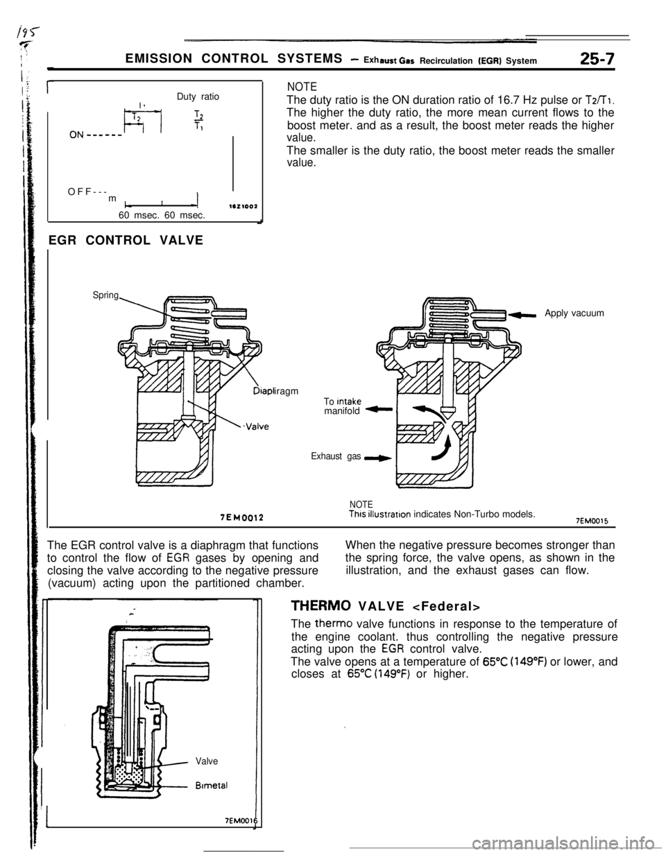
EGR CONTROL VALVE
Spring
NOTEThe duty ratio is the ON duration ratio of 16.7 Hz pulse or
T2/T1.The higher the duty ratio, the more mean current flows to the
boost meter. and as a result, the boost meter reads the higher
value.The smaller is the duty ratio, the boost meter reads the smaller
value.
Diapl
.Valveiragm
To Intakemanifold
Exhaust gasApply vacuum
7EM0012
NOTEThis illustration indicates Non-Turbo models.7EMOO15The EGR control valve is a diaphragm that functions
to control the flow of
EGR gases by opening and
closing the valve according to the negative pressure
(vacuum) acting upon the partitioned chamber.When the negative pressure becomes stronger than
the spring force, the valve opens, as shown in the
illustration, and the exhaust gases can flow.
Valve
BlmetzII
17EMOO16
THERM0 VALVE
The therm0 valve functions in response to the temperature of
the engine coolant. thus controlling the negative pressure
acting upon the
EGR control valve.
The valve opens at a temperature of
65°C (149°F) or lower, and
closes at
65°C (149°F) or higher.
Page 382 of 391
25-8EMISSION CONTROL SYSTEMS- Exhaust Gas Recirculation (EGR) System
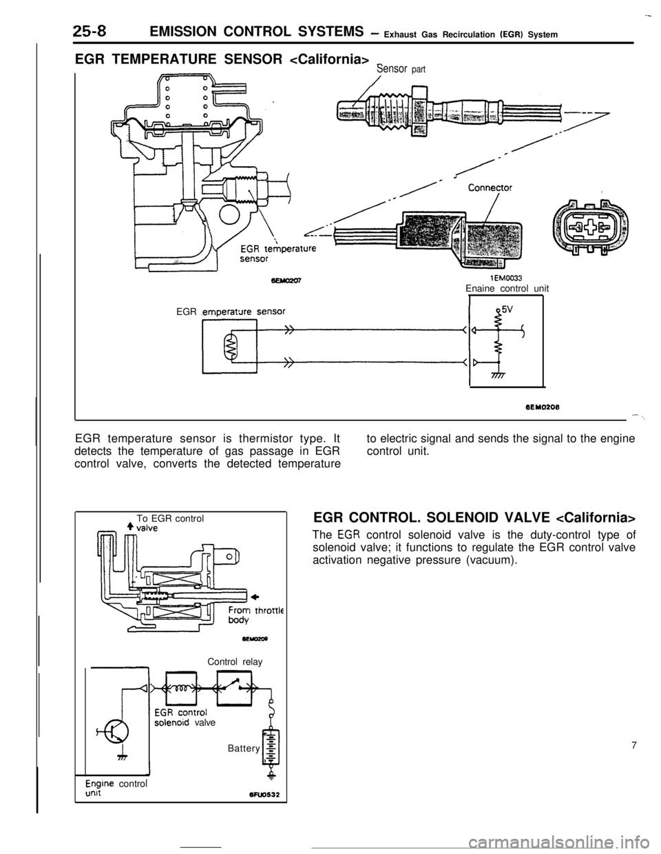
EGR TEMPERATURE SENSOR
_Sensor part
/
/-
/* * Conneyor,
lEM0033Enaine control unit
EGR temperature sensor
Kf+
--
6EY0208--\EGR temperature sensor is thermistor type. It
detects the temperature of gas passage in EGR
control valve, converts the detected temperatureto electric signal and sends the signal to the engine
control unit.
To EGR control
+I thl
.ottleControl relay
solenoid valve
h
LBattery
g
0s
l$ine control5FW532EGR CONTROL. SOLENOID VALVE
The
EGR control solenoid valve is the duty-control type of
solenoid valve; it functions to regulate the EGR control valve
activation negative pressure (vacuum).
7
Page 383 of 391
---- .~ _ _EMISSION CONTROL SYSTEMS
- Catalytic Converter I Air-fuel Mixture Ratio Control System25-9
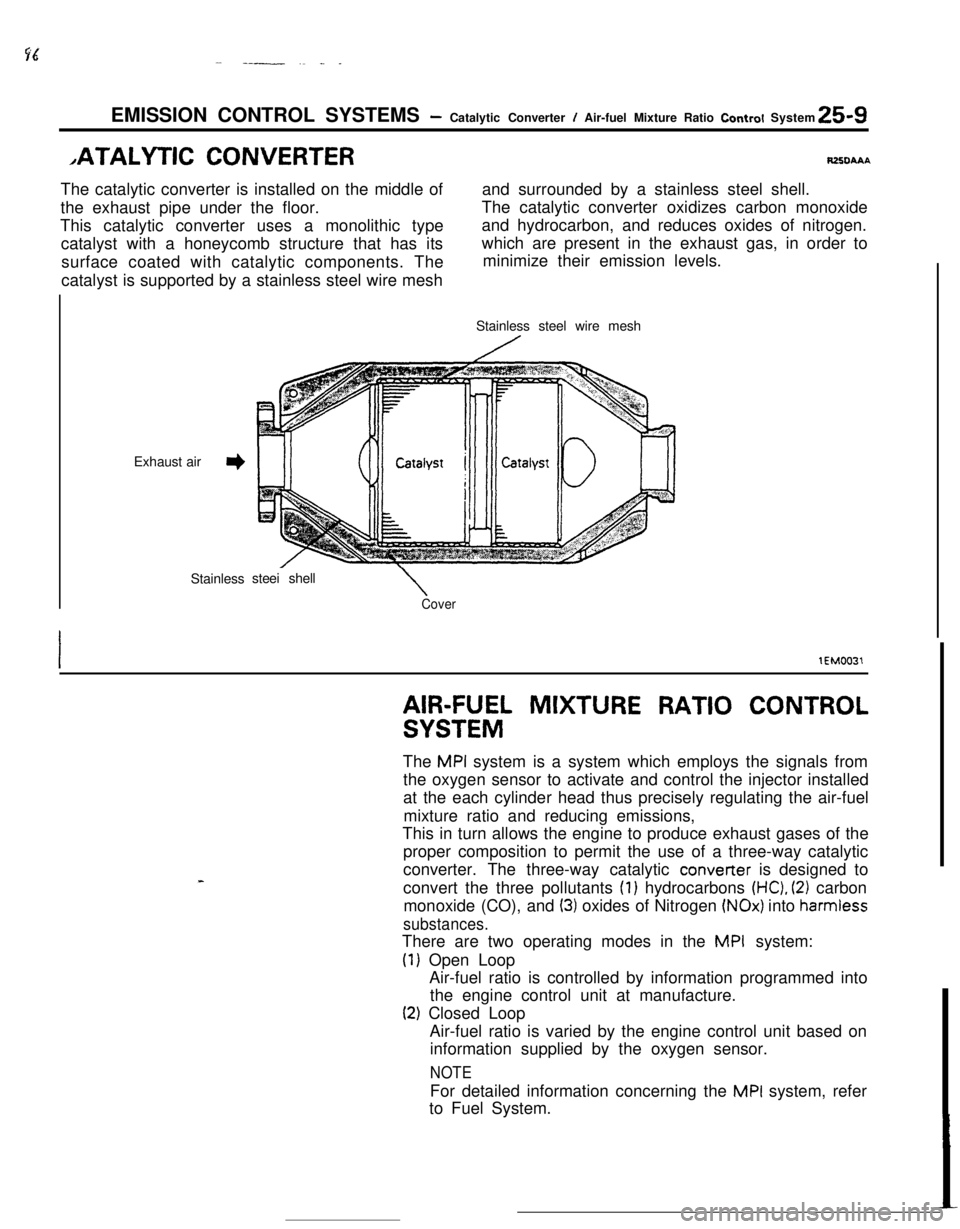
,ATALYTlC CONVERTERRZXIAAAThe catalytic converter is installed on the middle ofand surrounded by a stainless steel shell.
the exhaust pipe under the floor.The catalytic converter oxidizes carbon monoxide
This catalytic converter uses a monolithic type
catalyst with a honeycomb structure that has itsand hydrocarbon, and reduces oxides of nitrogen.
surface coated with catalytic components. Thewhich are present in the exhaust gas, in order to
minimize their emission levels.
catalyst is supported by a stainless steel wire mesh
Exhaust air
3Stainlesssteei shell
\CoverStainless steel wire mesh
lEM0031
AIR-FUEL MIXTURE RATIO CONTROL
SYSTEMThe
MPI system is a system which employs the signals from
the oxygen sensor to activate and control the injector installed
at the each cylinder head thus precisely regulating the air-fuel
mixture ratio and reducing emissions,
This in turn allows the engine to produce exhaust gases of the
proper composition to permit the use of a three-way catalytic
converter. The three-way catalytic converter is designed to
convert the three pollutants
(1) hydrocarbons (HC), (2) carbon
monoxide (CO), and
(3) oxides of Nitrogen (NOx) into harmiess
substances.There are two operating modes in the
MPI system:
(1) Open Loop
Air-fuel ratio is controlled by information programmed into
the engine control unit at manufacture.
(2) Closed Loop
Air-fuel ratio is varied by the engine control unit based on
information supplied by the oxygen sensor.
NOTEFor detailed information concerning the
MPI system, refer
to Fuel System.
Page 384 of 391
25-10EMISSION CONTROL SYSTEMS - Crankcase Ventilation Svstem-
CRANKCASE VENTILATION SYS-fUSFAAA,r
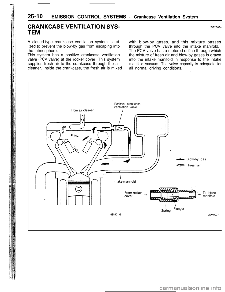
TEMA closed-type crankcase ventilation system is
uti-with blow-by gases, and this mixture passes
lized to prevent the blow-by gas from escaping into
through the PCV valve into the intake manifold.
the atmosphere.The PCV valve has a metered orifice through which
This system has a positive crankcase ventilation
the mixture of fresh air and blow-by gases is drawn
valve
(PCV valve) at the rocker cover. This system
into the intake manifold in response to the intake
supplies fresh air to the crankcase through the air
manifold vacuum. The valve capacity is adequate forcleaner. Inside the crankcase, the fresh air is mixed
all normal driving conditions.
From air cleanerPositive crankcaseventilation valve
a Blow-by gas
a Freshair
To intakemanifold
6EM0115
SiringPlunger
7EMOOZi
Page 385 of 391
__..--. -._ _^__. __--- -._ _..EMISSION CONTROL SYSTEMS
- Evaporative Emission Control Svsvem25-l 1
,VAPORATlVE EMISSION CON-
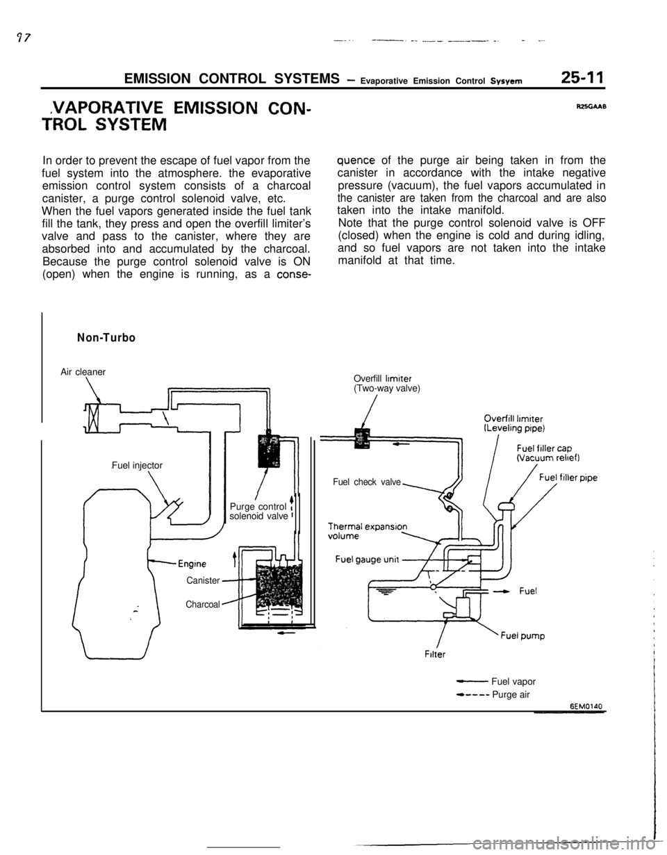
TROL SYSTEMIn order to prevent the escape of fuel vapor from the
fuel system into the atmosphere. the evaporative
emission control system consists of a charcoal
canister, a purge control solenoid valve, etc.
When the fuel vapors generated inside the fuel tank
fill the tank, they press and open the overfill limiter’s
valve and pass to the canister, where they are
absorbed into and accumulated by the charcoal.
Because the purge control solenoid valve is ON
(open) when the engine is running, as a
conse-
Non-TurboAir cleaner
Fuel injector
Canister
Charcoal
/Purge control tsolenoid valve r
RZSGAAB
quence of the purge air being taken in from the
canister in accordance with the intake negative
pressure (vacuum), the fuel vapors accumulated in
the canister are taken from the charcoal and are alsotaken into the intake manifold.
Note that the purge control solenoid valve is OFF
(closed) when the engine is cold and during idling,
and so fuel vapors are not taken into the intake
manifold at that time.
Overfill
limiter(Two-way valve)
Fuel check valveFilter
- Fuel vapor
*---- Purge air
Page 386 of 391
25-12EMISSION CONTROL SYSTEMS- Evaporative Emisson Control System-
TurboPurge control valve
/Air cleaner
Canister
-Charcoal-ITurbo-
chargerPurge control
solenoid valve
Fuel check valve
Thermal expansion
Fuel gauge unit
Filter
- Fuel vapor
- - - - Purge air
BEMO211
%-E?”solenoidvalve
Charcoal -fuel tank
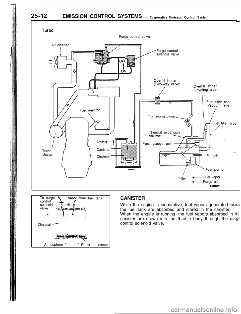
CANISTERWhile the engine is inoperative, fuel vapors generated
insidEthe fuel tank are absorbed and stored in the canister.
When the engine is running, the fuel vapors absorbed in
thfcanister are drawn into the throttle body through the
purgecontrol solenoid valve.
Atmosphere
L- Filter03Roo3E
Page 387 of 391

EMISSION CONTROL SYSTEMS- Evaporative Emission Control System25-13
IFrom canister1
,To intake air plenum or throttle body
7EMOlPControl
relavPurge control
solenoid valve
Battery
g
6
,zEngine control
unit
From throttle body
4To purge
control
valve
SEMo2laControl relay
3:
1.
Purge control
solenoid valve
zBattery g
Engtne controlunii
bfuo532JPURGE CONTROL SOLENOID VALVE
The purge-control solenoid valve is the ON/OFF control type of
solenoid valve; it functions to control the introduction of purge
air to the intake air plenum from the canister.
PURGE CONTROL SOLENOID VALVE
The purge-control solenoid valve is the ON/OFF control type of
solenoid valve; it functions to control the activation of the
purge-control valve.
ITo throttle body11PURGE CONTROL VALVE
The purge-control valve functions to control the introduction of
purge air to the air-intake hose from the canister.
0 From canister
Page 388 of 391
--.25-14EMISSION CONTROL SYSTEMS
- Evaporative Emisson Control System
Pressure valveTo overfill
’ limiter
40
” Ball
Bail
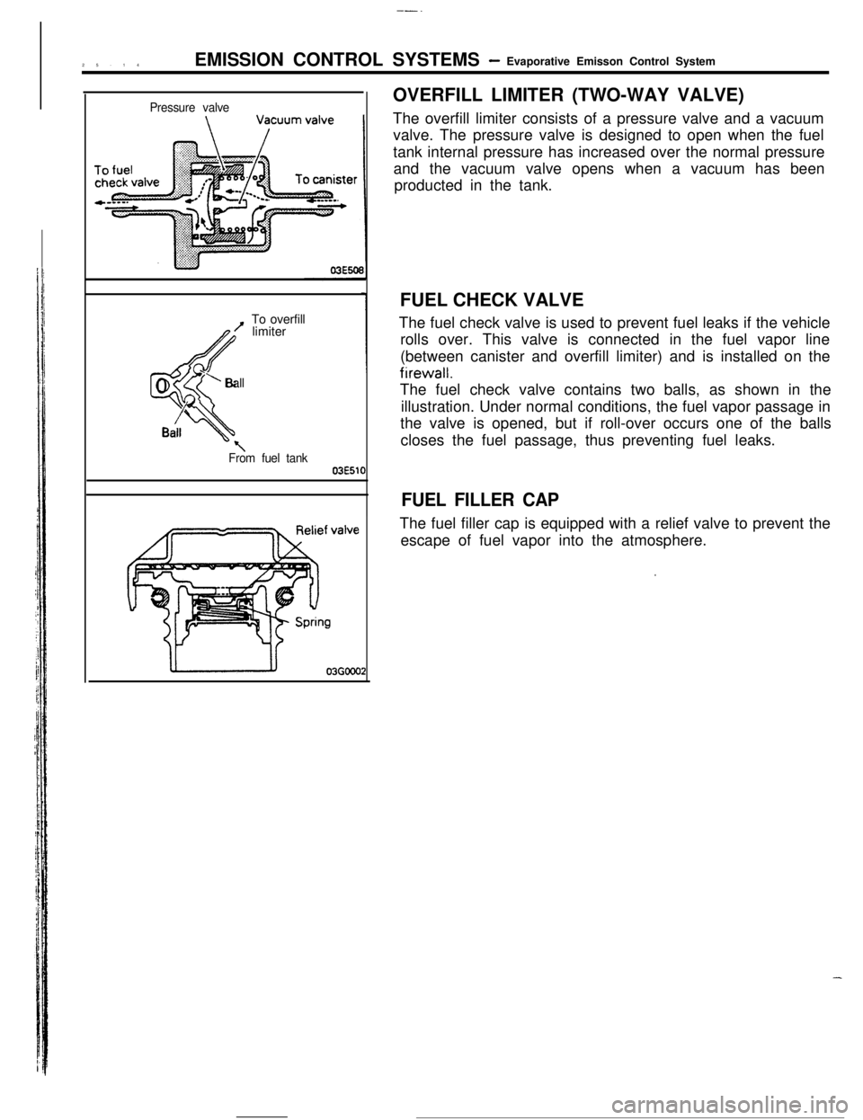
\From fuel tank03E51fOVERFILL LIMITER (TWO-WAY VALVE)
The overfill limiter consists of a pressure valve and a vacuum
valve. The pressure valve is designed to open when the fuel
tank internal pressure has increased over the normal pressure
and the vacuum valve opens when a vacuum has been
producted in the tank.
FUEL CHECK VALVE
The fuel check valve is used to prevent fuel leaks if the vehicle
rolls over. This valve is connected in the fuel vapor line
(between canister and overfill limiter) and is installed on thefirewall.
The fuel check valve contains two balls, as shown in the
illustration. Under normal conditions, the fuel vapor passage in
the valve is opened, but if roll-over occurs one of the balls
closes the fuel passage, thus preventing fuel leaks.
FUEL FILLER CAPThe fuel filler cap is equipped with a relief valve to prevent the
escape of fuel vapor into the atmosphere.
.
-
Page 389 of 391

-_--
NOTES
Page 390 of 391

-_--
NOTES