MITSUBISHI ECLIPSE 1990 Repair Manual
ECLIPSE 1990
MITSUBISHI
MITSUBISHI
https://www.carmanualsonline.info/img/19/57103/w960_57103-0.png
MITSUBISHI ECLIPSE 1990 Repair Manual
Trending: fog light, brake light, heating, lights, ignition, heater, oil type
Page 61 of 391
33.- .1S~IUlj~%L...i-.ELECTRICAL
- Relays, Control Units and Sensors
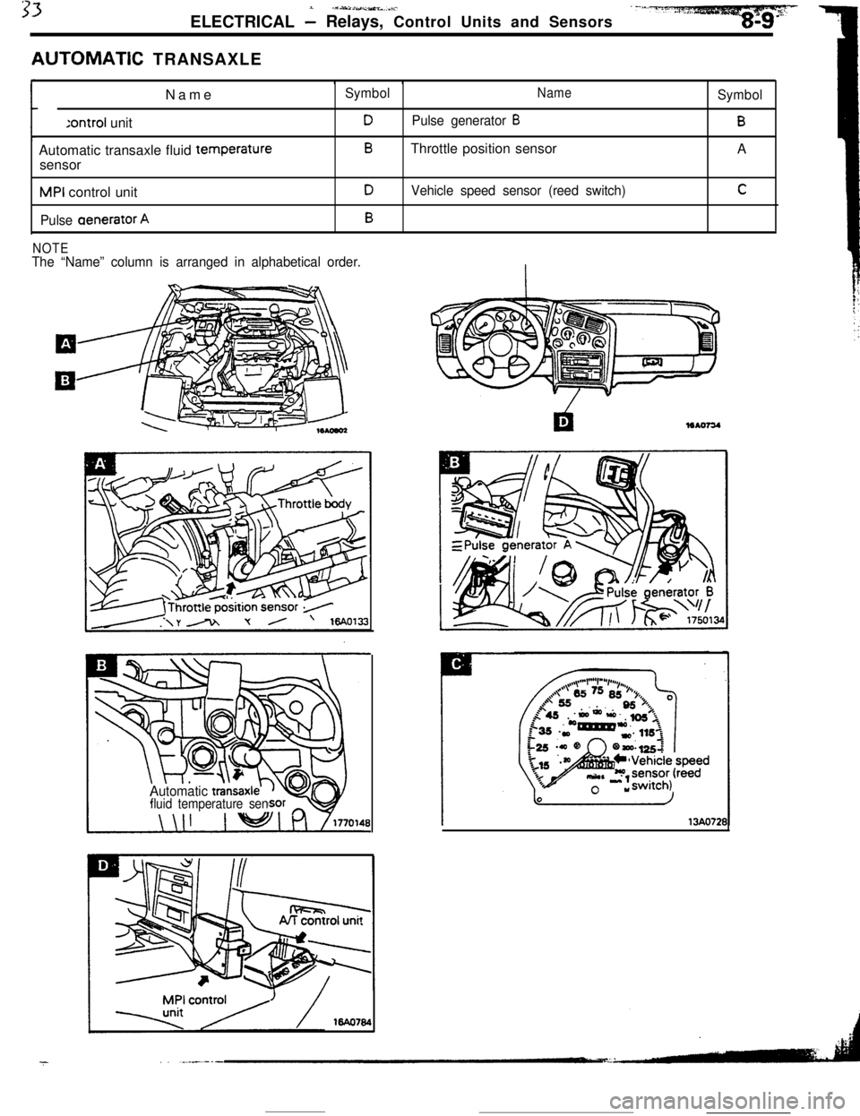
AUTOMATiC TRANSAXLE
Name:ontroi unit
Automatic transaxle fluid temperature
sensorMPI control unit
Pulse aenerator A
SymbolNameSymbol
DPulse generator BB
BThrottle position sensor
A
DVehicle speed sensor (reed switch)C
B
NOTEThe “Name” column is arranged in alphabetical order.
Automatic
transaxlfluid temperature sen
16440784
13AO721
Page 62 of 391
_--__ .-
I8-10ELECTRICAL -Relays, Control Units and Sensors
I
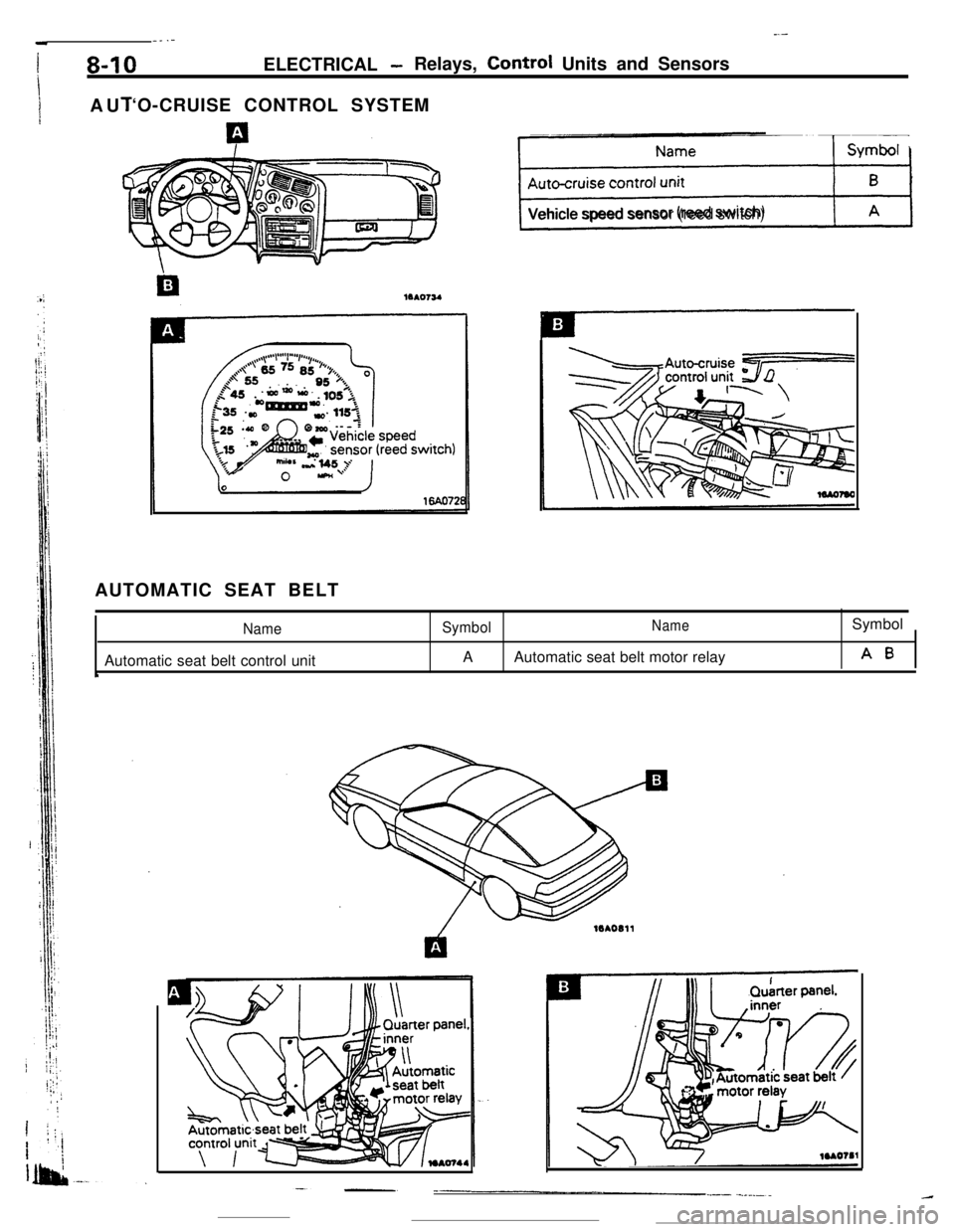
1AUI‘O-CRUISE CONTROL SYSTEM
ps+%JVehicle speed sensor (reed switch)
AUTOMATIC SEAT BELT
NameAutomatic seat belt control unit
‘
SymbolNameSymbol
AAutomatic seat belt motor relay
A0
Page 63 of 391
1ELECTRICAL
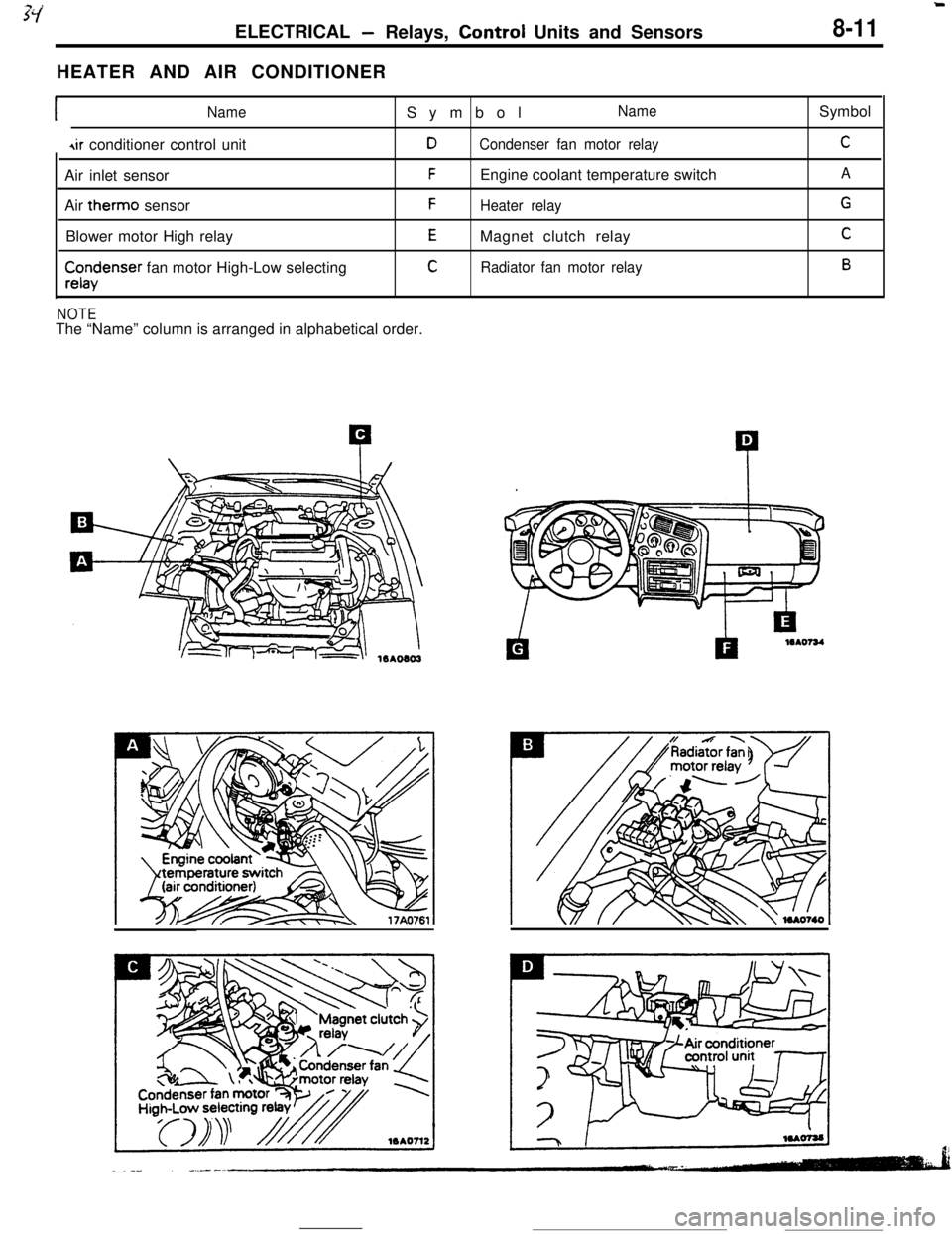
-Relays, Control Units and Sensors8-11HEATER AND AIR CONDITIONER
INameSymbolName
4ir conditioner control unitDCondenser fan motor relayAir inlet sensor
FEngine coolant temperature switch
Air therm0 sensor
FHeater relayBlower motor High relay
EMagnet clutch relay
$x$enser fan motor High-Low selectingCRadiator fan motor relay
NOTEThe “Name” column is arranged in alphabetical order.Symbol
C
A
G
C
B
Page 64 of 391
__ .__-.... . - -----8-12ELECTRICAL
-Relays, Control Units and Sensors
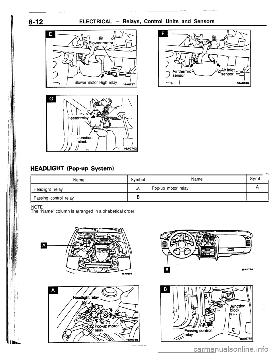
Blower motor High relay,,,A,
HEADLIGHT (Pop-up System)-7
NameSymbolNameSymt
Headlight relay.APop-up motor relayA
Passing control relayB
NOTEThe “Name” column is arranged in alphabetical order.
+Junction \-- 1block\-
Page 65 of 391
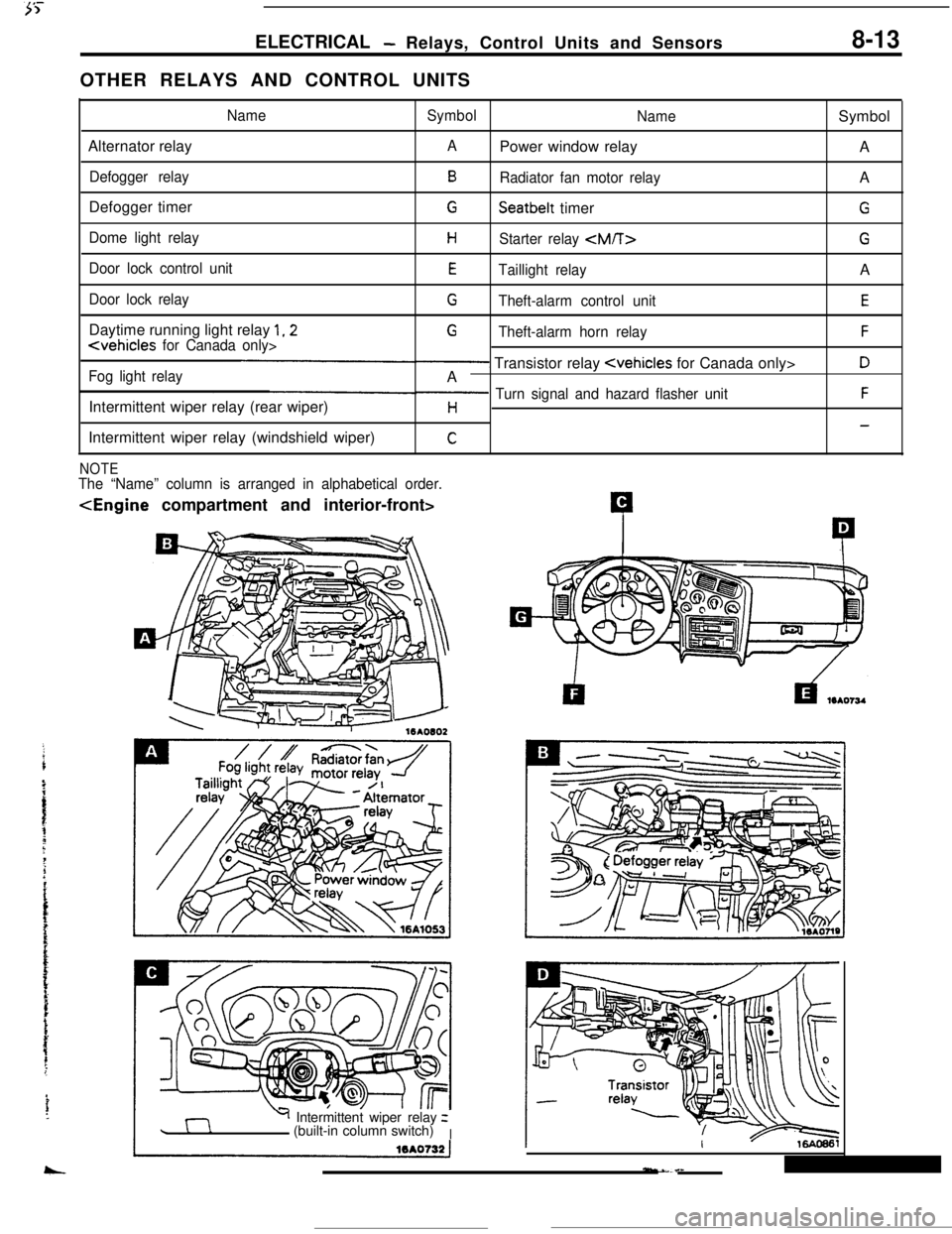
ELECTRICAL- Relays, Control Units and Sensors8-13OTHER RELAYS AND CONTROL UNITS
NameSymbol
NameSymbol
Alternator relay
APower window relay
A
Defogger relayBRadiator fan motor relayA
Defogger timer
GSeatbelt timerG
Dome light relayHStarter relay G
Door lock control unitETaillight relayA
Door lock relayGTheft-alarm control unitEDaytime running light relay
1,2GTheft-alarm horn relayF
Fog light relay- Transistor relay DA
Intermittent wiper relay (rear wiper)
p Turn signal and hazard flasher unitFH-Intermittent wiper relay (windshield wiper)
C
NOTEThe “Name” column is arranged in alphabetical order.
Y Intermittent wiper relayz
(built-in column switch)
I
Page 66 of 391
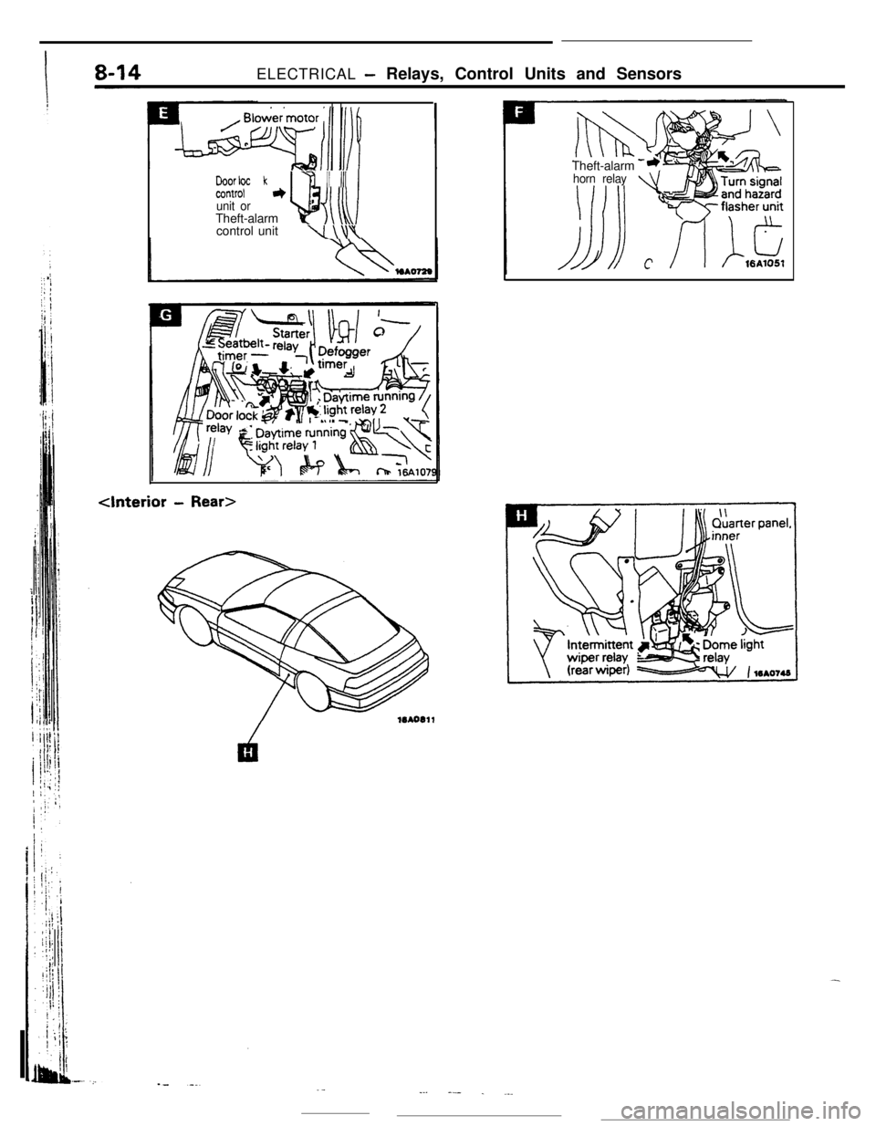
ELECTRICAL - Relays, Control Units and Sensors
b%YrF k7 II III~
unit orTheft-alarmucontrol unit
\I\\\
- Rear>Theft-alarm
horn relay
._--. --- . ._.
Page 67 of 391
. . .&L : __,ELECTRICAL
- Inspection Terminal
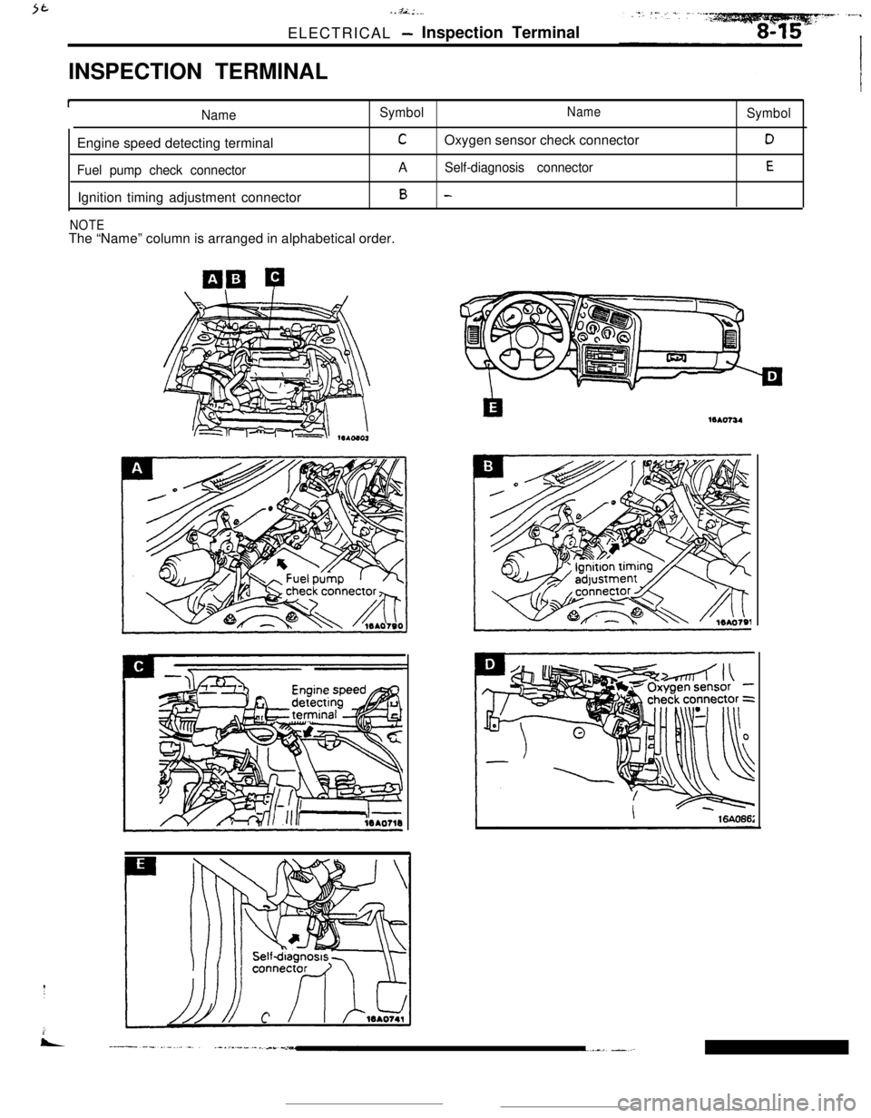
INSPECTION TERMINAL
INameSymbolNameEngine speed detecting terminal
COxygen sensor check connector
Fuel pump check connectorASelf-diagnosis connectorIgnition timing adjustment connector
B -
NOTEThe “Name” column is arranged in alphabetical order.
Symbol
D
E16Ao734
Page 68 of 391
8-16ELECTRICAL - Lighting
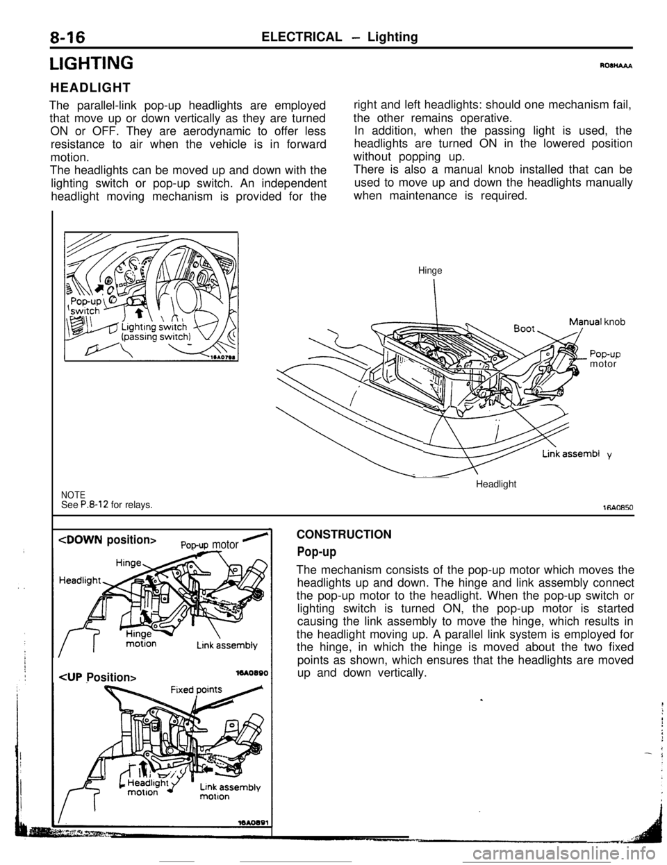
LIGHTINGHEADLIGHT
The parallel-link pop-up headlights are employed
that move up or down vertically as they are turned
ON or OFF. They are aerodynamic to offer less
resistance to air when the vehicle is in forward
motion.
The headlights can be moved up and down with the
lighting switch or pop-up switch. An independent
headlight moving mechanism is provided for theRo3liAAAright and left headlights: should one mechanism fail,
the other remains operative.
In addition, when the passing light is used, the
headlights are turned ON in the lowered position
without popping up.
There is also a manual knob installed that can be
used to move up and down the headlights manually
when maintenance is required.
nual knob
POD-UD
NOTESee P.8-12 for relays.
Hinge
-r -rmotor
~ SpsernbI y_Headlight
1RAoa50
Pop-up motor ’
16AOWOCONSTRUCTION
Pop-upThe mechanism consists of the pop-up motor which moves the
headlights up and down. The hinge and link assembly connect
the pop-up motor to the headlight. When the pop-up switch or
lighting switch is turned ON, the pop-up motor is started
causing the link assembly to move the hinge, which results in
the headlight moving up. A parallel link system is employed for
the hinge, in which the hinge is moved about the two fixed
points as shown, which ensures that the headlights are moved
up and down vertically.
.
Page 69 of 391
ELECTRICAL - Lighting8-17
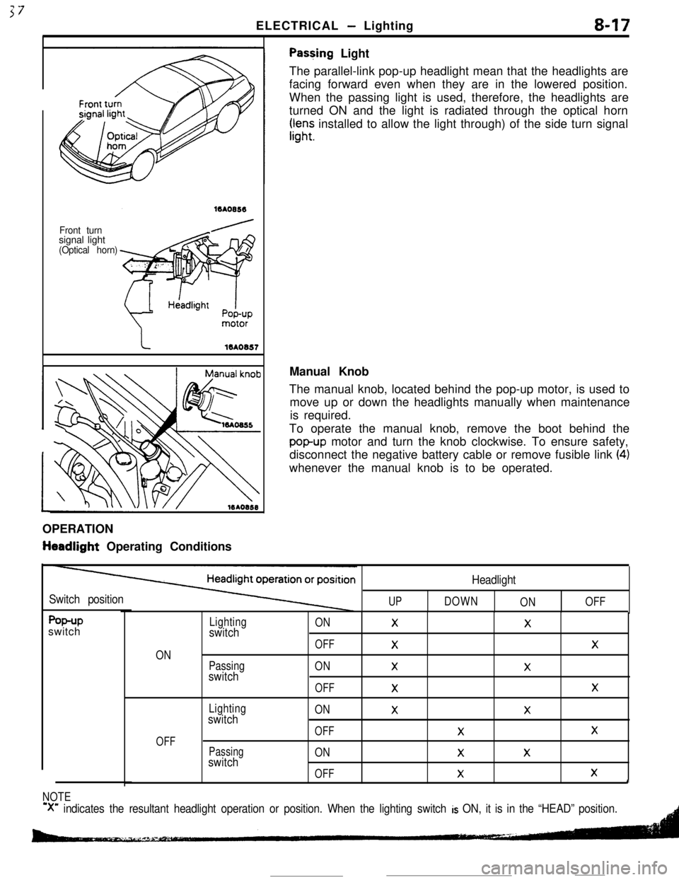
Front turnsignal light
(Optical horn)
Pas+ing Light
The parallel-link pop-up headlight mean that the headlights are
facing forward even when they are in the lowered position.
When the passing light is used, therefore, the headlights are
turned ON and the light is radiated through the optical horn
rr,“;; installed to allow the light through) of the side turn signal
OPERATION
tieadlight Operating ConditionsManual Knob
The manual knob, located behind the pop-up motor, is used to
move up or down the headlights manually when maintenance
is required.
To operate the manual knob, remove the boot behind the
popup motor and turn the knob clockwise. To ensure safety,
disconnect the negative battery cable or remove fusible link
(4)whenever the manual knob is to be operated.
Switch positionUP
Headlight
DOWN
ONOFF
f%+Pswitch
ON
OFF
Lightingswitch
Passingswitch
Lightingswitch
Passingswitch
ONXX
OFF
XX
ONXX
OFF
XX
ONXX
OFFXX
ONXX
OFF
XXI
NOTE
‘X” indicates the resultant headlight operation or position. When the lighting switch is ON, it is in the “HEAD” position.
Page 70 of 391
8-18ELECTRICAL - Lighting
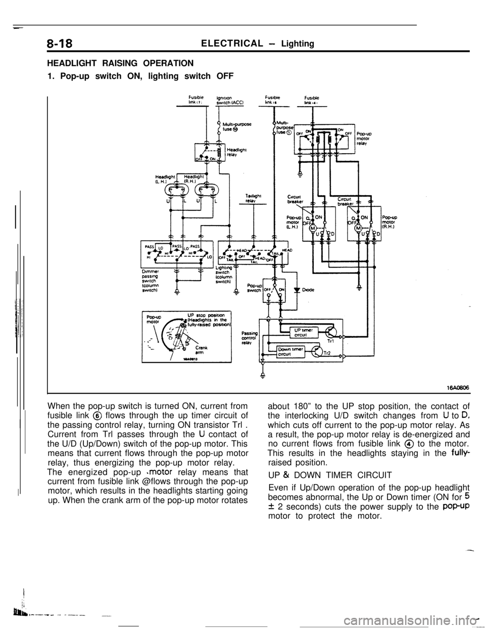
HEADLIGHT RAISING OPERATION
1. Pop-up switch ON, lighting switch OFF
When the pop-up switch is turned ON, current from
fusible link @ flows through the up timer circuit of
the passing control relay, turning ON transistor Trl .
Current from Trl passes through the
U contact of
the U/D (Up/Down) switch of the pop-up motor. This
means that current flows through the pop-up motor
relay, thus energizing the pop-up motor relay.
The energized pop-up
*motor relay means that
current from fusible link @flows through the pop-up
motor, which results in the headlights starting going
up. When the crank arm of the pop-up motor rotatesabout 180” to the UP stop position, the contact of
the interlocking U/D switch changes from
U to D,which cuts off current to the pop-up motor relay. As
a result, the pop-up motor relay is de-energized and
no current flows from fusible link @ to the motor.
This results in the headlights staying in the fully-
raised position.
UP
& DOWN TIMER CIRCUIT
Even if Up/Down operation of the pop-up headlight
becomes abnormal, the Up or Down timer (ON for
5
f 2 seconds) cuts the power supply to the POP-UPmotor to protect the motor.
I
jj
bib,-.-.+. -- ------.__
Trending: crank, fuse box diagram, fuel reserve, 4WD, tire size, manual transmission, ignition
