MITSUBISHI ECLIPSE 1990 Manual PDF
Manufacturer: MITSUBISHI, Model Year: 1990, Model line: ECLIPSE, Model: MITSUBISHI ECLIPSE 1990Pages: 391, PDF Size: 15.27 MB
Page 71 of 391
. ...>A . ..-rr7.e.~/._.. . . . . ,ELECTRICAL
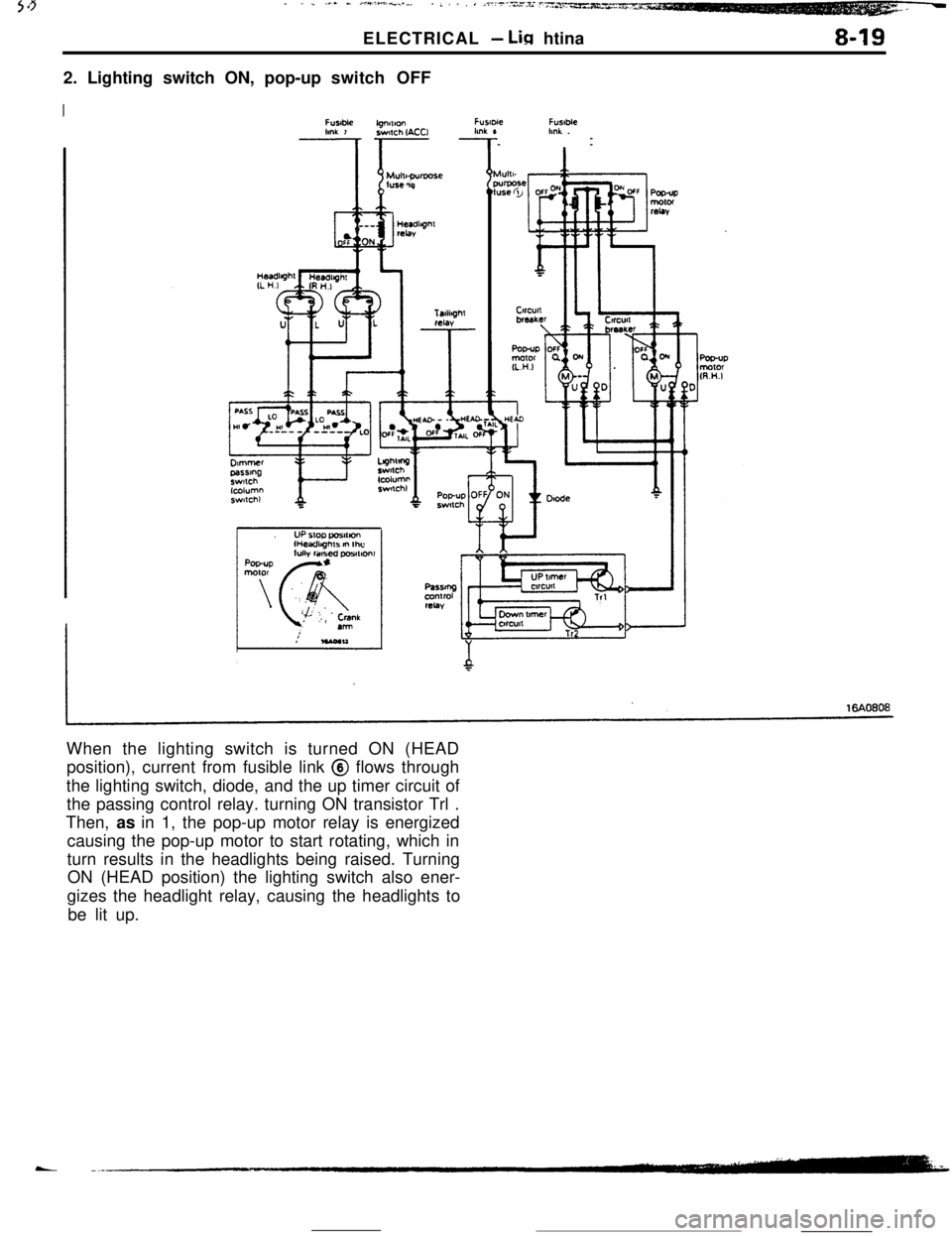
- Lin htina8-192. Lighting switch ON, pop-up switch OFF
IFtmbk
mr 7FlIU-ieFusableknk .
--
When the lighting switch is turned ON (HEAD
position), current from fusible link @ flows through
the lighting switch, diode, and the up timer circuit of
the passing control relay. turning ON transistor Trl .
Then, as in 1, the pop-up motor relay is energized
causing the pop-up motor to start rotating, which in
turn results in the headlights being raised. Turning
ON (HEAD position) the lighting switch also ener-
gizes the headlight relay, causing the headlights to
be lit up.
Page 72 of 391
_ -. _ -.__-ELECTRICAL
- Lighting
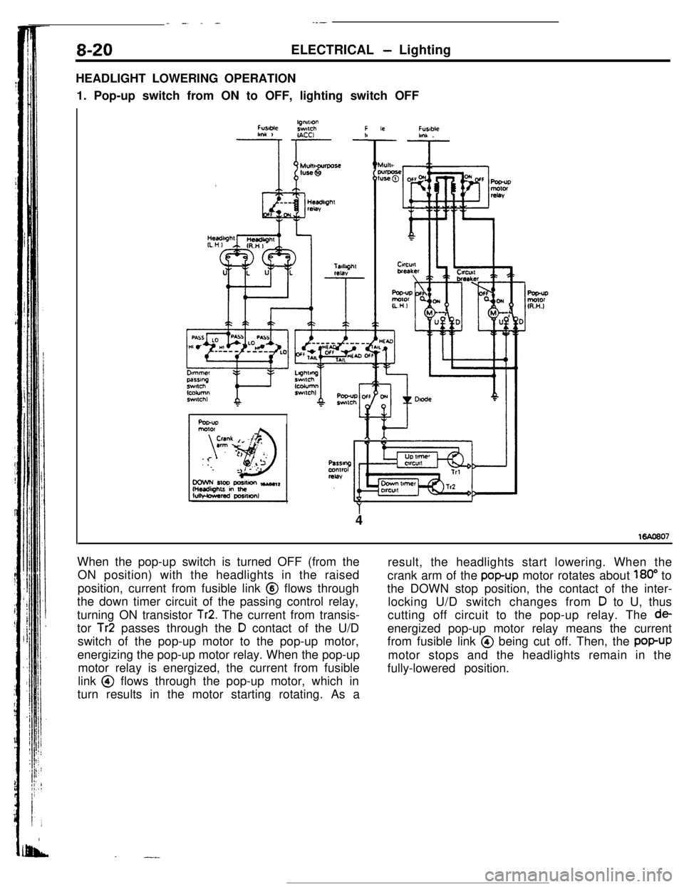
HEADLIGHT LOWERING OPERATION
1. Pop-up switch from ON to OFF, lighting switch OFF
FUslMelgnnlonswlchFlmk 1r- -!IACCI
Ar
Fusablehnk .
4
When the pop-up switch is turned OFF (from the
ON position) with the headlights in the raised
position, current from fusible link @ flows through
the down timer circuit of the passing control relay,
turning ON transistor
Tr2. The current from transis-
tor
Tr2 passes through the D contact of the U/D
switch of the pop-up motor to the pop-up motor,
energizing the pop-up motor relay. When the pop-up
motor relay is energized, the current from fusible
link @ flows through the pop-up motor, which in
turn results in the motor starting rotating. As a
.-.-result, the headlights start lowering. When the
crank arm of the
popup motor rotates about 180” to
the DOWN stop position, the contact of the inter-
locking U/D switch changes from
D to U, thus
cutting off circuit to the pop-up relay. The
deenergized pop-up motor relay means the current
from fusible link @ being cut off. Then, the
popUPmotor stops and the headlights remain in the
fully-lowered position.
Page 73 of 391
37..-. _.-.a*/ _ --‘-:.iA -i .- -..., mpv,,ELECTRICAL
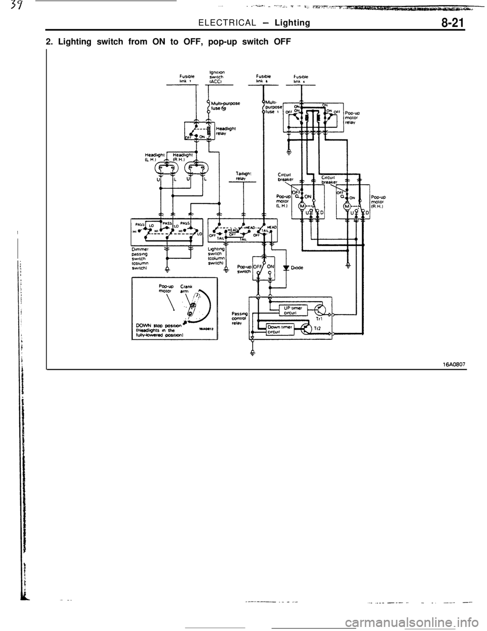
- Lighting8-212. Lighting switch from ON to OFF, pop-up switch OFF
-
16AO607
--.---- ._ - _-.._ ..-_ -_- -- _. --- --
Page 74 of 391
8-22ELECTRICAL - Lighting--Ignition ON
switch OFF
prDoor ON
switch OFF
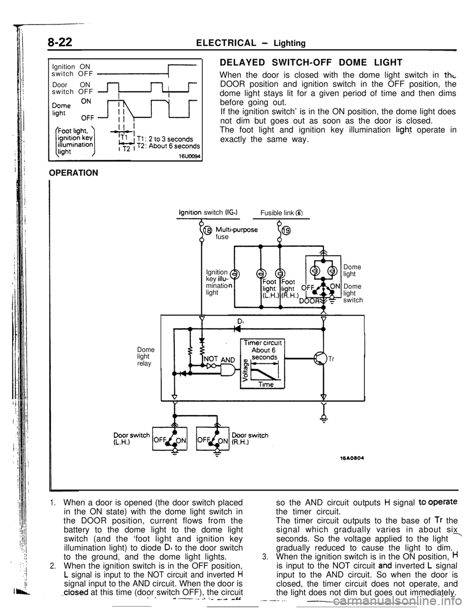
IDELAYED SWITCH-OFF DOME LIGHT
When the door is closed with the dome light switch in
thtDOOR position and ignition switch in the OFF position, the
dome light stays lit for a given period of time and then dims
before going out.
If the ignition switch’ is in the ON position, the dome light does
not dim but goes out as soon as the door is closed.
The foot light and ignition key illumination light operate in
exactly the same way.
16UOO94OPERATIONIgnition switch
(G)Fusible link a
Domelight
relay
9 Mutti-purpose
fuse
%69Ignition
key illu-
minatio
light
Domelight
Domelight
switch
Tr
;:16AO604
1.When a door is opened (the door switch placed
in the ON state) with the dome light switch in
the DOOR position, current flows from the
battery to the dome light to the dome light
switch (and the ‘foot light and ignition key
illumination light) to diode
DI to the door switch
to the ground, and the dome light lights.
2.When the ignition switch is in the OFF position,
L signal is input to the NOT circuit and inverted Hsignal input to the AND circuit. When the door is
-closed at this time (door switch OFF), the circuit
. .----es :- _.a -&Aso the AND circuit outputs
H signal to operate
the timer circuit.
The timer circuit outputs to the base of
Tr the
signal which gradually varies in about six
seconds. So the voltage applied to the light
-gradually reduced to cause the light to dim.
3.When the ignition switch is in the ON position,His input to the NOT circuit
ahd inverted L signal
input to the AND circuit. So when the door is
closed, the timer circuit does not operate, and
the light does not dim but goes out immediately.
_- .-._. ._-__._
Page 75 of 391
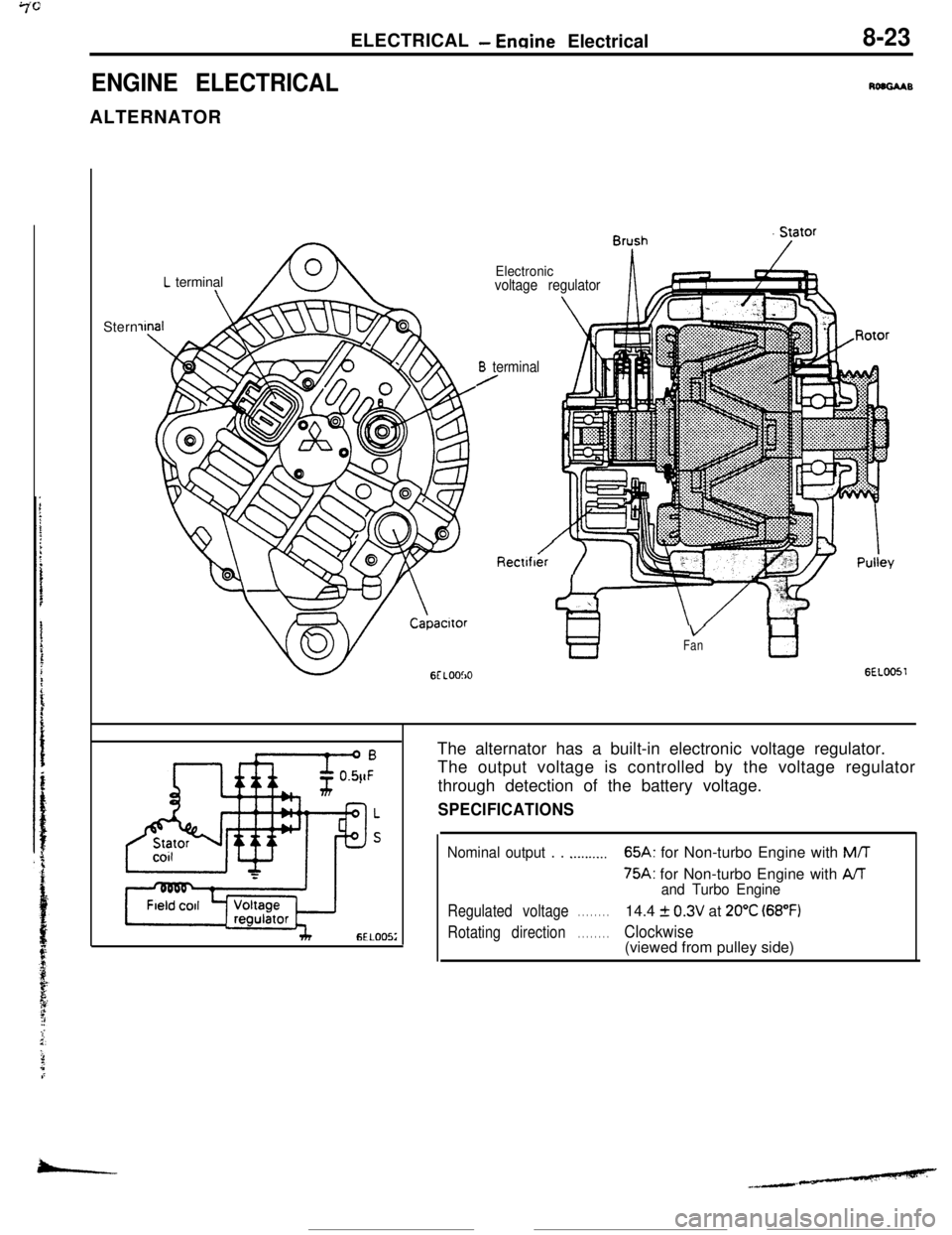
ELECTRICAL- Ermine Electrical8-23
ENGINE ELECTRICALRoaGAABALTERNATOR
L terminal\Stern
Electronicvoltage regulator
B terminal/
Rectlfber‘i ‘IT
VFantl
GEL0051The alternator has a built-in electronic voltage regulator.
The output voltage is controlled by the voltage regulator
through detection of the battery voltage.
SPECIFICATIONS
Nominal output . . .._...._..65A: for Non-turbo Engine with M/T
75A: for Non-turbo Engine with AAand Turbo Engine
Regulated voltage. . . . . . . .14.4 f 0.3V at 20°C (68°F)
Rotating direction. . . . . . . .Clockwise(viewed from pulley side)
-
Page 76 of 391
.-
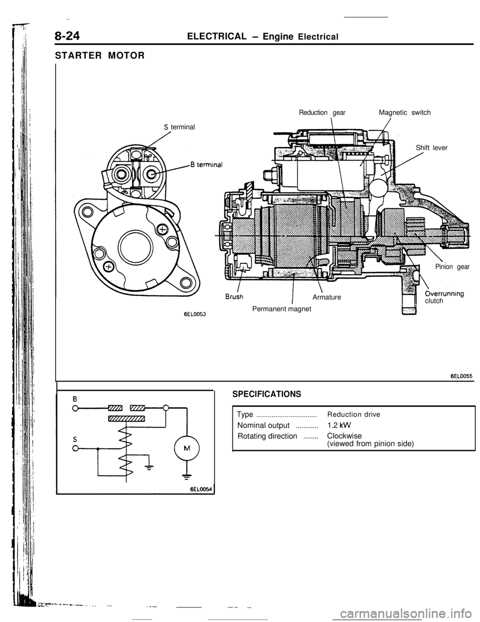
8-24ELECTRICAL- Engine Electrical
STARTER MOTOR
Reduction gearMagnetic switch
S terminal
Shift lever
6ELOO53
!n
IArmature
1Pinion gearOverrunnIng
hlclutch -Permanent magnet
6EL0055
SPECIFICATIONS
Type................................Reductiondrive
Nominal output
............1.2 kWRotating direction
........Clockwise
(viewed from pinion side)
-.- .-
Page 77 of 391
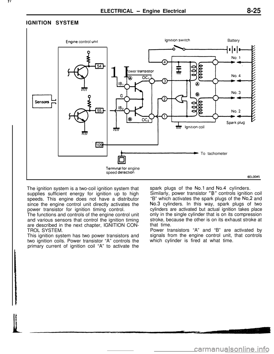
IGNITION SYSTEMELECTRICAL - Engine Electrical8-25
I
Sensors
Engine control unitlgnltlon switch
Battery
11 IPower transfstor
hhP 1
Ilgnltion coil
C To tachometerTerminal for engine
speed detectton
6ELOO45The ignition system is a two-coil ignition system that
supplies sufficient energy for ignition up to high
speeds. This engine does not have a distributor
since the engine control unit directly activates the
power transistor for ignition timing control.
The functions and controls of the engine control unit
and various sensors that control the ignition timing
are described in the next chapter, IGNITION CON-
TROL SYSTEM.
This ignition system has two power transistors and
two ignition coils. Power transistor “A” controls the
primary current of ignition coil “A” to activate thespark plugs of the
No.1 and No.4 cylinders.
Similarly, power transistor
“B” controls ignition coil
“B” which activates the spark plugs of the
No.2 and
No.3 cylinders. In this way, spark plugs of two
cylinders are activated but actual ignition takes placeonly in the single cylinder that is on its compression
stroke, because the other is on its exhaust stroke at
that time.
Power transistors “A” and “B” are activated by
signals from the engine control unit, that controls
which cylinder is fired at what time.
Page 78 of 391
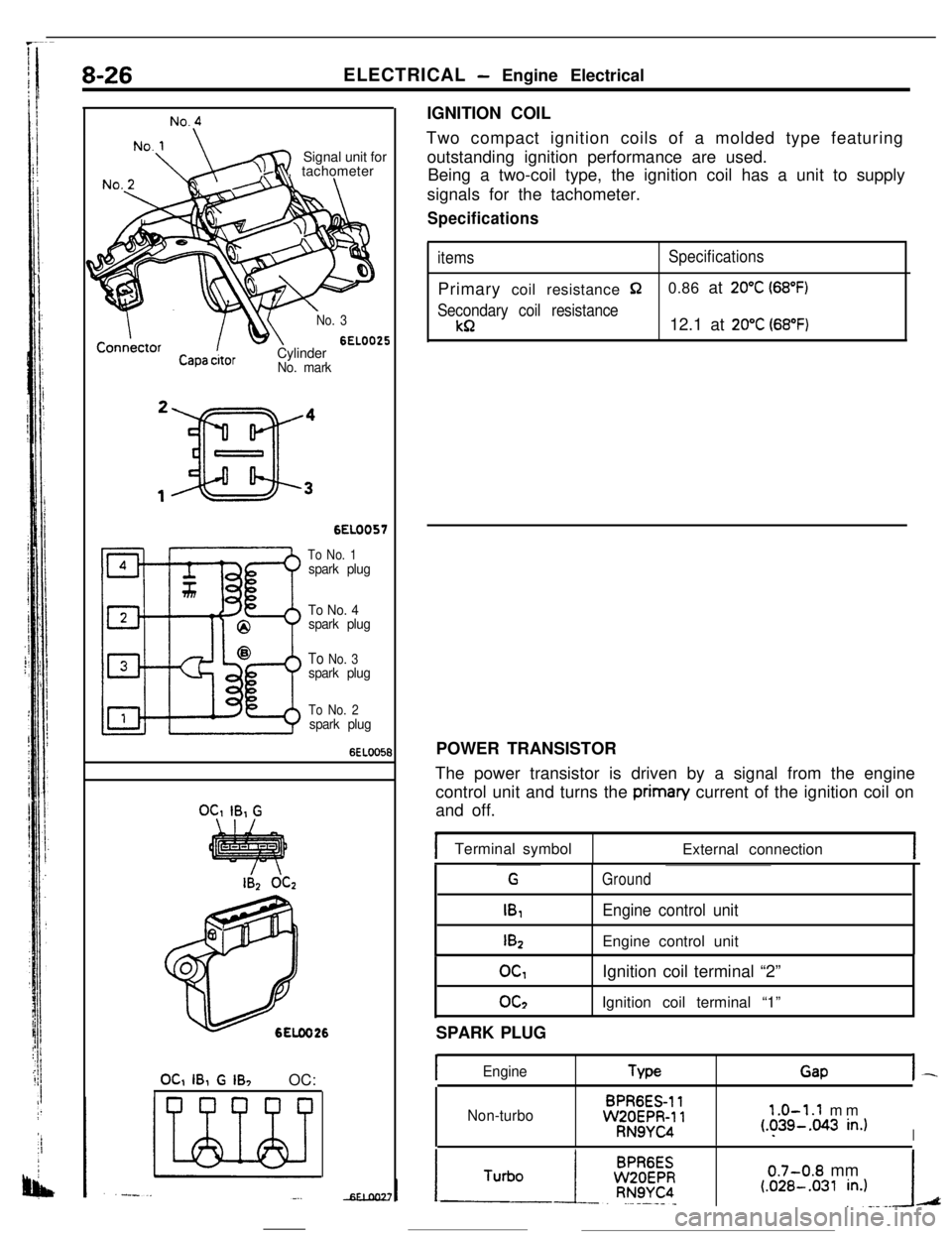
8-26ELECTRICAL - Engine Electrical
No.:
4Signal unit for
, tachometer
71
x
No. 3
6EL0025
Capa &orCylinderNo. mark
6EL0057
To No. 1spark plug
To No. 4
spark plug
To No. 3spark plug
To No. 2spark plug
6EL005t
OC,IB, G
OC, IB, G IB, OC:IGNITION COIL
Two compact ignition coils of a molded type featuring
outstanding ignition performance are used.
Being a two-coil type, the ignition coil has a unit to supply
signals for the tachometer.
Specifications
itemsSpecificationsPrimary coil resistance
$20.86 at 20°C (68°F)
Secondary coil resistance
kR12.1 at 20°C (68°F)POWER TRANSISTOR
The power transistor is driven by a signal from the engine
control unit and turns the priman/ current of the ignition coil on
and off.
Terminal symbol
External connection
G
IB,
I&
Ground
Engine control unitEngine control unit
OGoc2Ignition coil terminal “2”
Ignition coil terminal “1”
SPARK PLUG
IEngineTypeGapI-
Non-turboBPR6ES-11WZOEPR-11RN9YC4
1.0-1.1 mm(.?39-.043 in.)I
0.7-0.8 mm(.OZB-.031 in.)A
Page 79 of 391
-----. _-- ___ELECTRICAL
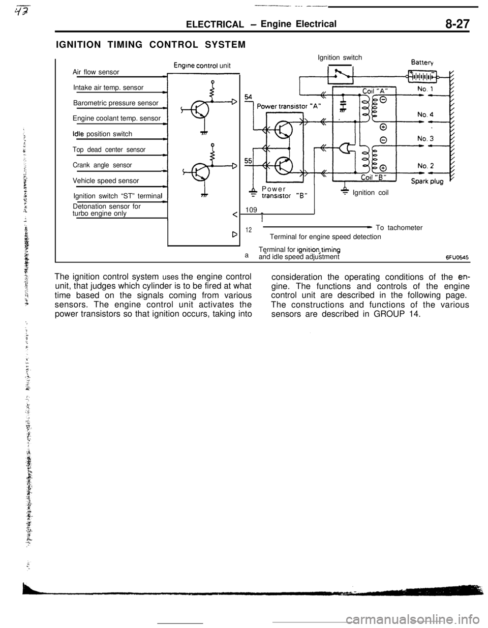
- Engine Electrical8-27IGNITION TIMING CONTROL SYSTEM
Air flow sensor
Engtne control unit
Intake air temp. sensor
Barometric pressure sensor
Engine coolant temp. sensorIdle position switch
:+
Top dead center sensor
Crank angle sensorVehicle speed sensor
;+Ignition switch “ST” terminal
Detonation sensor for
turbo engine only
4 Power= tranststor “B”P Ignition coil
109
_
I
1
12a”- To tachometer
Terminal for engine speed detection
Terminal for ignition,timing
and idle speed adjustment
6FUoE.45The ignition control system uses the engine control
consideration the operating conditions of the
en-unit, that judges which cylinder is to be fired at what
gine. The functions and controls of the engine
time based on the signals coming from variouscontrol unit are described in the following page.
sensors. The engine control unit activates the
The constructions and functions of the various
power transistors so that ignition occurs, taking into
sensors are described in GROUP 14.
Page 80 of 391
8-28ELECTRICAL- Engine Electrical
IGNITION TIMING CONTROL
Reading of Input signallgnitlon power
distribution control
(selection of power
transistor actlvatlon)Control mode
I II II IControl mode
dectsion data
Basic energlzatlon
I’
Engine control unitPower
Powertranststor “A”tranststor “B”
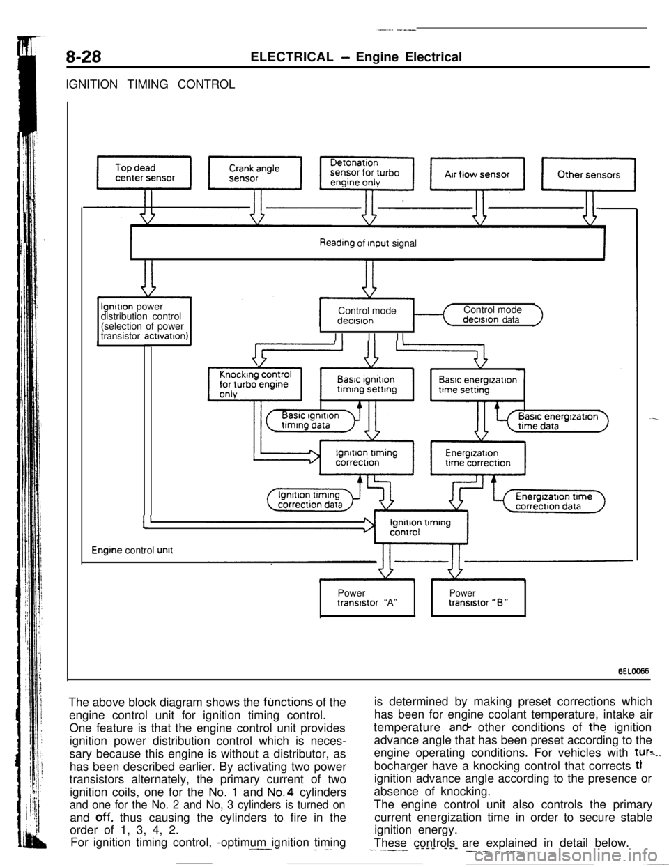
6ELOO66The above block diagram shows the
fljnctions of the
engine control unit for ignition timing control.
One feature is that the engine control unit provides
ignition power distribution control which is neces-
sary because this engine is without a distributor, as
has been described earlier. By activating two power
transistors alternately, the primary current of two
ignition coils, one for the No. 1 and No.4 cylinders
and one for the No. 2 and No, 3 cylinders is turned onand
off. thus causing the cylinders to fire in the
order of 1, 3, 4, 2.
For ignition timing control, -optimum ignition timing.^--_
_. -.is determined by making preset corrections which
has been for engine coolant temperature, intake air
temperature an& other conditions of the ignition
advance angle that has been preset according to the
engine operating conditions. For vehicles with
tur=_.bocharger have a knocking control that corrects tl
ignition advance angle according to the presence or
absence of knocking.
The engine control unit also controls the primary
current energization time in order to secure stable
ignition energy.
These controls are explained in detail below.
--. .----- ---- --- ___. .-. ___.,.__