MITSUBISHI ECLIPSE 1991 Service Manual
Manufacturer: MITSUBISHI, Model Year: 1991, Model line: ECLIPSE, Model: MITSUBISHI ECLIPSE 1991Pages: 1216, PDF Size: 67.42 MB
Page 1121 of 1216
BODY - Sunroof2397
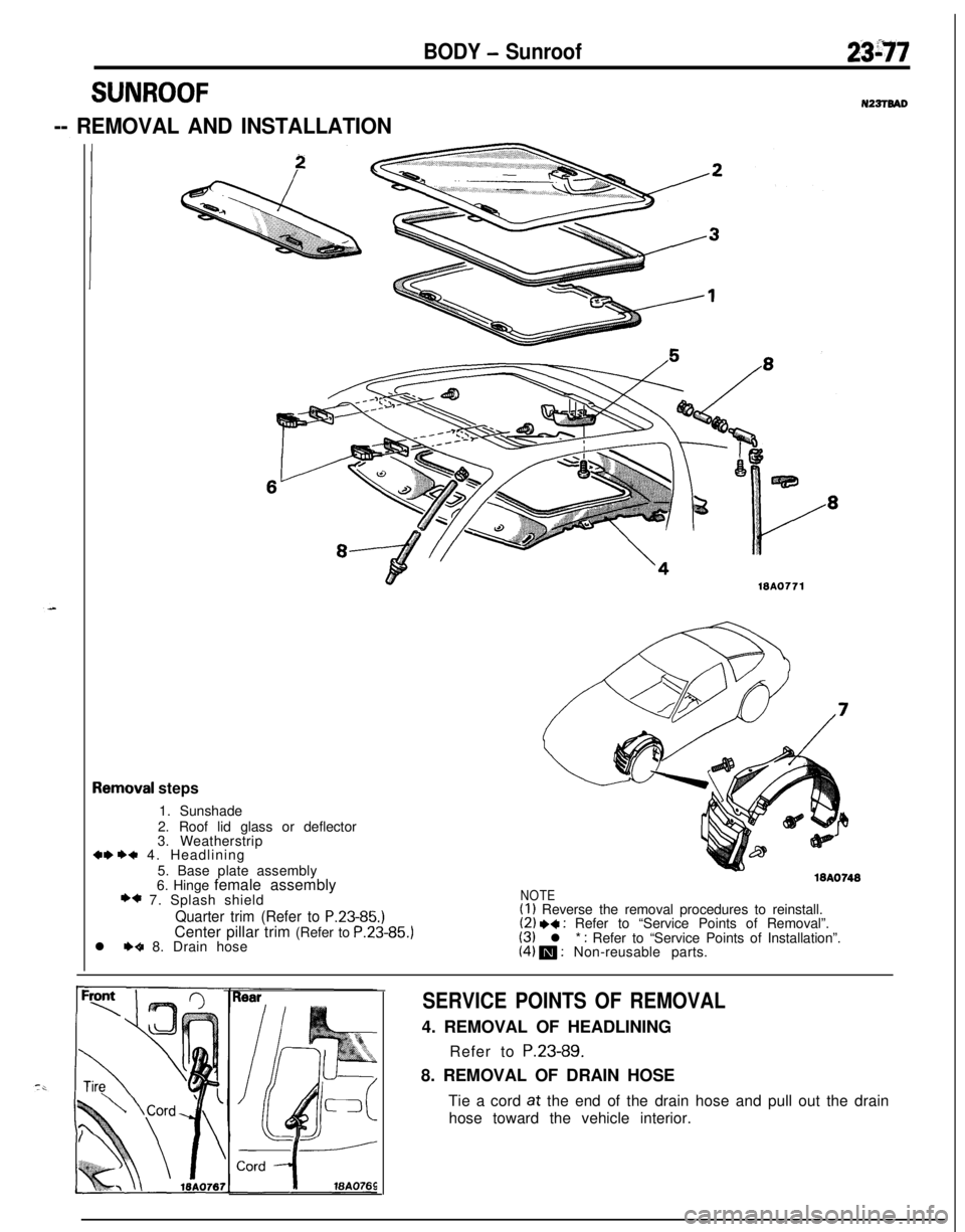
SUNROOFN22TTBAD
-- REMOVAL AND INSTALLATION
demoval steps
1. Sunshade
2. Roof lid glass or deflector
3. Weatherstrip
+w ++ 4. Headlining
5. Base plate assembly
6. Hinge female assembly
+* 7. Splash shield
Quarter trim (Refer to P.23-85.)Center pillar trim (Refer to P.23-85.)
l
++ 8. Drain hose
NOTE(I 1 Reverse the removal procedures to reinstall.(2) ** : Refer to “Service Points of Removal”.(3) l * : Refer to “Service Points of Installation”.(4) m : Non-reusable parts.
SERVICE POINTS OF REMOVAL4. REMOVAL OF HEADLINING
Refer to P.23-89.
8. REMOVAL OF DRAIN HOSE
Tie a cord
at the end of the drain hose and pull out the drain
hose toward the vehicle interior.
Page 1122 of 1216
23-78BODY - Sunroof
25-35
mm
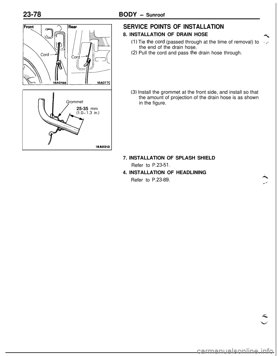
SERVICE POINTS OF INSTALLATION8. INSTALLATION OF DRAIN HOSE
AZ
(I) Tie the,cord (passed through at the time of removal) to. .ithe end of the drain hose.
(2) Pull the cord and pass t’he drain hose through.
(3) Install the grommet at the front side, and install so that
the amount of projection of the drain hose is as shown
in the figure.
7. INSTALLATION OF SPLASH SHIELD
Refer to
P.23-51.4. INSTALLATION OF HEADLINING
Refer to
P.23-89.
Page 1123 of 1216
23-78BODY -Instrument Panel23-79
INSTRUMENT PANELNZBUAAPI_-
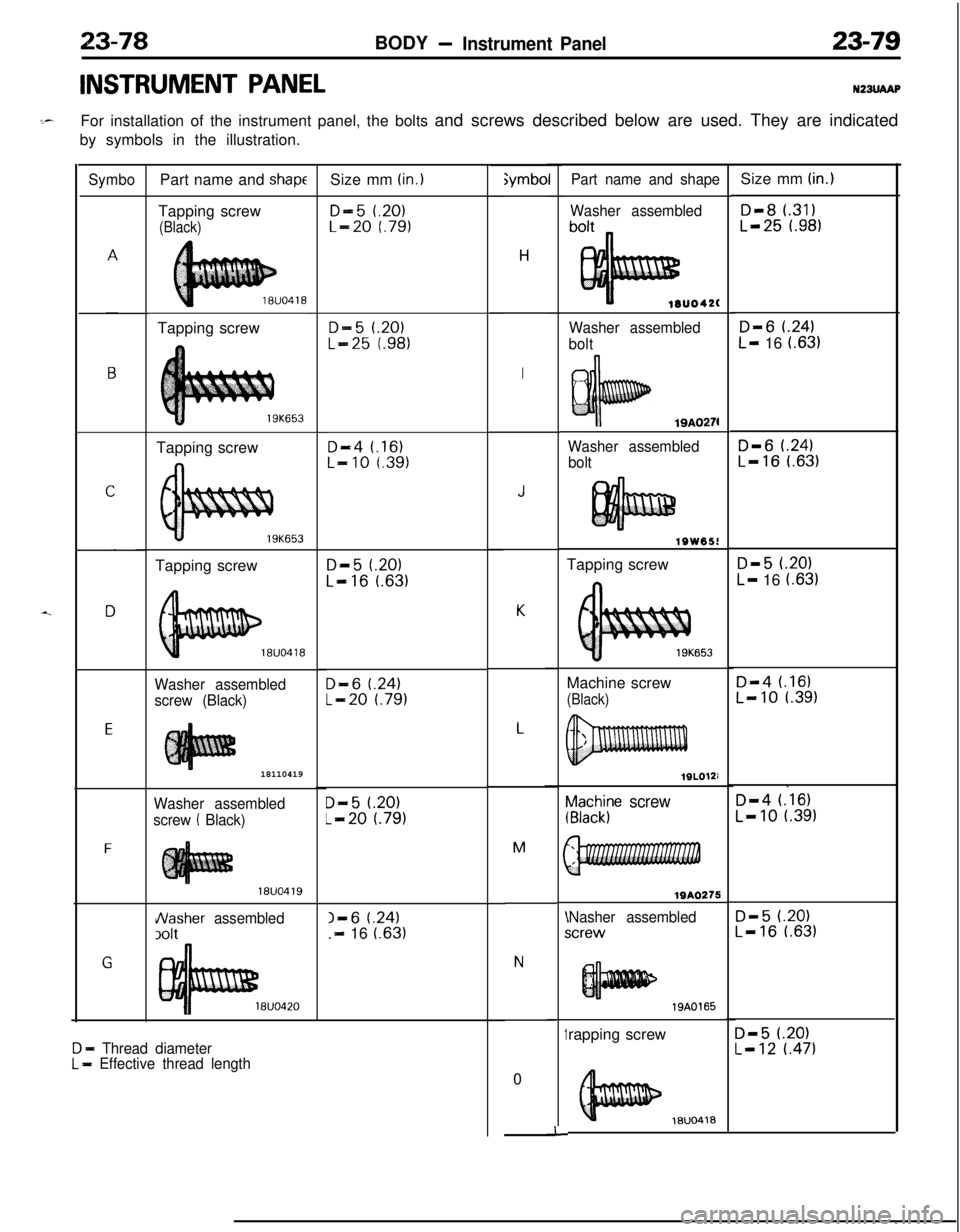
For installation of the instrument panel, the bolts and screws described below are used. They are indicated
by symbols in the illustration.
Symbo
E
F
GPart name and
shapeTapping screw
(Black)Tapping screw
Tapping screw
19K653Tapping screw
Washer assembled
screw (Black)18110419
Washer assembled
screw
! Black)
18UO419
Nasher assembled
3olt
8UO420
D - Thread diameterL = Effective thread lengthSize mm
(in.)
D-5 t.20)L-20 f.79)
D-5 1.20)
L-25 t.98)
D-4 t.16)L-10 r.391
D-5 f.20)
L-16 l.63)
D-6 t.24)
L-20 l.79)
D-5 t.20)
L-20 t.791
I-6 t.24)-=- 16 i.63);ymbo
H
I
J
K
L
M
N0
~a2h$e screw
WA0275
Nasher assembledicrew\I
1
-I-rapping screw
Part name and shape
Washer assembled
lOUO42(
Washer assembled
bolt
19A0274
Washer assembled
bolt
lSW65!Tapping screw
653Machine screw
(Black)
19A0165
18UO418Size mm
(in.)
D-8 l.31)L-25 t.98)
D-6 t.24)
L- 16 (.63)
D-6 f.24)L-16 l.63)
D-5 (.20)
L- 16 i.631
D-4 t.16)L-10 l.39)
D-4 (.‘16)
L-10 t.391
D-5 t.20)L-16 l.63)
D-5 l.20)L-12 t.471
Page 1124 of 1216
23-80BODY - Instrument Panel
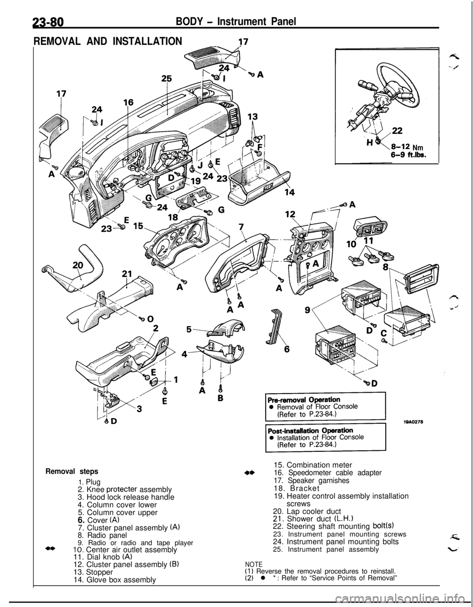
REMOVAL AND INSTALLATION
-?7
Removal steps
1. Plug2. Knee protecter assembly
3. Hood lock release handle
4. Column cover lower
5. Column cover upper
6. Cover
(A)7. Cluster panel assembly (A)8. Radio panel9. Radio or radio and tape player
10. Center air outlet assembly
11. Dial knob (A)12. Cluster panel assembly (B)13. Stopper
14. Glove box assembly
Nm6-9 ft.lk.15. Combination meter
16. Speedometer cable adapter
17. Speaker garnishes18. Bracket
19. Heater control assembly installation
screws
20. Lap cooler duct
21. Shower duct (L.H.122. Steering shaft mounting bolt(s)23. Instrument panel mounting screws
24. Instrument panel mounting bolts
25. Instrument panel assembly
NOTE(1) Reverse the removal procedures to reinstall.(2) l * : Refer to “Service Points of Removal”
Page 1125 of 1216

BODY - Instrument Panel23-81
SECT. A-A
Flat-tip
( - ) screwdriver19A0274
1910267
SERVICE POINTS OF REMOVAL
10. REMOVAL OF CENTER AIR OUTLET ASSEMBLY
Removing the paw1 of the center air outlet assembly with aflat-tip
( - 1 screwdriver,remove the center air outlet
assembly with the plastic trim tool.
16. REMOVAL OF SPEEDOMETER CABLE ADAPTER
(1) Disconnect the speedometer cable at the transaxle endof the cable.
(2) Pull the speedometer cable slightly toward the vehicle
interior, release the lock by turning the adapter to the leftor right, and then remove the adapter.
Page 1126 of 1216
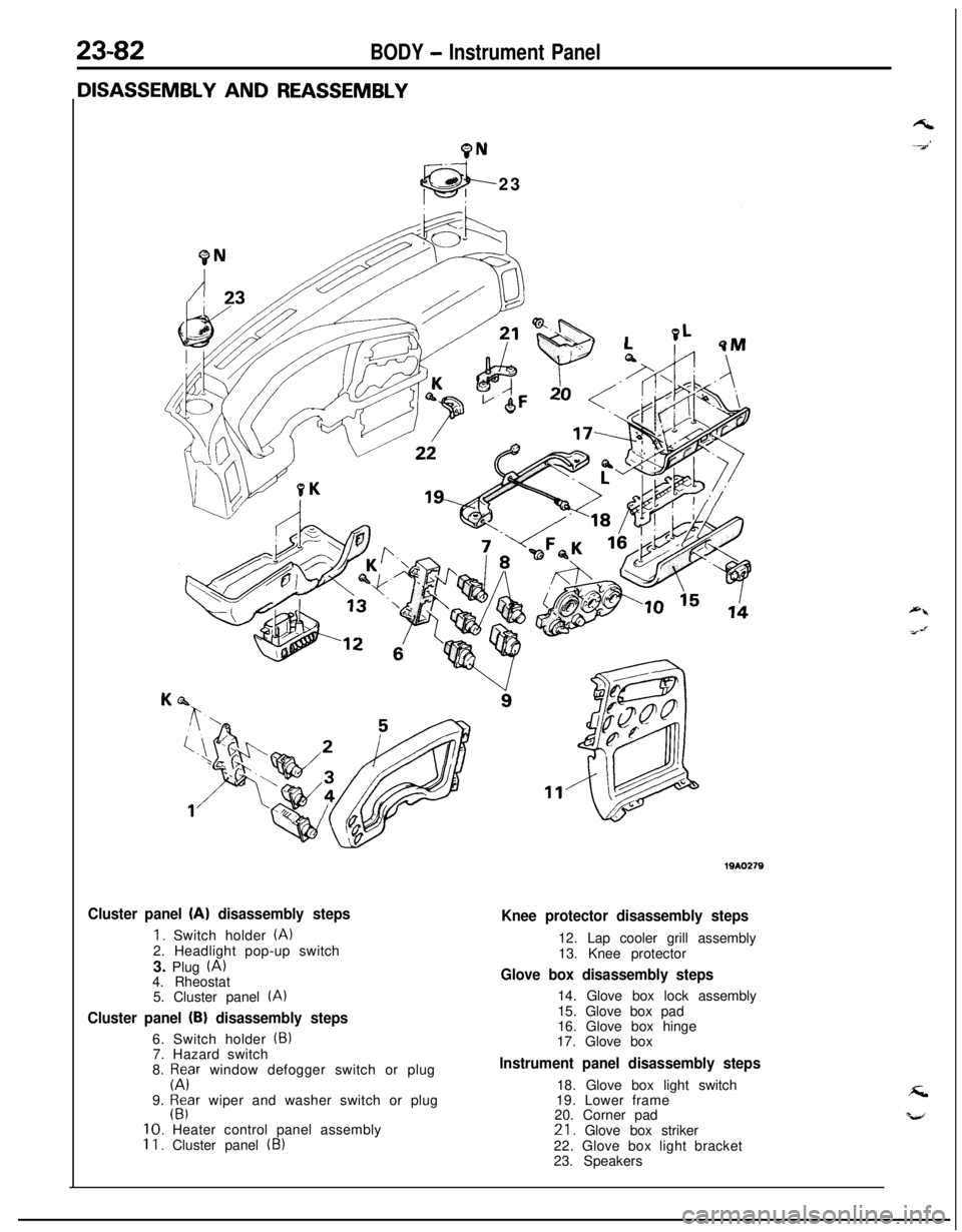
23-82BODY - Instrument Panel
9N23
Cluster panel (A) disassembly steps
1. Switch holder (A)2. Headlight pop-up switch
3. Plug
(A)4. Rheostat
5. Cluster panel
(A)
Cluster panel (B) disassembly steps6. Switch holder
(5)7. Hazard switch
8.
p;Fr window defogger switch or plug
9.
$far wiper and washer switch or plug10. Heater control panel assembly
II. Cluster panel (B)
Knee protector disassembly steps12. Lap cooler grill assembly
13. Knee protector
Glove box disassembly steps14. Glove box lock assembly
15. Glove box pad
16. Glove box hinge
17. Glove box
Instrument panel disassembly steps18. Glove box light switch
19. Lower frame
20. Corner pad21. Glove box striker
22. Glove box light bracket
23. Speakers
Page 1127 of 1216
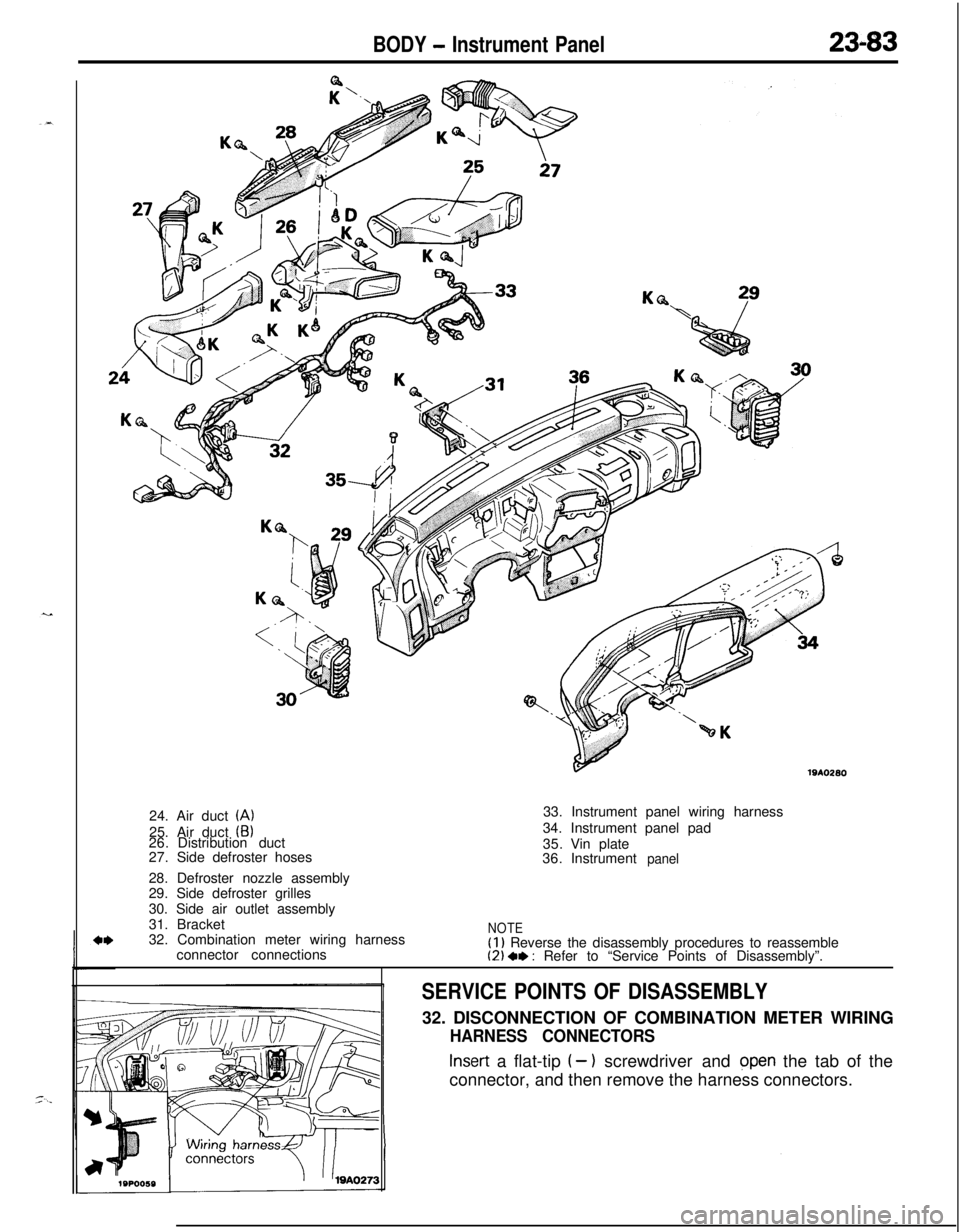
BODY - Instrument Panel23-83
191026024. Air duct
(A)25. Air duct
(B)26.Distribution duct
27.Side defroster hoses
28. Defroster nozzle assembly
29. Side defroster grilles
30. Side air outlet assembly
31. Bracket
32. Combination meter wiring harness
connector connections33. Instrument panel wiring harness
34. Instrument panel pad
35.Vin plate
36.Instrument
panel
NOTE(I) Reverse the disassembly procedures to reassemble(2) 4, : Refer to “Service Points of Disassembly”.
SERVICE POINTS OF DISASSEMBLY32. DISCONNECTION OF COMBINATION METER WIRING
HARNESS CONNECTORS
Insert a flat-tip I- 1 screwdriver and open the tab of the
connector, and then remove the harness connectors.
Page 1128 of 1216
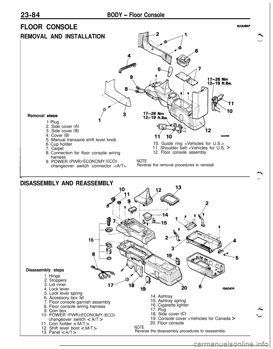
23-84BODY - Floor Console
FLOOR CONSOLEN23lJBAP
REMOVAL AND INSTALLATIONGk2 /---I
Removal stew1 Plug
2. Side cover
(A)3. Side cover (B)4. Cover
(6)5. Manual transaxle shift lever knob
6. Cup holder7. Carpet8. fCor;e~tion for floor console wiring
9. POWER
(PWR)/ECONOMY (EC01changeover switch connector
11'ld19102e1)10. Guide ring
11. Shoulder belt
NOTEReverse the removal procedures to reinstall.
DISASSEMBLY AND REASSEMBLY16
19AO414
Disassembly steps
1. Hinge
2. Stoooers3. Lid ‘inneF4. Lock lever
5. Lock lever spring
6. Accessory box lid
7. Floor console garnish assembly
8. Floor console wiring harness
9. Coin box
10. POWER (PWR)/ECONOMY (ECO)changeover switch < AIT >11. Coin holder < M/T>12. Shift lever boot
15. Ashtray spring
16. Cigarette lighter
17. Plug18. Side cover (C)19. Console cover
NOTEReverse the disassembly procedures to reassemble.
Page 1129 of 1216
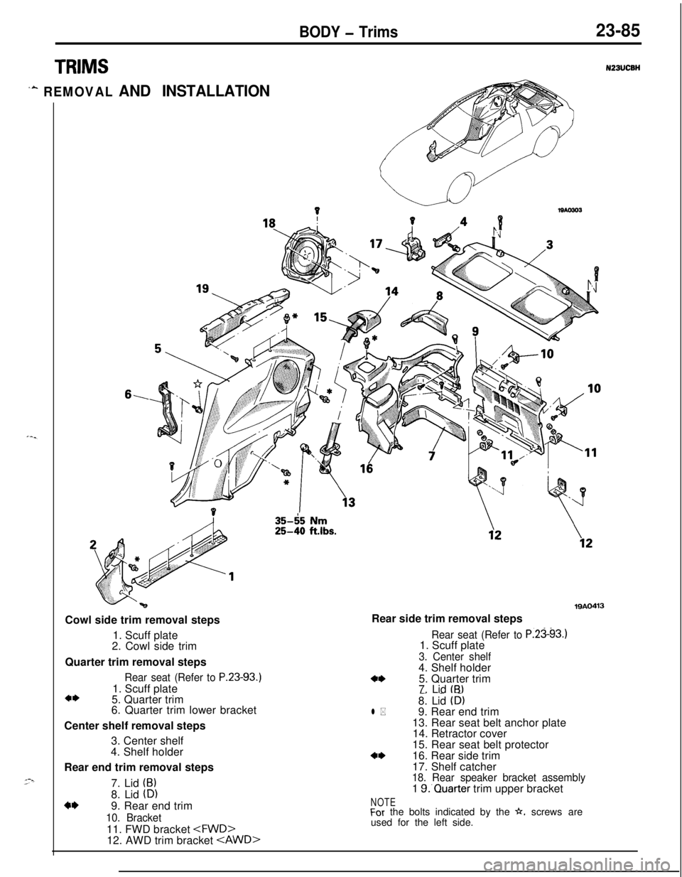
BODY - Trims23-85
TRIMS
‘A REMOVAL AND INSTALLATION
6,Cowl side trim removal steps
1. Scuff plate
2. Cowl side trim
Quarter trim removal steps
Rear seat (Refer to P.23-93.1. Scuff plate
a*5. Quarter trim
6. Quarter trim lower bracket
Center shelf removal steps
3. Center shelf
4. Shelf holder
Rear end trim removal steps
7. Lid
(B)8. Lid
(D)4*9. Rear end trim
10. Bracket11. FWD bracket
35-65 Nm25-40 ftlbs.
19AO413Rear side trim removal steps
Rear seat (Refer to P.2393.11. Scuff plate
3. Center shelf4. Shelf holder
4*5. Quarter trim
7. Lid tB)-. _ -8. Lid (D)l *9. Rear end trim
13. Rear seat belt anchor plate
14. Retractor cover
15. Rear seat belt protector
a*16. Rear side trim
17. Shelf catcher
18. Rear speaker bracket assembly1 S.‘Quarter trim upper bracket
NOTEFor the bolts indicated by the h. screws are
used for the left side.
Page 1130 of 1216
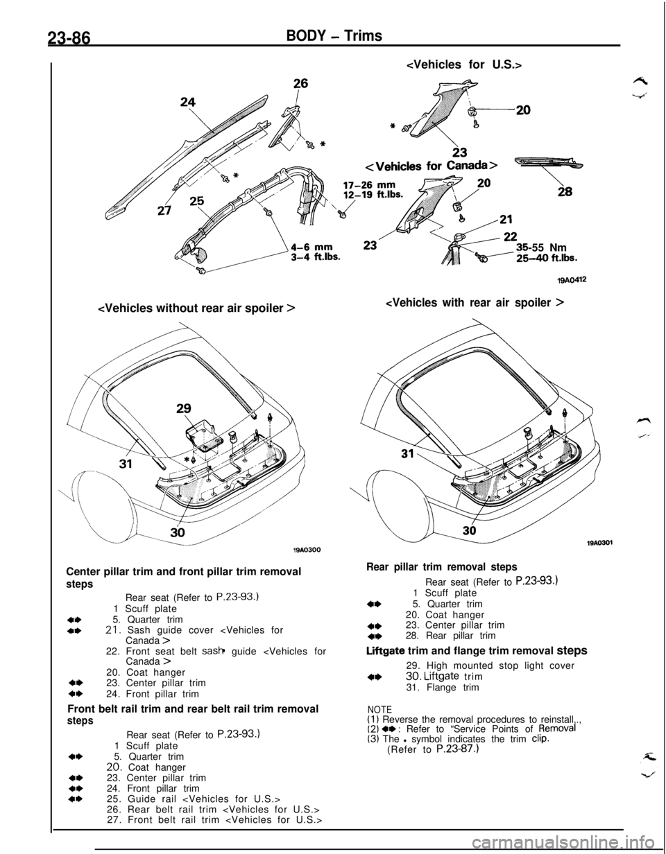
23-86BODY - Trims
-55 Nm
Qi----- %40 ft.lbs.
u.u19AO300
Center pillar trim and front pillar trim removal
steps
404,Rear seat (Refer to P.23-93.)
1 Scuff plate
5. Quarter trim21. Sash guide cover
4,23. Center pillar trimc*24. Front pillar trim
Front belt rail trim and rear belt rail trim removal
steps
4*
4,4*4*Rear seat (Refer to P.23-93.)
1 Scuff plate
5. Quarter trim
20. Coat hanger
23. Center pillar trim
24. Front pillar trim
25. Guide rail
26. Rear belt rail trim
27. Front belt rail trim
19AO412
19AO301
Rear pillar trim removal stepsRear seat (Refer to P.23-93.)
1 Scuff plate
4*5. Quarter trim
20. Coat hanger
4*23. Center pillar trim4*28. Rear pillar trim
Liftgate trim and flange trim removal steps
29. High mounted stop light cover
4*30. Liftgate trim
31. Flange trim
NOTE(1) Reverse the removal procedures to reinstall,.,(2) 4, : Refer to “Service Points of pemoval(3) The l symbol indicates the trim clip.(Refer to P.23-87.)