MITSUBISHI ECLIPSE 1991 Service Manual
Manufacturer: MITSUBISHI, Model Year: 1991, Model line: ECLIPSE, Model: MITSUBISHI ECLIPSE 1991Pages: 1216, PDF Size: 67.42 MB
Page 1091 of 1216
BODY - Garnishes2347
GARNISHES
N2iRW
~w REMOVAL AND INSTALLATIONi‘\
18Ao435
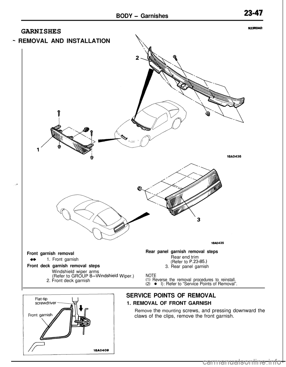
Front garnish removal
4m1. Front garnish
Front deck garnish removal stepsWindshield wiper arms
Rear panel garnish removal stepsRear end trim
(Refer to P.23-85.)
3. Rear panel garnish(Refer to GROUP
8-Windshield Wiper.)
2. Front deck garnishNOTE(1) Reverse the removal procedures to reinstall.(2) l I) : Refer to “Service Points of Removal”.
SERVICE POINTS OF REMOVAL1. REMOVAL OF FRONT GARNISH
Remove the mounting screws, and pressing downward the
claws of the clips, remove the front garnish.
Page 1092 of 1216
23-48
MOULDINGBODY
- Moulding
REMOVAL AND INSTALLATION67 6WA0421
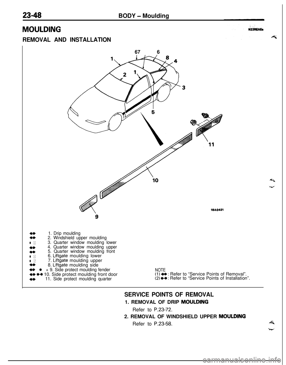
4,1. Drip moulding4,2. Windshield upper moulding
l *3. Quarter window moulding lower
**4. Quarter window moulding upper
4*5. Quarter window moulding front
l *6. Liftgate moulding lower
l +7. Liftgate moulding uppera*8. Liftgate moulding side
+* l + 9. Side protect moulding fender
+e I)+ 10. Side protect moulding front door
4,11. Side protect moulding quarter
NOTE(1) ** : Refer to “Service Points of Removal”.(2) I)+ : Refer to “Service Points of Installation”.
SERVICE POINTS OF REMOVAL1. REMOVAL OF DRIP MOULDING
Refer to
P.23-72.2. REMOVAL OF WINDSHIELD UPPER
MOULDINGRefer to
P.23-58.
Page 1093 of 1216
BODY - Moulding23-493.
REMOVAL OF QUARTER WINDOW MOULDING LOWER/
4. QUARTER WINDOW MOULDING UPPER/B. QUARTERWINDOW MOULDING FRONT
Refer to
P.23-61.6. REMOVAL OF
LIFTGATE MOULDING LOWERI7. LIFT-GATE MOULDING
UPPER/8. LIFTGATE MOULDING
SIDERefer to
P.23-62.
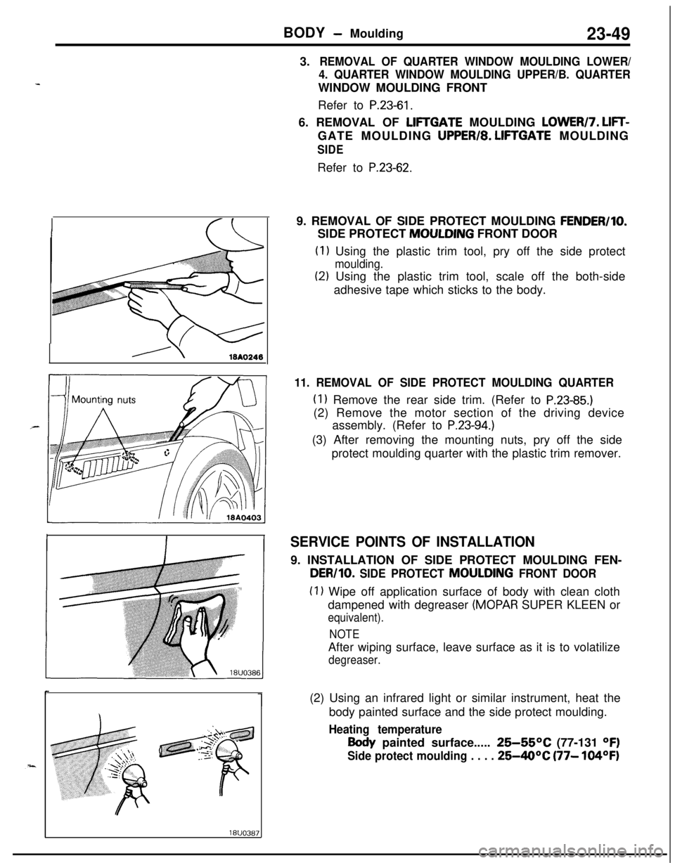
19. REMOVAL OF SIDE PROTECT MOULDING
FENDER/IO.SIDE PROTECT MOULDING FRONT DOOR
(1) Using the plastic trim tool, pry off the side protect
moulding.
(2) Using the plastic trim tool, scale off the both-side
adhesive tape which sticks to the body.
11. REMOVAL OF SIDE PROTECT MOULDING QUARTER
(1) Remove the rear side trim. (Refer to P.23-85.)(2) Remove the motor section of the driving device
assembly. (Refer to
P.23-94.)(3) After removing the mounting nuts, pry off the side
protect moulding quarter with the plastic trim remover.
SERVICE POINTS OF INSTALLATION9. INSTALLATION OF SIDE PROTECT MOULDING FEN-
DER/10. SIDE PROTECT MOULDING FRONT DOOR
(1) Wipe off application surface of body with clean cloth
dampened with degreaser
(MOPAR SUPER KLEEN or
equivalent).
NOTEAfter wiping surface, leave surface as it is to volatilize
degreaser.(2) Using an infrared light or similar instrument, heat the
body painted surface and the side protect moulding.
Heating temperature
Body painted surface..... 25-55OC (77-131 OF)
Side protect moulding . . . . 25-40°C (77- 104OF)
Page 1094 of 1216
23-50BODY - Moulding
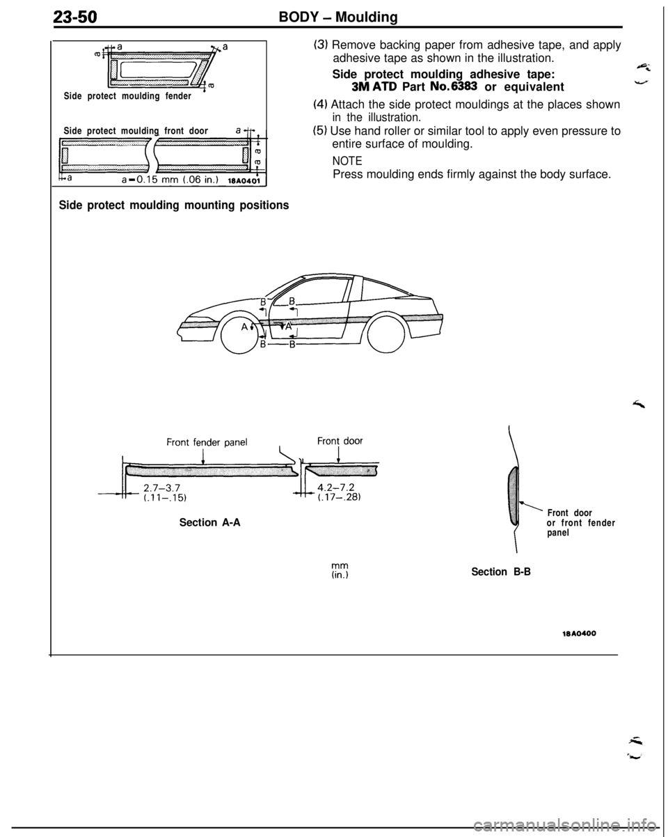
Side protect moulding fender
’Side protect moulding front door
Side protect moulding mounting positions
(3) Remove backing paper from adhesive tape, and apply
adhesive tape as shown in the illustration.
Side protect moulding adhesive tape:
6
3M ATD Part No.6383 or equivalentV
(4) Attach the side protect mouldings at the places shown
in the illustration.
(5) Use hand roller or similar tool to apply even pressure to
entire surface of moulding.
NOTEPress moulding ends firmly against the body surface.
Section A-AFront door
or front fender
ipanel
Section B-BWA0400
Page 1095 of 1216
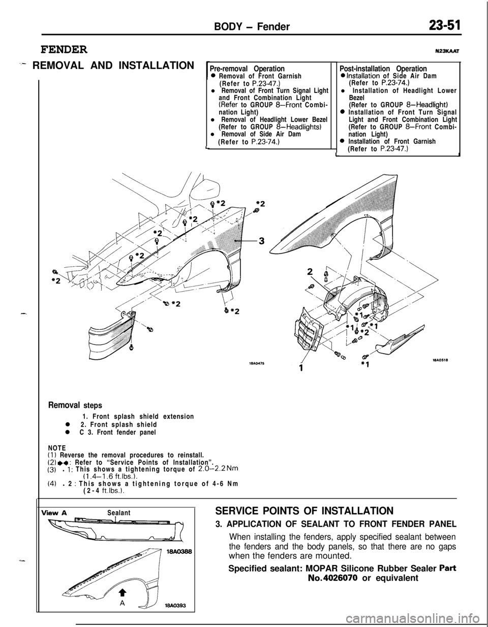
BODY - Fender
FENDER
:- REMOVAL AND INSTALLATION
-.
Pre-removal Operation0 Removal of Front Garnish
(Refer to P.23-47.)l Removal of Front Turn Signal Light
and Front Combination Light
(Refer to GROUP 8-Front Combi-
nation Light)
l Removal of Headlight Lower Bezel
(Refer to GROUP
8-Headlights)l Removal of Side Air Dam
(Refer to
P.23-74.)LLu23KAAr
Post-installation Operation0 Installation of Side Air Dam
(Refer to P.23-74.)l Installation of Headlight Lower
Bezel
(Refer to GROUP
8-Headlight)0 Installation of Front Turn Signal
Light and Front Combination Light
(Refer to GROUP
8-Front Combi-
nation Light)
0 Installation of Front Garnish
(Refer to P.23-47.)J
Removal steps1. Front splash shield extension
l 2. Front splash shield
l C 3. Front fender panel
NOTE
(1) Reverse the removal procedures to reinstall.(2) .a : Refer to “Service Points of Installation”.
(3)l 1 : This shows a tightening torque of 2.0-2.2 Nm(1 .4-l .6 ft.lbs.1.(4)l 2 : This shows a tightening torque of 4-6 Nm
(2-4 ft.lbs.1.
View ASealantSERVICE POINTS OF INSTALLATION
3. APPLICATION OF SEALANT TO FRONT FENDER PANEL
When installing the fenders, apply specified sealant between
the fenders and the body panels, so that there are no gapswhen the fenders are mounted.
Specified sealant: MOPAR Silicone Rubber Sealer
PartNo.4026070 or equivalent
Page 1096 of 1216
23-52BODY - Fender
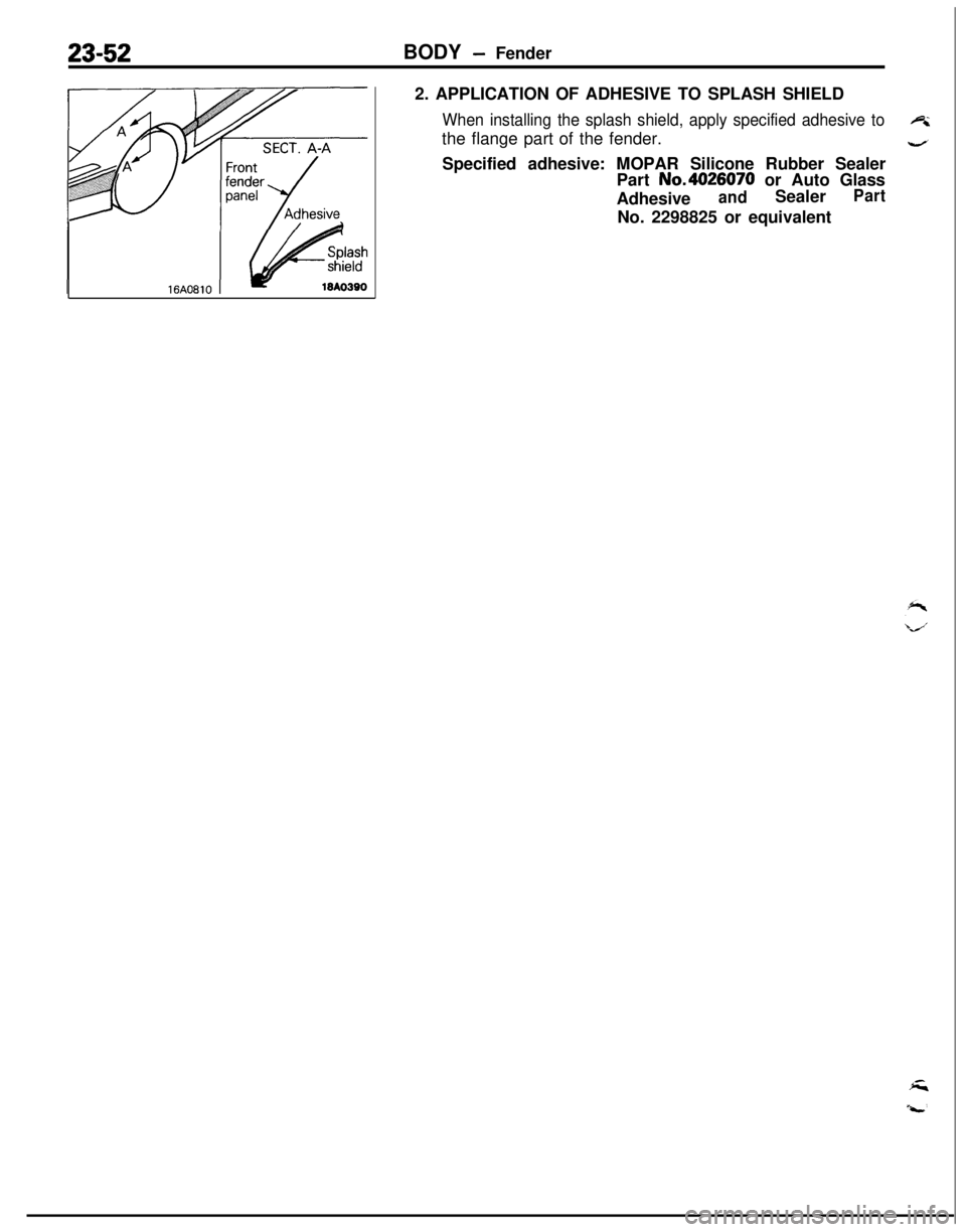
2. APPLICATION OF ADHESIVE TO SPLASH SHIELD
When installing the splash shield, apply specified adhesive toethe flange part of the fender.
4Specified adhesive: MOPAR Silicone Rubber Sealer
Part No.4026070 or Auto Glass
Adhesive
andSealerPartNo. 2298825 or equivalent
Page 1097 of 1216
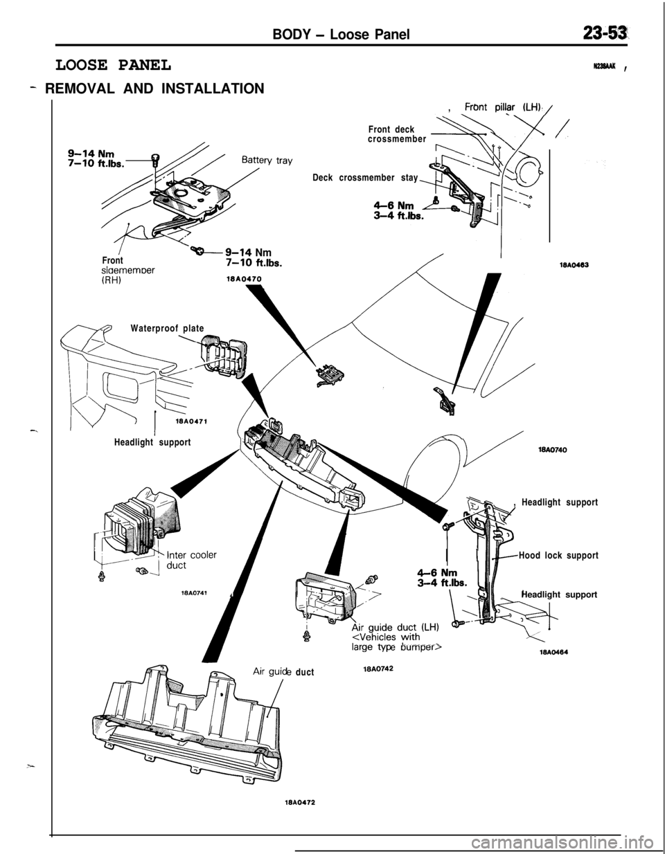
BODY - Loose Panel
LOOSE PANEL
- REMOVAL AND INSTALLATION
, Frbnt
piI@ (LH),/
N22SAAK ,
-.
v trayFront deck
crossmember
+ADeck crossmember stay
/Front
I
‘-9-14 Nm7-10 ftlbs.slaememoer
mWaterproof plate\K?%--
(RH)
WA0471Headlight supportWA.0741
,
/
WA0463, Headlight support
/-c---x/
I IHood lock support
_Headlight supporte duct
MA0742
WA0472
e Dumper,18AO484
Page 1098 of 1216
23-54BODY - Window Glass
WINDOW GLASS
N23LAAB
GENERALThe windshield and
liftgate window glass are attached by an urethane-base adhesive to the window frame.
This adhesive not only provides improved glass holding and sealing, but also permits use of body openings
having a greater
structural strength.
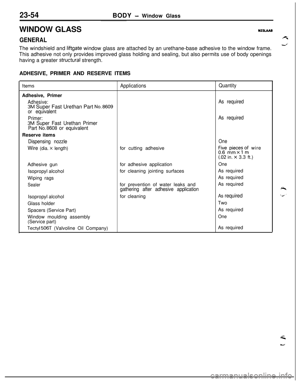
ADHESIVE, PRIMER AND RESERVE ITEMSItems
ApplicationsQuantityAdhesive, Primer
Adhesive:As required
3M Super Fast Urethan Part No.8609
or equivalent
Primer:As required
3M Super Fast Urethan Primer
Part
No.8608 or equivalentReserve items
Dispensing nozzleOne
Wire (dia. x length)for cutting adhesiveLir,“$c;s onfi wire(62 in.
x 3.3 ft.)
Adhesive gunfor adhesive application
OneIsopropyl alcoholfor cleaning jointing surfacesAs required
Wiping ragsAs required
Sealerfor prevention of water leaks andAs requiredgathering after adhesive applicationIsopropyl alcoholfor cleaning
As requiredGlass holderTwo
Spacers (Service Part)As required
Window moulding assembly
One(Service part)
Tectyl 506T (Valvoline Oil Company)As required
Page 1099 of 1216
BODY - Window Glass23-55
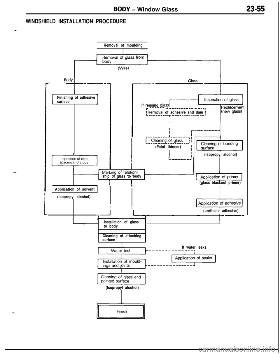
WINDSHIELD INSTALLATION PROCEDURE
_-Body
--
+
e-eRemoval of moulding
(Wire)
IFinishing of adhesive
surfaceGlass-tIf reusing glass;
r --------- 1 ---s------ - -‘-,
IRemoval of adhesive and dam rL---------r---s---------- I
e-e _---mm,- __-_--_ 1,(Paint thinner)
II
IIIship ofglass tobody
IApplication of solvent
(Isopropyl alcohol)
III
-*I(Isopropyl alcohol)
(glass blackout primer)
pi&g(urethane adhesive)
-1 I- - -Installation of glass
_to body
ICleaning of attaching
surface
1If water leaks
--------------~
p%zG&pJ(Isopropyl alcohol)
Page 1100 of 1216
23-56BODY - Window Glass
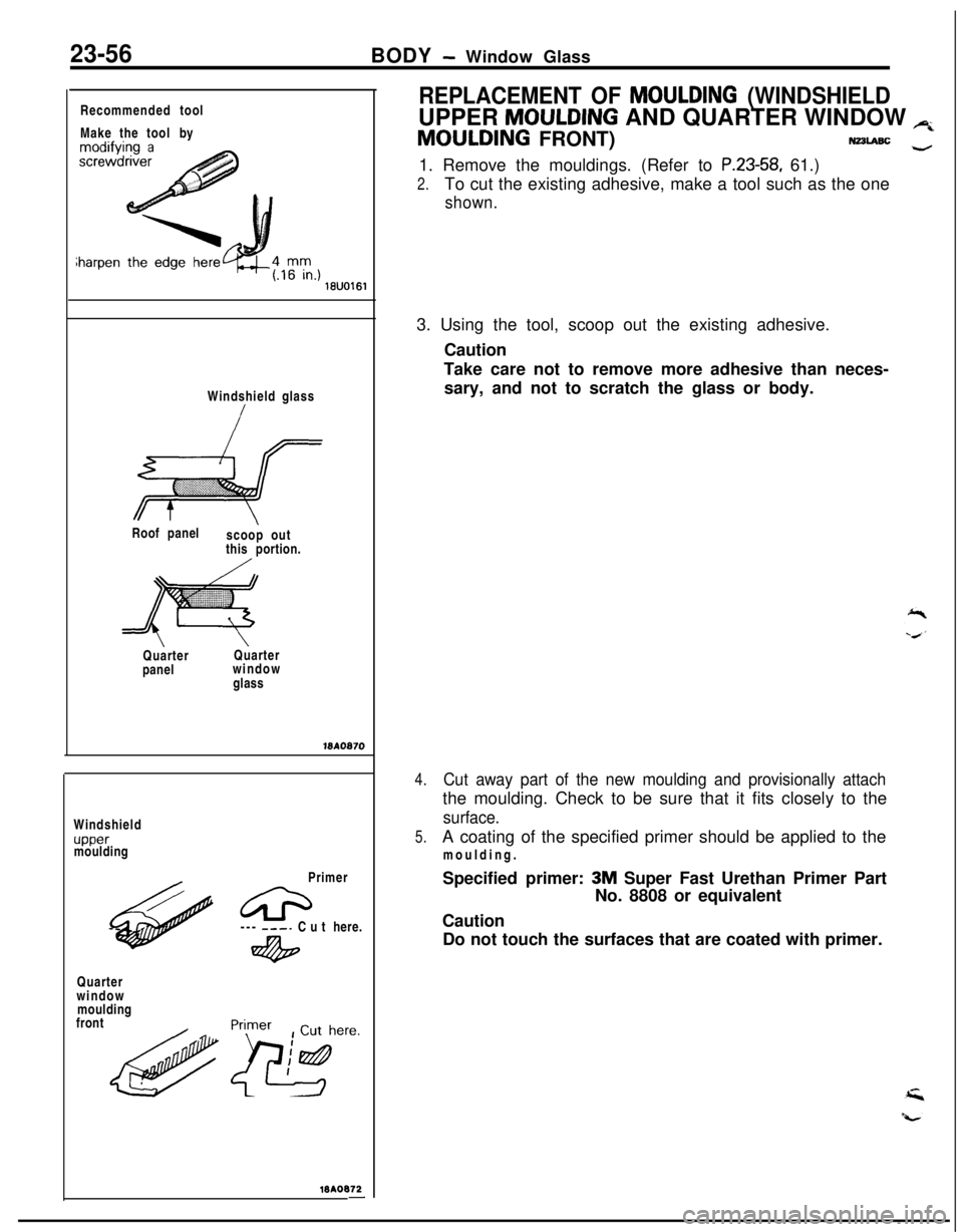
Recommended tool
Make the toolby
Windshield glass
Roof panel
scoop out
this portion.
iiiii- ,.:::i:::::::::::i.p:://jiiiig;iiiijjiiij
I&
::::::::::iiiiiii.::;QuarterQuarter
panelwindow
glass
WA0870Windshield
uppermoulding
Primer
Quarter
window
moulding
front---
---. Cuthere.
4%
>/yere.
MAO672-
REPLACEMENT OF MOULDING (WINDSHIELDUPPER
MOULDING AND QUARTER WINDOW p;MOULDING FRONT)
N22LABc -1. Remove the mouldings. (Refer to
P.23-58, 61.)
2.To cut the existing adhesive, make a tool such as the one
shown.3. Using the tool, scoop out the existing adhesive.
Caution
Take care not to remove more adhesive than neces-
sary, and not to scratch the glass or body.
4.Cut away part of the new moulding and provisionally attachthe moulding. Check to be sure that it fits closely to the
surface.
5.A coating of the specified primer should be applied to the
moulding.
Specified primer:
3M Super Fast Urethan Primer Part
No. 8808 or equivalent
Caution
Do not touch the surfaces that are coated with primer.