MITSUBISHI ECLIPSE 1991 Service Manual
Manufacturer: MITSUBISHI, Model Year: 1991, Model line: ECLIPSE, Model: MITSUBISHI ECLIPSE 1991Pages: 1216, PDF Size: 67.42 MB
Page 1111 of 1216
BODY - Door Glass and Reaulator/Power Window23-67
POWER WINDOW
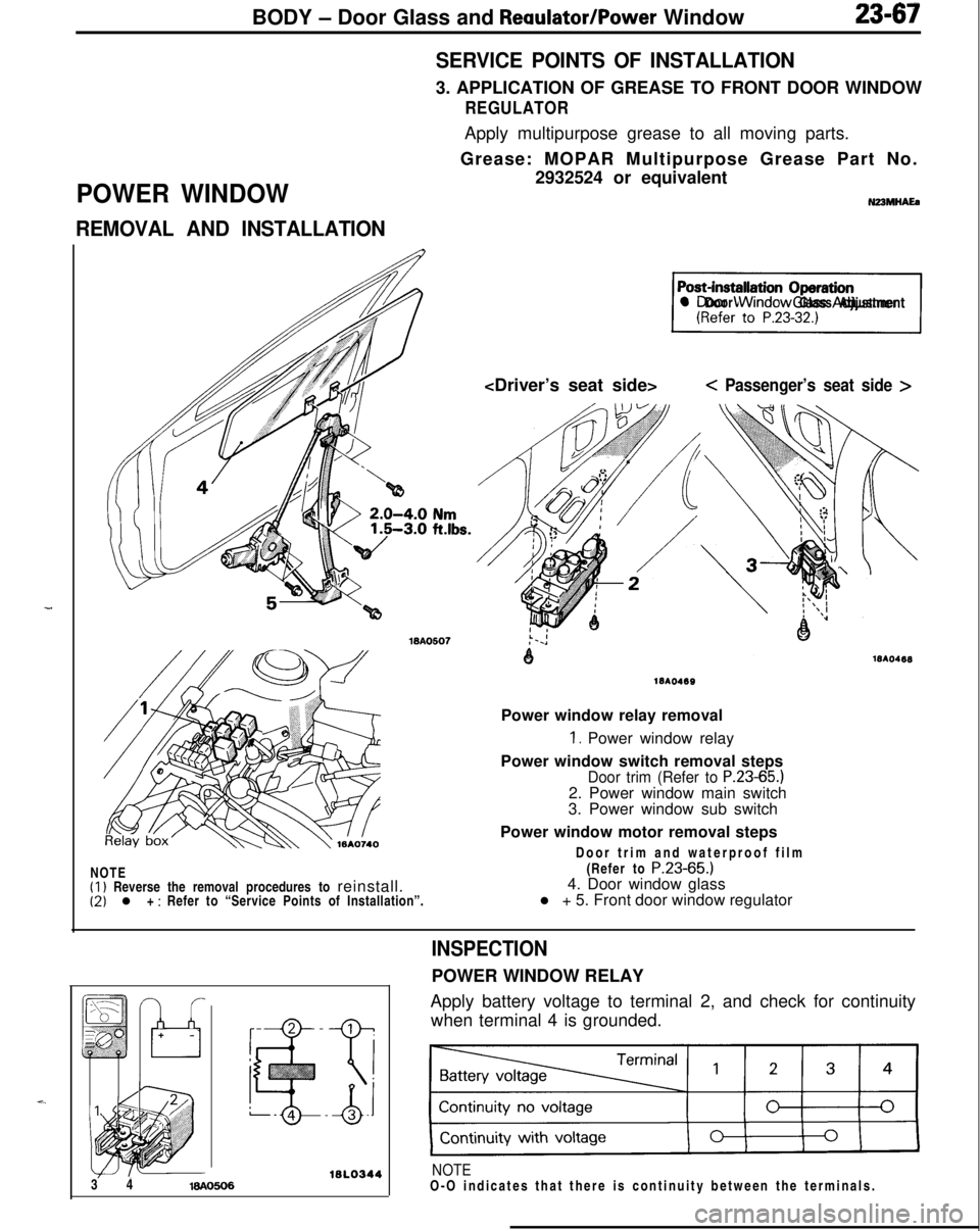
REMOVAL AND INSTALLATIONSERVICE POINTS OF INSTALLATION3. APPLICATION OF GREASE TO FRONT DOOR WINDOW
REGULATORApply multipurpose grease to all moving parts.
Grease: MOPAR Multipurpose Grease Part No.
2932524 or equivalent
N23MHAEa
71l Door Window Glass Adjustment
< Passenger’s seat side >NOTE
(1) Reverse the removal procedures to reinstall.(2) l + : Refer to “Service Points of Installation”.
1810469Power window relay removal
1. Power window relay
Power window switch removal steps
Door trim (Refer to P.23-65.)2. Power window main switch
3. Power window sub switch
Power window motor removal steps
Door trim and waterproof film
(Refer to
P.23-65.)4. Door window glass
l + 5. Front door window regulator
16l.03443 416AO606
INSPECTIONPOWER WINDOW RELAY
Apply battery voltage to terminal 2, and check for continuity
when terminal 4 is grounded.
NOTEO-O indicates that there is continuity between the terminals.
Page 1112 of 1216
23-68BODY - Power Window
Power
window
lock
switch
,POWER WINDOW MOTOR
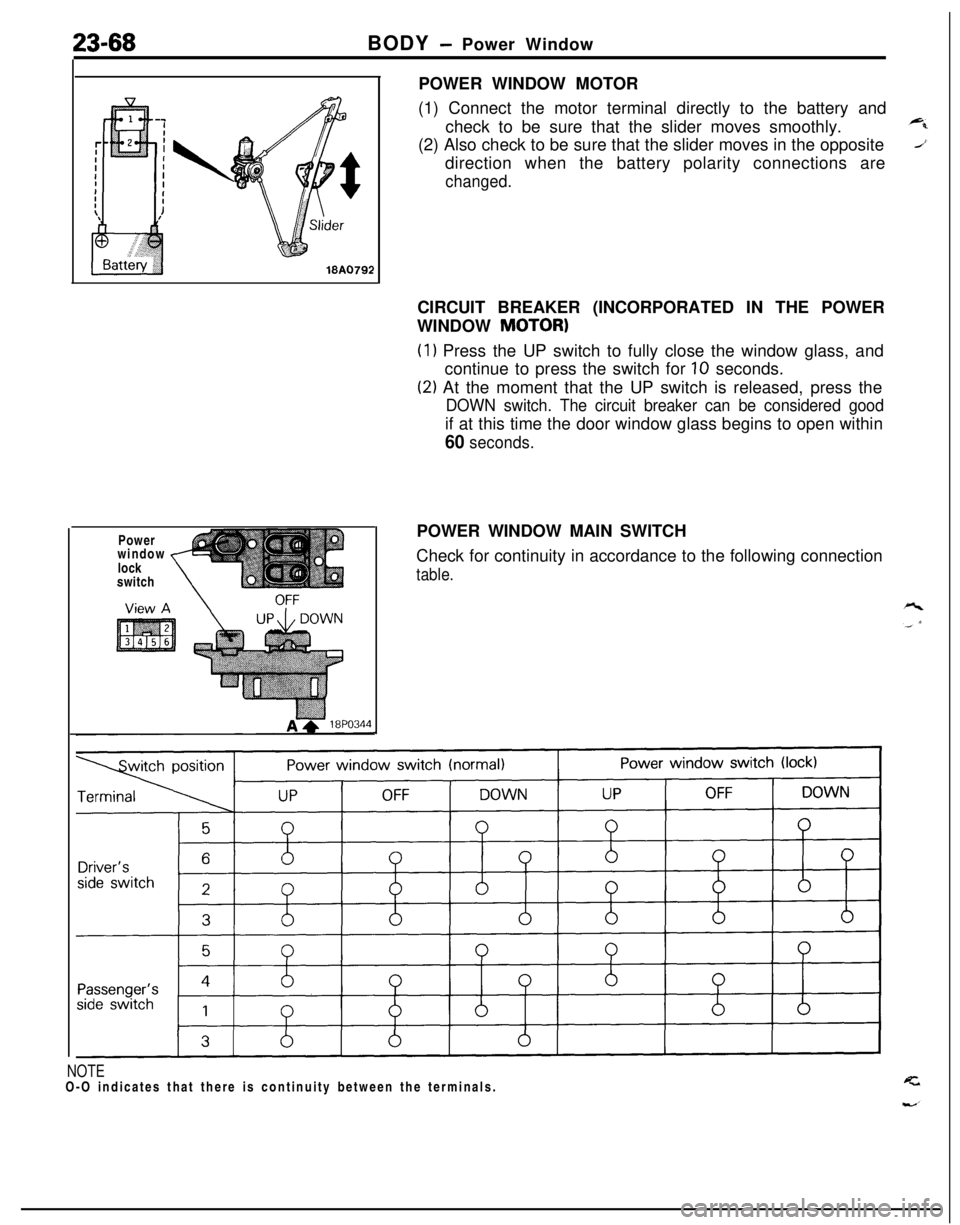
(1) Connect the motor terminal directly to the battery and
check to be sure that the slider moves smoothly.
(2) Also check to be sure that the slider moves in the opposite
direction when the battery polarity connections are
changed.CIRCUIT BREAKER (INCORPORATED IN THE POWER
WINDOW
MOTOR)
(1) Press the UP switch to fully close the window glass, and
continue to press the switch for
10 seconds.
(2) At the moment that the UP switch is released, press the
DOWN switch. The circuit breaker can be considered goodif at this time the door window glass begins to open within
60 seconds.POWER WINDOW MAIN SWITCH
Check for continuity in accordance to the following connection
table.
NOTEO-O indicates that there is continuity between the terminals.
Page 1113 of 1216
BODY - Power Window/Door Handle and Latch23-69
I-
DOOR HANDLE AND LATCHPOWER WINDOW SUB SWITCH
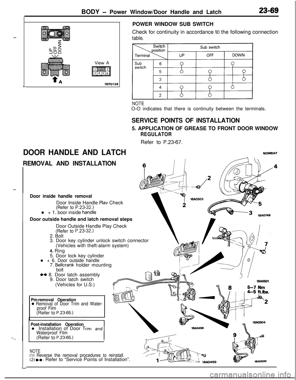
Check for continuity in accordance
10 the following connection
table.
NOTEO-O indicates that there is continuity between the terminals.
SERVICE POINTS OF INSTALLATION5. APPLICATION OF GREASE TO FRONT DOOR WINDOW
REGULATORRefer to
P.23-67.
N23MDAY
REMOVAL AND INSTALLATIONc
Door inside handle removalDoor Inside Handle
Plav Check(Refer to P.23-32.1l + 1. boor inside
handieDoor outside handle and latch removal steps
LDoor Outside Handle Play Check
(Refer to P.23-32.)2. Bolt
3. Door key cylinder unlock switch connector
(Vehicles with theft-alarm system)
4. Ring
5. Door lock key cylinder
l + 6. Door outside handle7. Bellcrank holder mountingbolt
.a 8. Door latch assembly
9. Door latch switch
(Vehicles for U.S.)
Pm-removal Operation0 Removal of Door Trim and Water-
proof Film(Refer to
P.23-65.)
Post-installation Operationl Installation of Door Trim and
1
Waterproof Film(Refer to P.23-65.)
NOTE(I)
Reverse the removal procedures to reinstall.‘/(2) *+ : Refer to “Service Points of Installation”.1m
Page 1114 of 1216
23-70BODY- Door Handle and Latch/Central Door Lockina Svstem
I18AO750 1lBY3611 I.- .--,
!-
II
T!3123
18PO39i
INSPECTIONDOOR KEY CYLINDER UNLOCK SWITCH
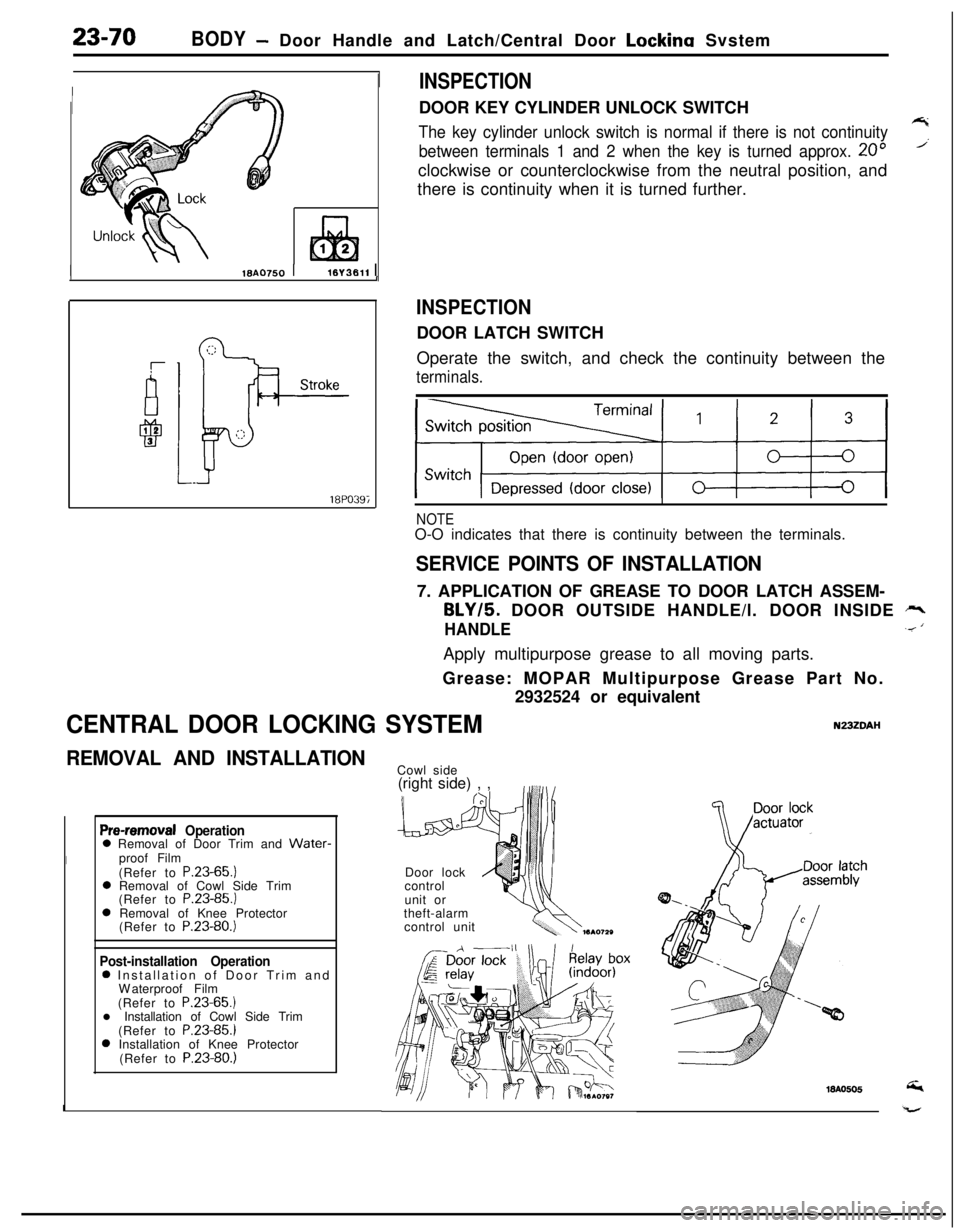
The key cylinder unlock switch is normal if there is not continuity7
between terminals 1 and 2 when the key is turned approx. 20”’clockwise or counterclockwise from the neutral position, and
there is continuity when it is turned further.
INSPECTIONDOOR LATCH SWITCH
Operate the switch, and check the continuity between the
terminals.
NOTEO-O indicates that there is continuity between the terminals.
SERVICE POINTS OF INSTALLATION7. APPLICATION OF GREASE TO DOOR LATCH ASSEM-
BLY/5. DOOR OUTSIDE HANDLE/l. DOOR INSIDE rr,
HANDLE.< ‘Apply multipurpose grease to all moving parts.
Grease: MOPAR Multipurpose Grease Part No.
2932524 or equivalent
CENTRAL DOOR LOCKING SYSTEMN23ZDAI-I
REMOVAL AND INSTALLATION
Pre-removal Operation0 Removal of Door Trim and Water-
Iproof Film
(Refer to P.23-65.)
0 Removal of Cowl Side Trim
(Refer to P.23-85.)
0 Removal of Knee Protector
(Refer to P.23-80.)
Post-installation Operation0 Installation of Door Trim and
Waterproof Film
(Refer to P.23-65.)
l Installation of Cowl Side Trim
(Refer to P.23-85.)
0 Installation of Knee Protector
(Refer to P.23-80.)
ICowl side
(right side) , ,
Door lock
control
unit or
theft-alarm
control unit
Page 1115 of 1216
BODY - Central Door Locking System/Door Runchannel23-71View A
18A0064-
L
DOOR RUNCHANNEL
REMOVAL AND INSTALLATION
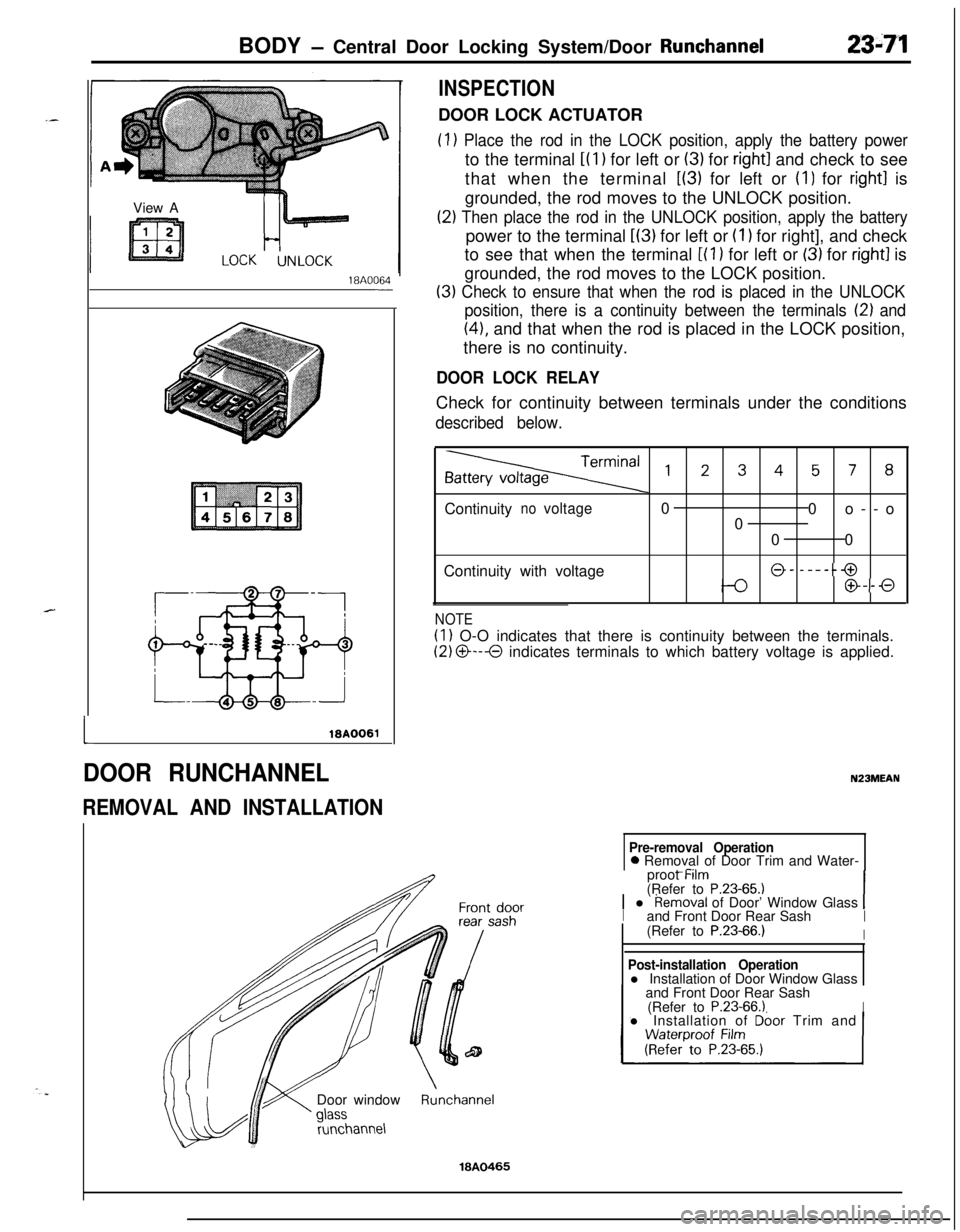
INSPECTIONDOOR LOCK ACTUATOR
(1) Place the rod in the LOCK position, apply the battery powerto the terminal
i(l) for left or (3) for right1 and check to see
that when the terminal
L(3) for left or (I) for right1 is
grounded, the rod moves to the UNLOCK position.
(2) Then place the rod in the UNLOCK position, apply the batterypower to the terminal
L(3) for left or (I 1 for right], and check
to see that when the terminal
[(l ) for left or (3) for right1 is
grounded, the rod moves to the LOCK position.
(3) Check to ensure that when the rod is placed in the UNLOCK
position, there is a continuity between the terminals
12) and
(41, and that when the rod is placed in the LOCK position,
there is no continuity.
DOOR LOCK RELAYCheck for continuity between terminals under the conditions
described below.
,2345, 8Continuity
novoltage0
0o--o
0
00
Continuity with voltage
@- -----@
@--0
NOTE
(1) O-O indicates that there is continuity between the terminals.
(2) O---O indicates terminals to which battery voltage is applied.
N23MEAN
Pre-removal Operation0 Removal of Door Trim and Water-
_ -..proot Mm
(Refer to
P.23-65.11 l Removal of Door’ Window Glass 1Iand Front Door Rear SashI(Refer to P.23-66.)IDoor window
runchannel
Post-installation Operationl Installation of Door Window Glass
and Front Door Rear Sash
(Refer to
P.23-66.1Il Installation of Dbor Trim and
Runchannel
18A0465
Page 1116 of 1216
23-72BODY -Door Moulding and Drip Line Weatherstrip/Door Mirror
DOOR MOULDING AND DRIP LINE WEATHERSTRIPNZBMFAK
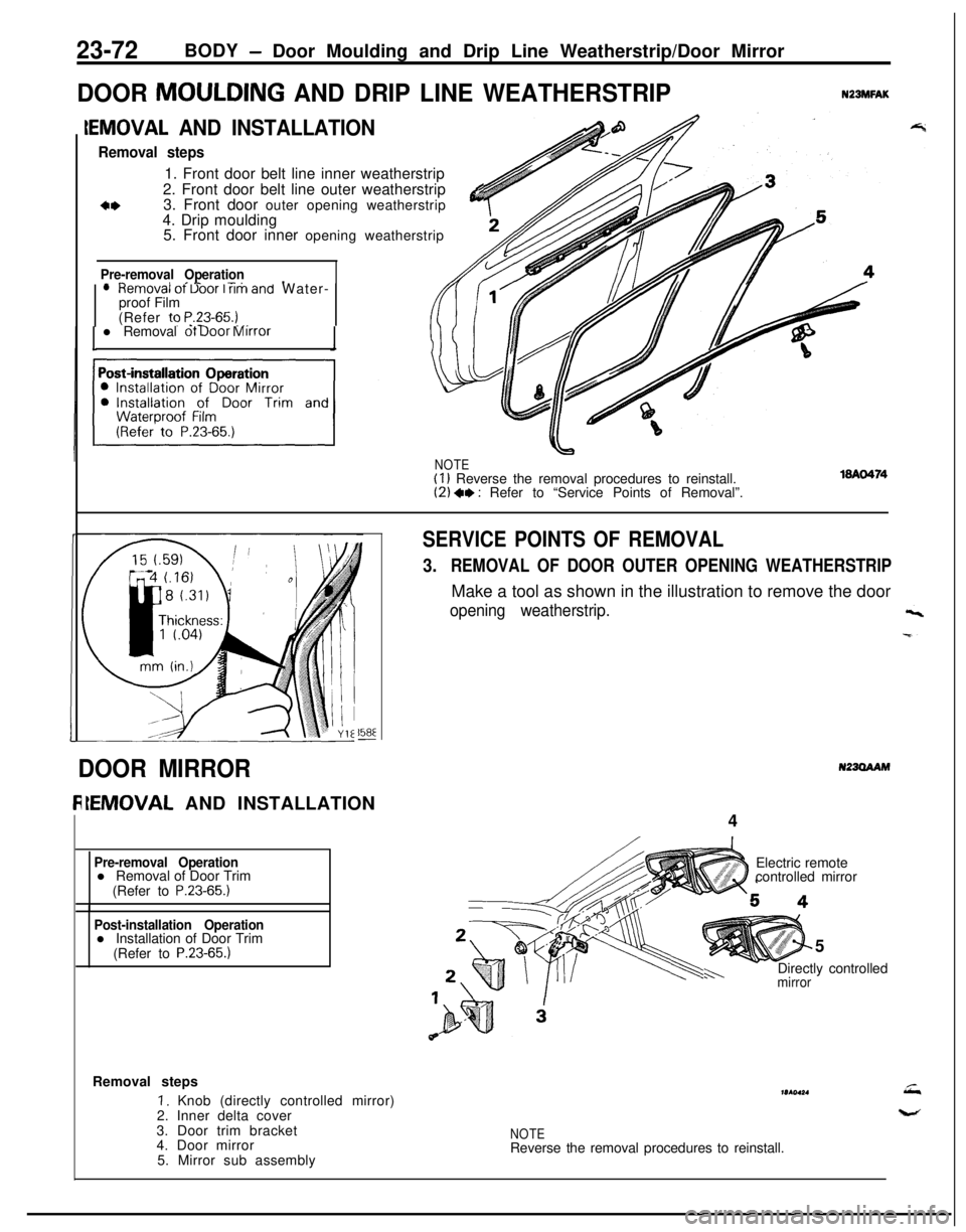
IEMOVAL AND INSTALLATION
Removal steps1. Front door belt line inner weatherstrip
2. Front door belt line outer weatherstrip
3. Front door outer opening weatherstrip
&4. Drip moulding
5. Front door inner opening weatherstrip
Pre-removal Operation- ^II_ -..lHemOVal ot Uoor I rim and Water-
proof Film
(Refer to
P.23-65.) _,. -l Removal ot Door Mirror
NOTE(I 1 Reverse the removal procedures to reinstall.(2) +, : Refer to “Service Points of Removal”.
158E-
SERVICE POINTS OF REMOVAL
3.REMOVAL OF DOOR OUTER OPENING WEATHERSTRIPMake a tool as shown in the illustration to remove the door
opening weatherstrip.
N23OAAMDOOR MIRROR
IEMOVAL AND INSTALLATION
4
Pre-removal Operationl Removal of Door Trim
(Refer to
P.23-65.)
Post-installation Operationl Installation of Door Trim
(Refer to
P.23-65.)5
mirrorh-.Directly controlled Electric remote
controlled mirror
Removal steps
I. Knob (directly controlled mirror)
2. Inner delta cover
3. Door trim bracket
4. Door mirror
5. Mirror sub assemblymr(ol*.
NOTEReverse the removal procedures to reinstall.
Page 1117 of 1216
BODY - Door Mirror/Electric Remote Controlled Mirror Switch23-73
18AO425
16P0109-
INSPECTION
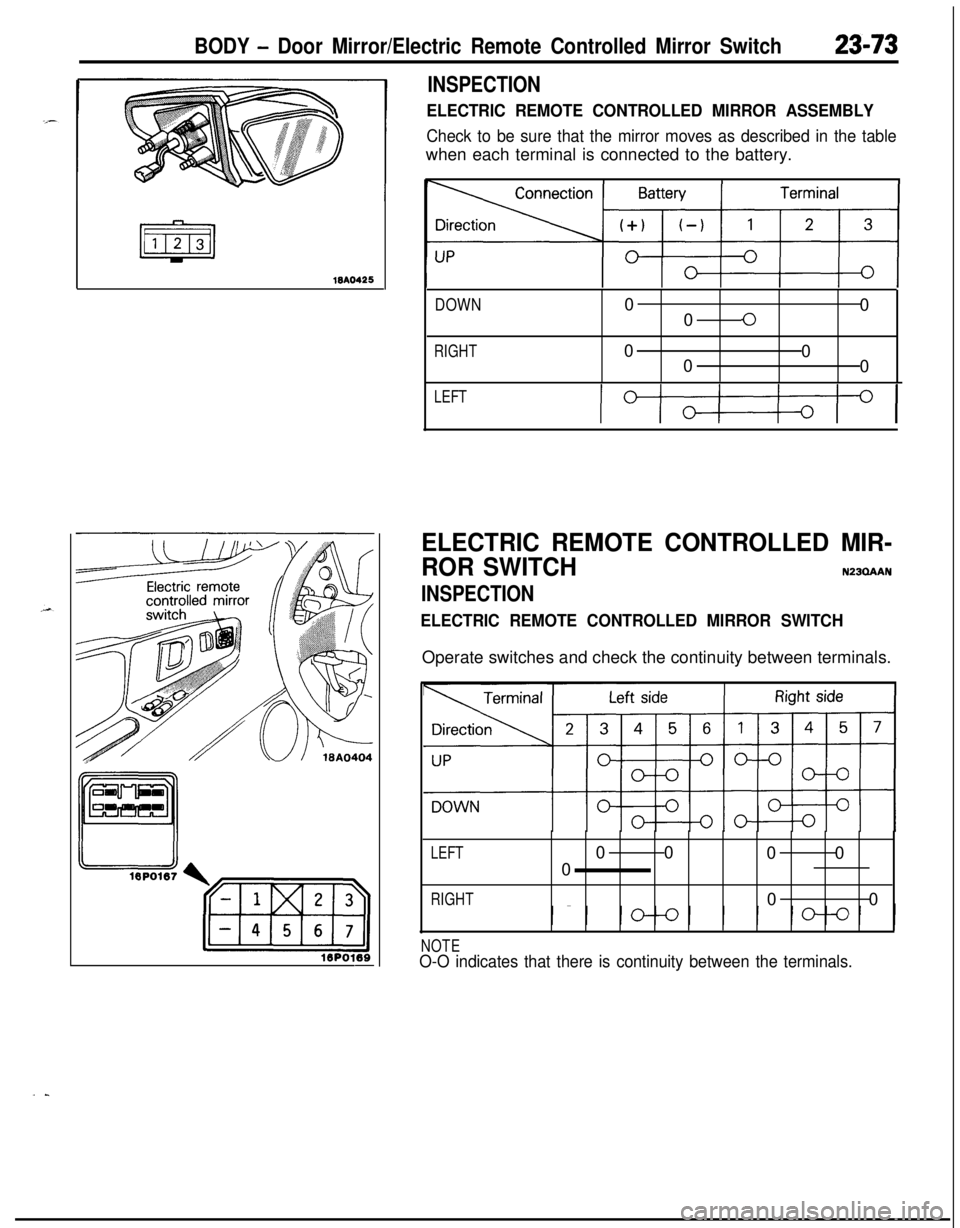
ELECTRIC REMOTE CONTROLLED MIRROR ASSEMBLY
Check to be sure that the mirror moves as described in the tablewhen each terminal is connected to the battery.
DOWN0
0
00
RIGHT0
0
0
0
LEFT
IOI
ELECTRIC REMOTE CONTROLLED MIR-
ROR SWITCH
N23QAAN
INSPECTION
ELECTRIC REMOTE CONTROLLED MIRROR SWITCHOperate switches and check the continuity between terminals.
LEFT00
00
0
RIGHT00
NOTEO-O indicates that there is continuity between the terminals.
..
Page 1118 of 1216
23-74BODY - Aero Parts
AERO PARTSN23XAAH
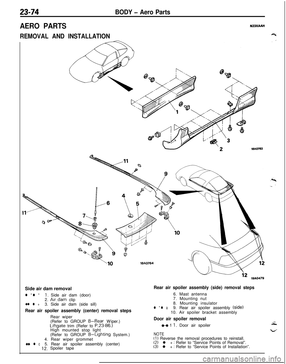
REMOVAL AND INSTALLATION
WA076318A0764
lQA0479Side air dam removal
l * l *1. Side air dam (door)
2. Air,dam clip+* l +3. Side air dam (side sill)
Rear air spoiler assembly (center) removal stepsRear wiper
(Refer to GROUP
8-Rear Wiper.)Liftgate trim (Refer to P.23-86.)
High mounted stop light
(Refer to GROUP
8-Lighting System.)
4. Rear wiper grommet
+w l c5. Rear air spoiler assembly (center)12. Spoiler tape
Rear air spoiler assembly (side) removal steps6. Mast antenna
7. Mounting nut
8. Mounting insulator
l * l a9. Rear air spoiler assembly (side)
10. Air spoiler bracket assembly
Door air spoiler removal
,+ 1 1. Door air spoiler
NOTE(1) Reverse the removal procedures to reinstall.(2) l + : Refer to “Service Points of Removal”.(3) l + : Refer to “Service Points of Installation”.
Page 1119 of 1216
BODY - Aero Parts23-75
\18A0245
16A0765
18A041618A041C
SERVICE POINTS OF REMOVAL
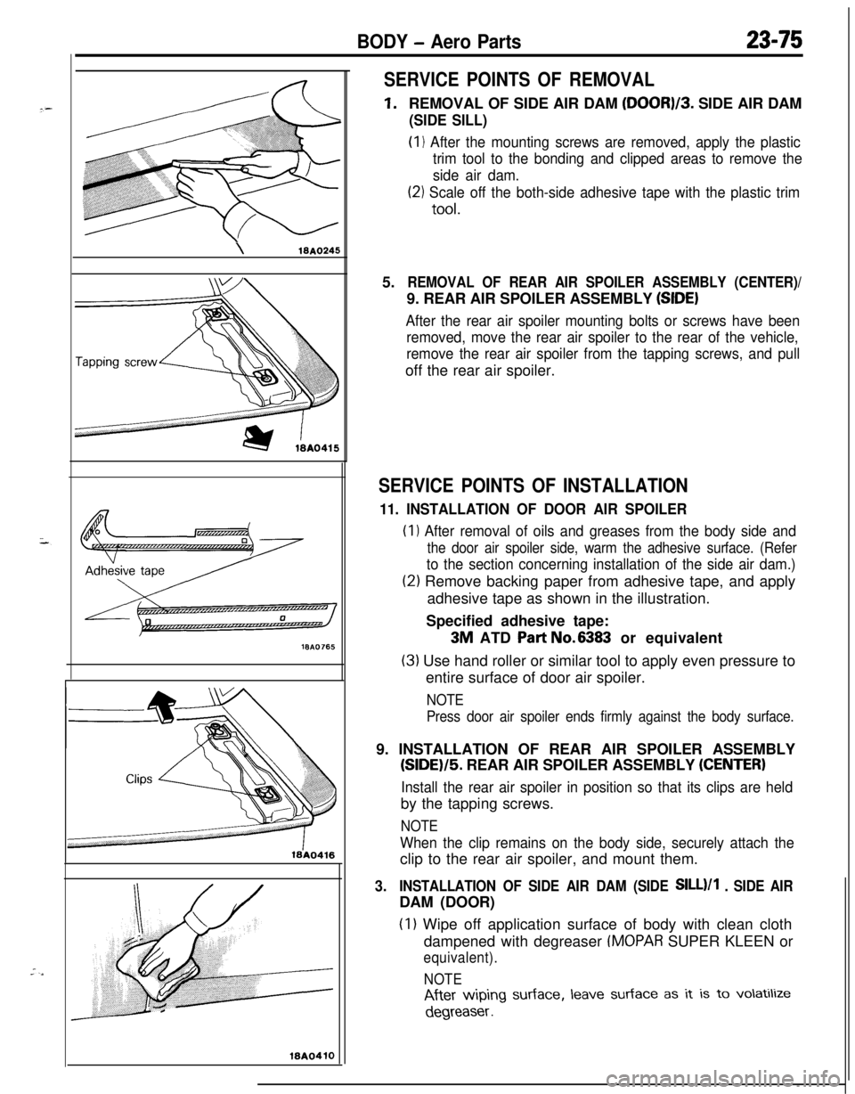
1.REMOVAL OF SIDE AIR DAM (DOOR)/3. SIDE AIR DAM
(SIDE SILL)(I
1 After the mounting screws are removed, apply the plastic
trim tool to the bonding and clipped areas to remove the
side air dam.
(21 Scale off the both-side adhesive tape with the plastic trim
tool.5.
REMOVAL OF REAR AIR SPOILER ASSEMBLY (CENTER)/9. REAR AIR SPOILER ASSEMBLY
(SIDE)
After the rear air spoiler mounting bolts or screws have been
removed, move the rear air spoiler to the rear of the vehicle,
remove the rear air spoiler from the tapping screws, and pulloff the rear air spoiler.
SERVICE POINTS OF INSTALLATION
11. INSTALLATION OF DOOR AIR SPOILER(I
1 After removal of oils and greases from the body side and
the door air spoiler side, warm the adhesive surface. (Refer
to the section concerning installation of the side air dam.)
(2) Remove backing paper from adhesive tape, and apply
adhesive tape as shown in the illustration.
Specified adhesive tape:
3M ATD Part No.6383 or equivalent
(3) Use hand roller or similar tool to apply even pressure to
entire surface of door air spoiler.
NOTE
Press door air spoiler ends firmly against the body surface.9. INSTALLATION OF REAR AIR SPOILER ASSEMBLY
(SIDE)/5. REAR AIR SPOILER ASSEMBLY (CENTER)
Install the rear air spoiler in position so that its clips are heldby the tapping screws.
NOTE
When the clip remains on the body side, securely attach theclip to the rear air spoiler, and mount them.
3.INSTALLATION OF SIDE AIR DAM (SIDE SILL)/1 . SIDE AIRDAM (DOOR)
(I 1 Wipe off application surface of body with clean cloth
dampened with degreaser
IMOPAR SUPER KLEEN or
equivalent).
NOTE
After wiping surface, leave surface as it is to volatilize
degreaser .
Page 1120 of 1216
23-76BODY - Aero Parts
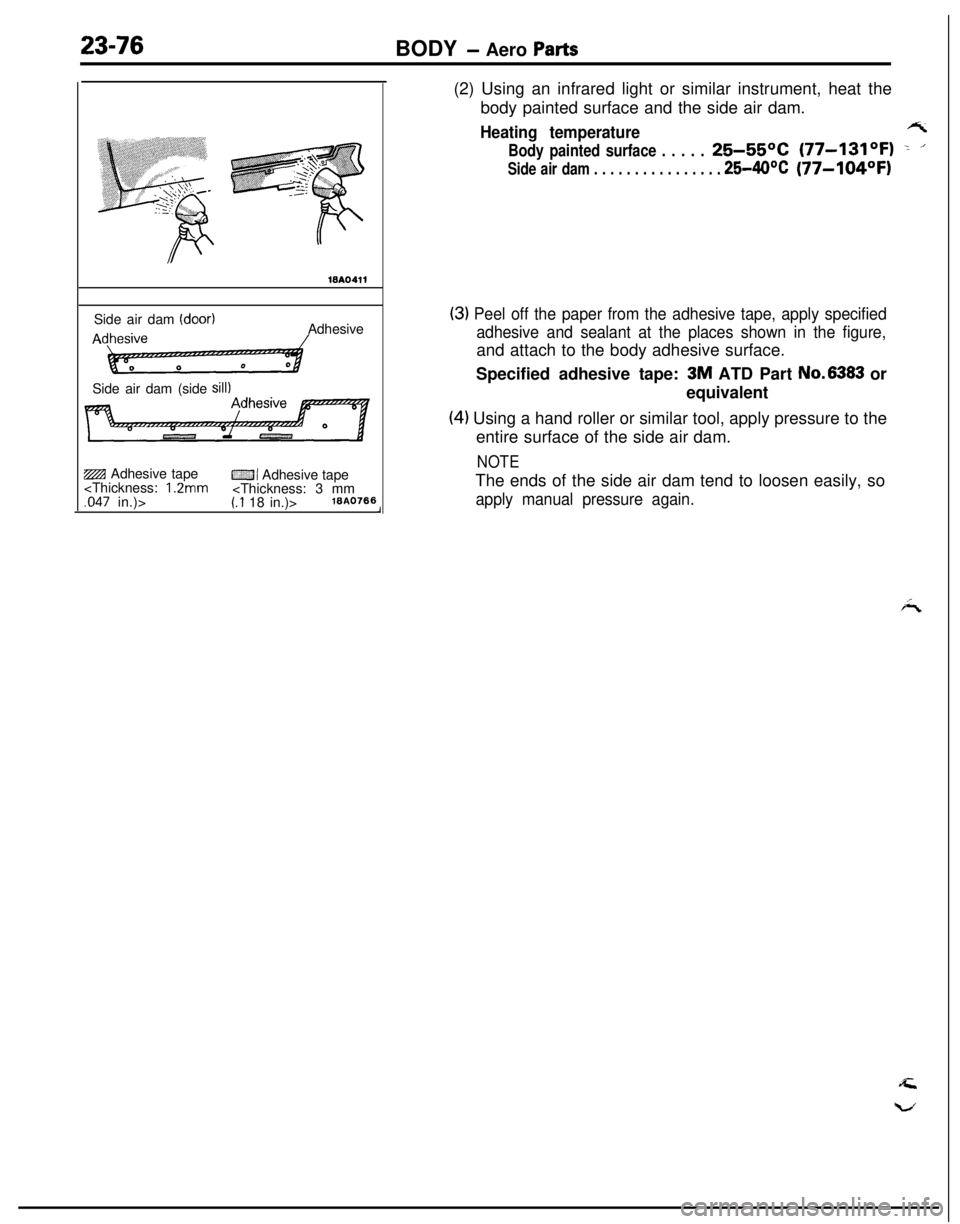
WA0411Side air dam
(door)AAdhesive
Side air dam (side
sill)ZBI Adhesive tape
CZJI Adhesive tape
body painted surface and the side air dam.
Heating temperaturert
Body painted surface . . . . .25-55OC (77-131OF) -. ’
Side air dam . . . . . . . . . . . . . . . . 25-40°C(77-104OFI
(3) Peel off the paper from the adhesive tape, apply specified
adhesive and sealant at the places shown in the figure,and attach to the body adhesive surface.
Specified adhesive tape:
3M ATD Part No.6383 or
equivalent
(4) Using a hand roller or similar tool, apply pressure to the
entire surface of the side air dam.
NOTEThe ends of the side air dam tend to loosen easily, so
apply manual pressure again.