MITSUBISHI ECLIPSE 1991 Service Manual
Manufacturer: MITSUBISHI, Model Year: 1991, Model line: ECLIPSE, Model: MITSUBISHI ECLIPSE 1991Pages: 1216, PDF Size: 67.42 MB
Page 431 of 1216
INTAKE AND EXHAUST - Air Cleaner
REMOVAL AND INSTALLATION
<2.0L DOHC Engine (Turbo)>
II-S
8-10 Nm6-7, ft.lbs.12-15 Nm9- 11 ftlbs.
/
8
18
05AO167
605A0182
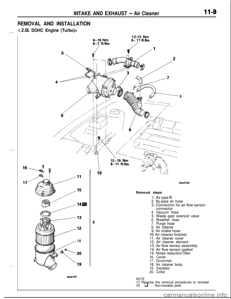
Removal steps
1. Air pipe
B2. By-pass air hose3. Connection for air flow sensor
connector
4.Vacuum hose
5. Waste gate solenoid valve
6.Breather hose7.Purge hose8.Air cleaner9. Air intake hose
10. Air cleaner bracket11. Air cleaner cover
12. Air cleaner element13. Air flow sensor assembly
14. Air flow sensor gasket
15. Noise reduction filter
16.Cover17.Grommet
18. Air cleaner body
19.Insulator20.Collar
NOTE(1) Reverse the removal procedures to reinstall.(2) q : Non-reusable parts
Page 432 of 1216
INTAKE AND EXHAUST - Air Cleaner
< Non-Turbo >
Air flow sensorside connector
6FUO622
c Turbo >
6FUO623
INSPECTIONNllFCAB0
Check the air cleaner body, cover or packing for ~
deformation, corrosion or damage.%al
Check the air duct for damage.d0
Check the air cleaner element for clogging, contamination or
damage.
If element is slightly clogged, remove dust by blowing air
from inside of element.
AIR-FLOW SENSOR CHECK
For inspection of air-flow sensor, refer to GROUP 14-Air-Flow
Sensor Check.
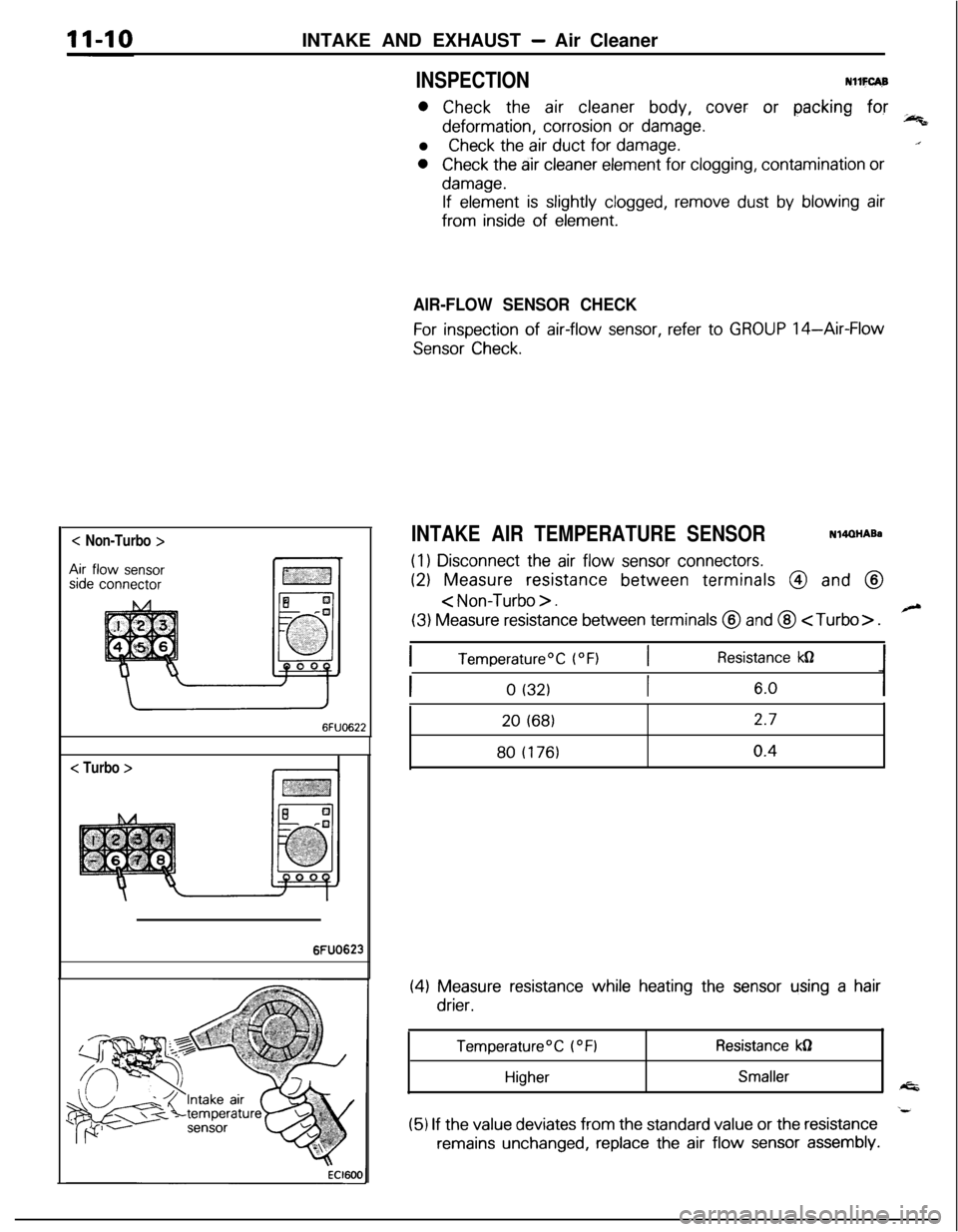
INTAKE AIR TEMPERATURE SENSORN14QHABa
(1) Disconnect the air flow sensor connectors.
(2) Measure resistance between terminals @ and @
< Non-Turbo > .
(3) Measure resistance between terminals @ and @
ITemperature”C (“F)IResistance kn
0 (32)6.020
(68)2.780
(176)0.4
(4) Measure resistance while heating the sensor using a hair
drier.
Temperature’C (OFIResistance kdl
HigherSmaller
(5) If the value deviates from the standard value or the resistance
remains unchanged, replace the air flow sensor assembly.
Page 433 of 1216

INTAKE AND EXHAUST - Intercooler11-11
INTERCOOLER
A-- REMOVAL AND INSTALLATIONNllTA-.
615-22
Nm11-16 ft.lbs.
Removal steps
1. Air hose C
2. Air pipe B3. Air by-pass hose4.Vacuumhose
5.Vacuumhose
l *6. Air cleaner7. Air intake hose8. Air hose B
9. Splash shield extensionl + 10. Intercooler11. Air hose A12. Air by-pass valve13.Gasket
i
05AOl85
05A0140
NOTE(1) Reverse the removal procedures to reinstall.(2) l * : Refer to “Service Points of Removal”.(3) *+ : Refer to “Service Points of Installation”(4) q : Non-reusable parts
Page 434 of 1216

11-12INTAKE AND EXHAUST - Intercooler
05AO184
SERVICE POINTS OF REMOVAL6. REMOVAL OF AIR CLEANER
Refer to P.l l-9.
INSPECTIONNllTCAA
l
Check the intercooler fins for bending, damage, or foreign
matter.0
Check the intercooler hoses for cracking, damage, or wear.
SERVICE POINTS OF INSTALLATIONNllTDAB
10. INSTALLATION OF
INTERCObLER
Connect the air hoses and air pipes by aligning the paint
marks on the hoses with the projections and indentations on?
the pipes.
Caution
Be careful not to allow any foreign matter to get into thehoses, pipes, or the
intercooler itself.
NOTE
@ : Projection or indentation (pipe)
+ : Paint mark (hose)
Page 435 of 1216
INTAKE AND EXHAUST - Intake Manifold < 1.8L Engine>
INTAKE MANIFOLD < 1.8L Engine>
.- REMOVAL AND INSTALLATION
11-13NllMA-A.-
. .
4-6 Nmpy---- 3-4 ft.lbs.
B05A0132
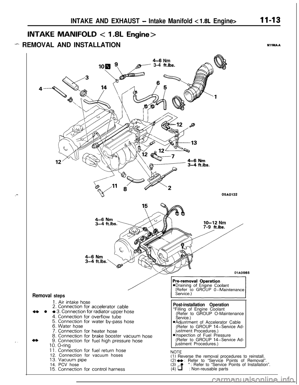
Removal steps
1. Air intake hose2. Connection for accelerator cable
4, l + 3. Connection for radiator upper hose
4. Connection for overflow tube5. Connection for water by-pass hose6. Water hose
7. Connection for heater hose8. Connection for brake booster vacuum hose9. Connection for fuel high pressure hose10. O-ring
11. Connection for fuel return hose12. Connection for vacuum hoses
13. Vacuum pipe14. PCV hose
15. Connection for control harness
IO-12 Nm7-9 ft.lbs.
OlA0565
Post-installation Operation
NfJTF*Filling of Engine Coolant
(Refer to GROUP O-Maintenance
Service.)aAdjustment of Accelerator Cable
(Refer to GROUP 14-Service Ad-
justment Procedures.)*Inspection of Fuel Pressure
(Refer to GROUP 14-Service Ad-
justment Procedures.)
I.” IL(1) Reverse the removal procedures to reinstall.(2) +* : Refer to “Service Points of Removal”.(3) l * : Refer to “Service Points of Installation”.
(4) q : Non-reusable parts
Page 436 of 1216
II-14INTAKE AND EXHAUST -Intake Manifold < 1.8L Engine>
/15-20 Nm
11-14
ft.lbs.
lo-13 Nm
18167-9 ft.lbs.15-20 Nm11-14
ft.lbs.I/15-20 Nm
I26IO-15 Nm7-11
ftm’bs.
-17-20 Nm
12-14 ft.lbs.15-20 Nm
Removal steps05AO180
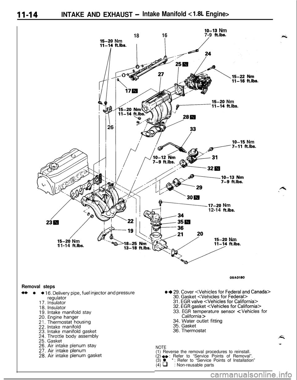
+* l a 16. Delivery pipe, fuel injector and pressureregulator17.Insulator
18.Insulator19. Intake manifold stay20.Engine hanger
2 1.Thermostat housing22.Intake manifold23. Intake manifold gasket24. Throttle body assembly25.Gasket26. Air intake plenum stay
27. Air intake plenum
28. Air intake plenum gasket
lb+ 29. Cover
33. EGR temperature sensor
NOTE(1) Reverse the removal procedures to reinstall.
(2) a* : Refer to “Service Points of Removal”.
(3) l * : Refer to “Service Points of Installation”
(4) q : Non-reusable parts
Page 437 of 1216
INTAKE AND EXHAUST - Intake Manifold < 1.8L Engine>1145
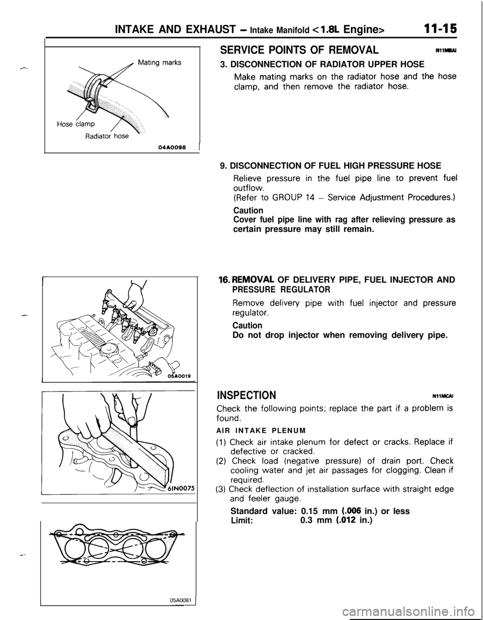
SERVICE POINTS OF REMOVALNllMBAI
3. DISCONNECTION OF RADIATOR UPPER HOSE
Make mating marks on the radiator hose and the hose
clamp, and then remove the radiator hose.
r
04A0088 19. DISCONNECTION OF FUEL HIGH PRESSURE HOSE
Relieve pressure in the fuel pipe line to prevent fueloutflow.
(Refer to GROUP 14 - Service Adjustment Procedures.)
Caution
Cover fuel pipe line with rag after relieving pressure ascertain pressure may still remain.16.REMOVAL OF DELIVERY PIPE, FUEL INJECTOR AND
PRESSURE REGULATOR
Remove delivery pipe with fuel injector and pressure
regulator.
CautionDo not drop injector when removing delivery pipe.
INSPECTIONNllMCAl
Check the following points; replace the part if a problem isfound.
AIR INTAKE PLENUM
(1) Check air intake plenum for defect or cracks. Replace ifdefective
or cracked.
(2) Check load (negative pressure) of drain port. Check
cooling water and jet air passages for clogging. Clean if
required.
(3) Check deflection of installation surface with straight edge
and feeler gauge.Standard value: 0.15 mm
(.006 in.) or less
Limit:0.3 mm (.012 in.)05AOOB4
Page 438 of 1216
II-16INTAKE AND EXHAUST - Intake Manifold c 1.8L Engine>
05A0033
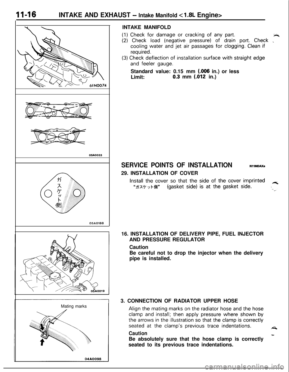
0580188Mating marksINTAKE MANIFOLD
(1) Check for damage or cracking of any part.+4
(2) Check load (negative pressure) of drain port. Check ,cooling water
and jet air passages for clogging. Clean if
required.
(3) Check deflection of installation surface with straight edge
and feeler gauge.Standard value: 0.15 mm
(006 in.) or less
Limit:
0.3 mm (.012 in.)
SERVICE POINTS OF INSTALLATIONNllMDAXa
29. INSTALLATION OF COVER
Install the cover so that the side of the cover imprinted
“fj‘x? ‘Y bf4l~(gasket side) is at the gasket side.-T16. INSTALLATION OF DELIVERY PIPE, FUEL INJECTOR
AND PRESSURE REGULATOR
Caution
Be careful not to drop the injector when the delivery
pipe is installed.
3. CONNECTION OF RADIATOR UPPER HOSEAlign the
mating marks on the radiator hose and the hose
clamp and install; then apply pressure where shown bythe
arrows in the illustration so that the clamp is correctly
seated at the clamp’s previous trace indentations.A
Caution
-Be absolutely sure that the hose clamp is correctly
seated to its previous trace indentations.
Page 439 of 1216
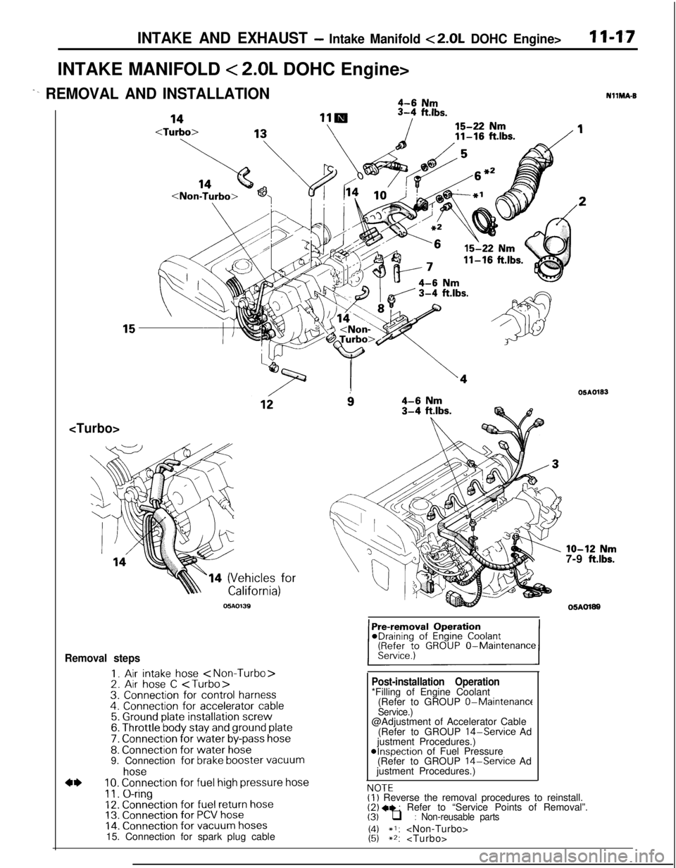
INTAKE AND EXHAUST - Intake Manifold <2.0L DOHC Engine>I I-1.7INTAKE MANIFOLD
< 2.0L DOHC Engine>
^- REMOVAL AND INSTALLATION4-6 Nm
ft.lbs.
14 (Vehicles for
05AO139
i34-6 Nm3-4 ftlbs.
Removal steps
I. Air intake hose
7. Connection for water by-pass hose8. Connection for water hose9. Connection for brake booster vacuum
4*
hose10. Connection for fuel high pressure hose
11. O-ring12. Connection for fuel return hose13. Connection for PCV hose14. Connection for vacuum hoses15. Connection for spark plug cable
Post-installation Operation*Filling of Engine Coolant
(Refer to GROUP 0-Maintenance
Service.)@Adjustment of Accelerator Cable
(Refer to GROUP
14-Service Ad
justment Procedures.)
@Inspection of Fuel Pressure
(Refer to GROUP 14-Service Ad
justment Procedures.)
NOTFNllMA-B
OSAO133
lo-12 Nm7-9 ft.lbs.
05AOl89
,.-.-(I) Reverse the removal procedures to reinstall.(2) +e : Refer to “Service Points of Removal”.(3) q : Non-reusable parts
1:;*I:
Page 440 of 1216
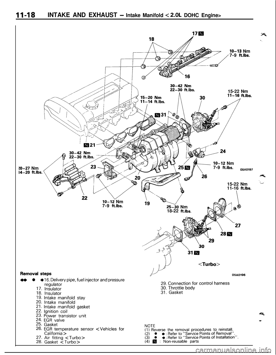
11-18INTAKE AND EXHAUST - Intake Manifold < 2.0L DOHC Engine>
10-27 Nm14-20 ft.lbs.
18hIO-13 Nm
7-9
ft.lbs.15-22 Nm11-16
ft.lbs.IO-12 Nm
7-9
ftlbs.05A0197
15-22 Nm
11-16
ftlbs.
wi2” vlo-12 Nm
7-9 ftlbs.25-30 Nm
18-22
ft.lbs.
24
\‘27
28lll
Removal steps
+e l + 16. Delivery pipe, fuel injector and pressureregulator17. Insulator18. Insulator19. Intake manifold stay
20. Intake manifold21. Intake manifold gasket22. Ignition coil23. Power transistor unit24. EGR valve25. Gasket26. EGR temperature sensor
29. Connection for control harness
30. Throttle body31. Gasket
NOTE(I) Reverse the removal procedures to reinstall.(2) l * : Refer to “Service Points of Removal”.(3) l + : Refer to “Service Points of Installation”.(4) 0 : Non-reusable parts