MITSUBISHI ECLIPSE 1991 Service Manual
Manufacturer: MITSUBISHI, Model Year: 1991, Model line: ECLIPSE, Model: MITSUBISHI ECLIPSE 1991Pages: 1216, PDF Size: 67.42 MB
Page 441 of 1216
INTAKE AND EXHAUST - Intake Manifold <2.0L DOHC Engine>11-19
SERVICE POINTS OF REMOVALNllMBAJ
10. DISCONNECTION OF FUEL HIGH PRESSURE HOSE
Relieve pressure in the fuel pipe line to prevent fueloutflow.
(Refer to GROUP 14 - Service Adjustment
Procedures)
CautionCover fuel pipe line with rag after relieving pressure as
certain pressure may still remain.
05AOO28
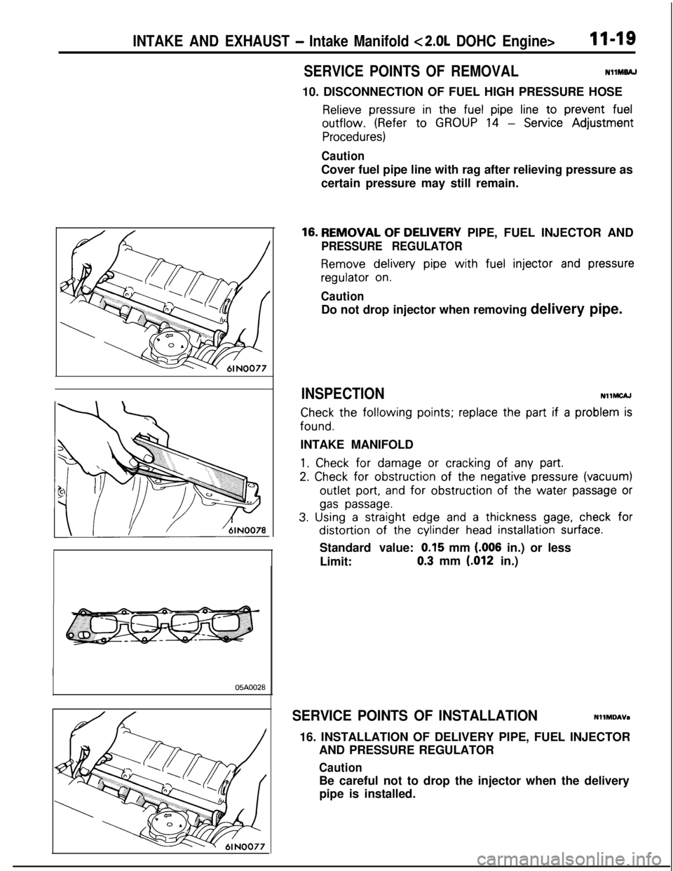
16. REMOVAL OF DELIVERY PIPE, FUEL INJECTOR AND
PRESSURE REGULATOR
Remove delivery pipe with fuel injector and pressureregulator
on.
CautionDo not drop injector when removing delivery pipe.
INSPECTIONNllMCAJ
Check the following points; replace the part if a problem isfound.
INTAKE MANIFOLD
1. Check for damage or cracking of any part.
2. Check for obstruction of the negative pressure (vacuum)outlet
port, and for obstruction of the water passage or
gas passage.
3. Using a straight edge and a thickness gage, check fordistortion of the cylinder
head installation surface.Standard value:
0.15 mm (.006 in.) or less
Limit:0.3 mm
(012 in.)
SERVICE POINTS OF INSTALLATIONNllMDAVa
16. INSTALLATION OF DELIVERY PIPE, FUEL INJECTOR
AND PRESSURE REGULATOR
CautionBe careful not to drop the injector when the delivery
pipe is installed.
Page 442 of 1216
II-20INTAKE AND EXHAUST - Turbocharger
TURBOCHARGER
REMOVAL AND INSTALLATION
II
NHLA-
Pre-removal Operation*Draining Engine Coolant
(Refer to GROUP
0-Maintenance Service.)
*Draining Engine Oil
(Refer to GROUP g-Engine
Adjustment.)1
Po+installation Operationl Flllrng Engine Oil(Refer to GROUP O-Main@
nance Service.)l Filling Engine Coolant(Refer to GROUP O-Mainte-
nance Service.)
12-15 Nm12-15 Nm
9- 11ft.lbs.3
12-15 Nm
9-l 1 ftlbs
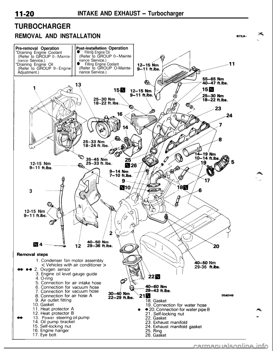
moval steps
1. Condenser fan motor assembly< Vehicles with air conditioner >) *4 2. Oxygen sensor3. Engine oil level gauge guide4. O-ring
5. Connection for air intake hose6. Connection for vacuum hose7. Connection for vacuum hose8. Connection for air hose A9. Air outlet fitting
10.Gasket1 1.Heat protector A12. Heat protector B13. Power steering oil pump14. Oil pump bracket15.Self-locking nut16.Engine hanger17.Eye bolt
h-50 Nm29-36 ft.lbs.
19. Connection for water hosel * 20. Connection for water pipe f321. Self-locking nut22. Gasket23. Exhaust manifold24. Exhaust manifold gasket25. Ring26. Gasket
05M1149
Page 443 of 1216

INTAKE AND EXHAUST - Turbocharger11-21
35-50 Nm25-Qg
ft-lbs*26-34 Nm
20-25 ftlbs.
\/3655-65 Nm
4o-4: ft*lbs-
35-50 Nm25-36 ftlbs.
05A0136
NOTE(1) Reverse the removal procedures to reinstall.(2) l * : Refer to “Service Points of Removal”.(3) l + : Refer to “Service Points of Installation”.(4) q : Non-reusable parts
27. Oil return pipe28.
Gasketl * l a 29. Turbocharger30. Eye bolt
31. Gasket
32. Water pipe B33. Eye bolt
34. Gasket35. Water pipe A36. Eye bolt37. Gasketw l c 38. Oil pipe39. Exhaust fitting40. GasketMD998748
1SERVICE POINTS OF REMOVALNllL9AD
2. REMOVAL OF OXYGEN SENSORDisconnect the
connector of the oxygen sensor, and install
the special tool to the oxygen sensor.
Then, using an offset (box-end) wrench, remove the oxygen
sensor.
Page 444 of 1216
INTeKE AND EXHAUST - Turbocharger
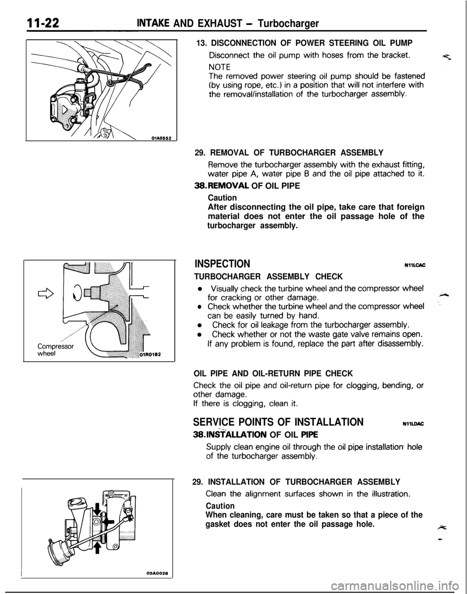
13. DISCONNECTION OF POWER STEERING OIL PUMP
Disconnect the oil pump with hoses from the bracket.
NOTE
The removed power steering oil pump should be fastened
(by using rope, etc.) in a position that will not interfere with
the removal/installation of the turbocharger assembly.
I05AOO26
29. REMOVAL OF TURBOCHARGER ASSEMBLY
Remove the turbocharger assembly with the exhaust fitting,water
pipe A, water pipe 6 and the oil pipe attached to it.3B.REMOVAL OF OIL PIPE
CautionAfter disconnecting the oil pipe, take care that foreign
material does not enter the oil passage hole of the
turbocharger assembly.
INSPECTIONNllLCAC
TURBOCHARGER ASSEMBLY CHECKl
Visually check the turbine wheel and the compressor wheelfor
cracking or other damage.
lCheck whether the turbine wheel and the compressor wheel
can be easily turned by hand.l
Check for oil leakage from the turbocharger assembly.l
Check whether or not the waste gate valve remains open.
If any problem is found, replace the part after disassembly.
OIL PIPE AND OIL-RETURN PIPE CHECK
Check the oil pipe and oil-return pipe for clogging, bending, or
other damage.
If there is clogging, clean it.
SERVICE POINTS OF INSTALLATIONNllLDAC-x_3SlNSTALLATlON OF OIL PlPE
Supply clean engine oil through the oil pipe installation hole
of the turbocharger assembly.
29. INSTALLATION OF TURBOCHARGER ASSEMBLY
Clean the alignment surfaces shown in the illustration.
Caution
When cleaning, care must be taken so that a piece of the
gasket does not enter the oil passage hole.
Page 445 of 1216

INTAKE AND EXHAUST - TurbochargerII-23
05K557
’ MD998748
05A0023
DISASSEMBLY AND REASSEMBLY20.lNSTALLATlON OF WATER PIPE
(B)
Before installing to the water inlet pipe, apply machine oil to
the inner surface of the pipe flare.2. INSTALLATION OF OXYGEN SENSOR
Use the special tool to install the oxygen sensor.NllLE-.
lo-13 Nm7-9 Mbs.
Disassembly steps
1. Snap pin2. Waste gate actuator
3. Couplingl 4. Turbine housingl *l C 5. Snap ring+e *a 6. Cartridge assemblyl * 7. O-ring8. Compressor cover
NOTE(I) Reverse the disassembly procedures to reassemble.(2) 4~ : Refer to “Service Points of Disassembly”.
(3) ++ : Refer to “Service Points of Reassembly”.
(4) q : Non-reusable parts6 1 NO084
Page 446 of 1216
II-24INTAKE AND EXHAUST - TurbochargerSERVICE POINTS OF DISASSEMBLYNllLFAB
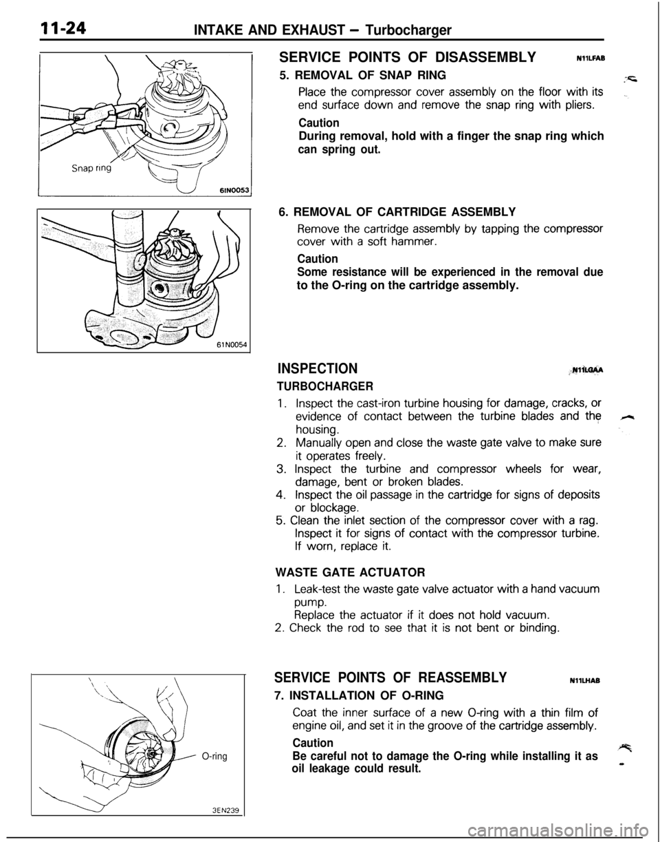
5. REMOVAL OF SNAP RING
Place the compressor cover assembly on the floor with its
end surface down and remove the snap ring with pliers.
CautionDuring removal, hold with a finger the snap ring which
can spring out.
O-ring
3EN2396. REMOVAL OF CARTRIDGE ASSEMBLY
Remove the cartridge assembly by tapping the compressor
cover with a soft hammer.
Caution
Some resistance will be experienced in the removal dueto the O-ring on the cartridge assembly.
INSPECTION;.rulim+A
TURBOCHARGER
1.Inspect the cast-iron turbine housing for damage, cracks, or
evidence of contact between the turbine blades and the
housing.
2.Manually open and close the waste gate valve to make sure
it operates freely.
3. Inspect the turbine and compressor wheels for wear,
damage, bent or broken blades.
4.Inspect the oil passage in the cartridge for signs of deposits
or blockage.
5. Clean the inlet section of the compressor cover with a rag.
Inspect it for signs of contact with the compressor turbine.
If worn, replace it.WASTE GATE ACTUATOR
1.Leak-test the waste gate valve actuator with a hand vacuum
pump.Replace the actuator if it does not hold vacuum.
2. Check the rod to see that it is not bent or binding.
SERVICE POINTS OF REASSEMBLYNllLHAB
7. INSTALLATION OF O-RING
Coat the inner surface of a new O-ring with a thin film of
engine oil, and set it in the groove of the cartridge assembly.
Caution
Be careful not to damage the O-ring while installing it as
oil leakage could result.
Page 447 of 1216
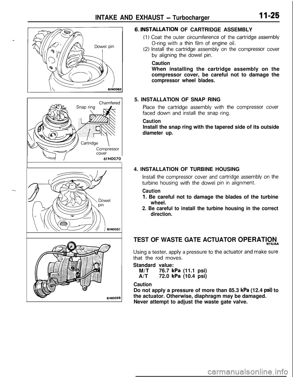
INTAKE AND EXHAUST - Turbocharger~1xz5
--=+I61 NO0706lN005E6.
INSTALLATIQN OF CARTRIDGE ASSEMBLY
(I1 Coat the outer circumference of the cartridge assembly
O-ring with a thin film of engine oil.
(29 Install the cartridge assembly on the compressor cover
by aligning the dowel pin.
CautionWhen installing the cartridge assembly on the
compressor cover, be careful not to damage the
compressor wheel blades.5. INSTALLATION OF SNAP RING
Place the cartridge assembly with the compressor cover
faced down and install the snap ring.
CautionInstall the snap ring with the tapered side of its outside
diameter up.4. INSTALLATION OF TURBINE HOUSING
Install the compressor cover and cartridge assembly on the
turbine housing with the dowel pin in alignment.
Caution
1. Be careful not to damage the blades of the turbine
wheel.
2. Be careful to install the turbine housing in the correct
direction.
TEST OF WASTE GATE ACTUATOR OPERATIONNllLlAA
Using a tester, apply a pressure to the actuator and make surethat the
rod moves.Standard value:
M/T76.7
kPa (11.1 psi)
A/T72.0
kPa (10.4 psi)
CautionDo not apply a pressure of more than 85.3
kPa (12.4 psi) to
the actuator. Otherwise, diaphragm may be damaged.
Never attempt to adjust the waste gate valve.
Page 448 of 1216
1 I-26INTAKE AND EXHAUST -Exhaust Manifold c 1.8L Engine>
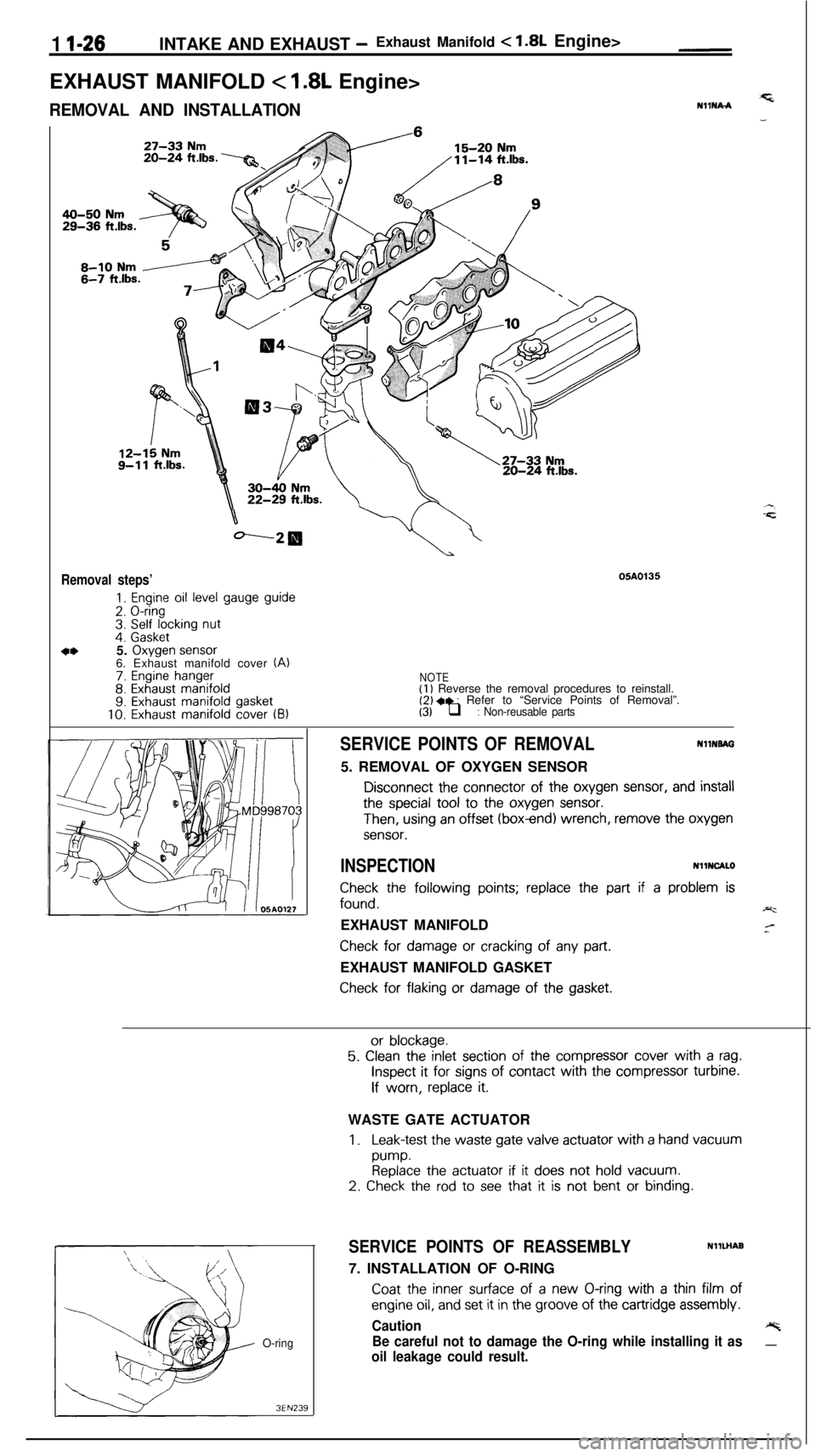
EXHAUST MANIFOLD
< 1.8L Engine>
REMOVAL AND INSTALLATION
20-24 ft.lbs.
05A0135Removal steps’
1. Engine oil level gauge guide
2. O-ring3. Self locking nut4. Gasket5. Oxygen sensor6. Exhaust manifold cover (A)
7. Engine hanger8. Exhaust manifold9. Exhaust manifold gasket10. Exhaust manifold cover (B)
NOTE(1) Reverse the removal procedures to reinstall.(2) 4, : Refer to “Service Points of Removal”.(3) q : Non-reusable parts
SERVICE POINTS OF REMOVALNHNBAG5. REMOVAL OF OXYGEN SENSOR
Disconnect the connector of the oxygen sensor, and install
the special tool to the oxygen sensor.
Then, using an offset (box-end) wrench, remove the oxygen
sensor.
INSPECTIONNllNCALO
Check the following points; replace the part if a problem is
found.-y=.EXHAUST MANIFOLD
Check for damage or cracking of any part.EXHAUST MANIFOLD GASKET
Check for flaking or damage of the gasket.
O-ring
3EN239
or blockage.
5. Clean the inlet section of the compressor cover with a rag.
Inspect it for signs of contact with the compressor turbine.
If worn, replace it.WASTE GATE ACTUATOR
1.Leak-test the waste gate valve actuator with a hand vacuum
pump.
Replace the actuator if it does not hold vacuum.
2. Check the rod to see that it is not bent or binding.
SERVICE POINTS OF REASSEMBLYNllLHAB
7. INSTALLATION OF O-RING
Coat the inner surface of a new O-ring with a thin film of
engine oil, and set it in the groove of the cartridge assembly.
Caution+%
Be careful not to damage the O-ring while installing it as__
oil leakage could result.
Page 449 of 1216
INTAKE AND EXHAUST- Exhaust Manifold <2.0L DOHC Engine (Non-Turbo) >11-27
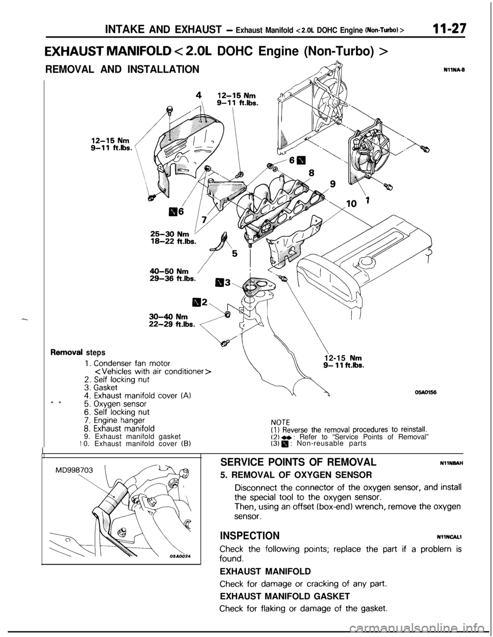
EXHAUST MANIFOLD < 2.0L DOHC Engine (Non-Turbo) >
REMOVAL AND INSTALLATION,lcIii3\
I-**1
steps
1.Condenserfanmotor
2. Self locking nut3.Gasket
4. Exhaust manifold cover (A)12-15
Nm9- 11 ft.lbs.
06AOl56
5. Oxygen sensor6. Self locking nut
7. Engine hanger
8. Exhaust manifold9. Exhaust manifold gasket
0. Exhaust manifold cover
(B)
NOTE(I) Reverse the removal procedures to reinstall.(2) +* : Refer to “Service Points of Removal”(3) 0 : Non-reusable parts
NllNA6
SERVICE POINTS OF REMOVALNllNSAH
5. REMOVAL OF OXYGEN SENSOR
Disconnect the connector of the oxygen sensor, and installthe special tool
to the oxygen sensor.
Then, using an offset (box-end) wrench, remove the oxygen
sensor.
INSPECTIONNllNCALl
Check the following points; replace the part if a problem is
found.EXHAUST MANIFOLD
Check for damage or cracking of any part.EXHAUST MANIFOLD GASKET
Check for flaking or damage of the gasket.
Page 450 of 1216
11-28INTAKE AND EXHAUST - Exhaust Manifold ~2.0~ DOHC Enoine (Turbo)>
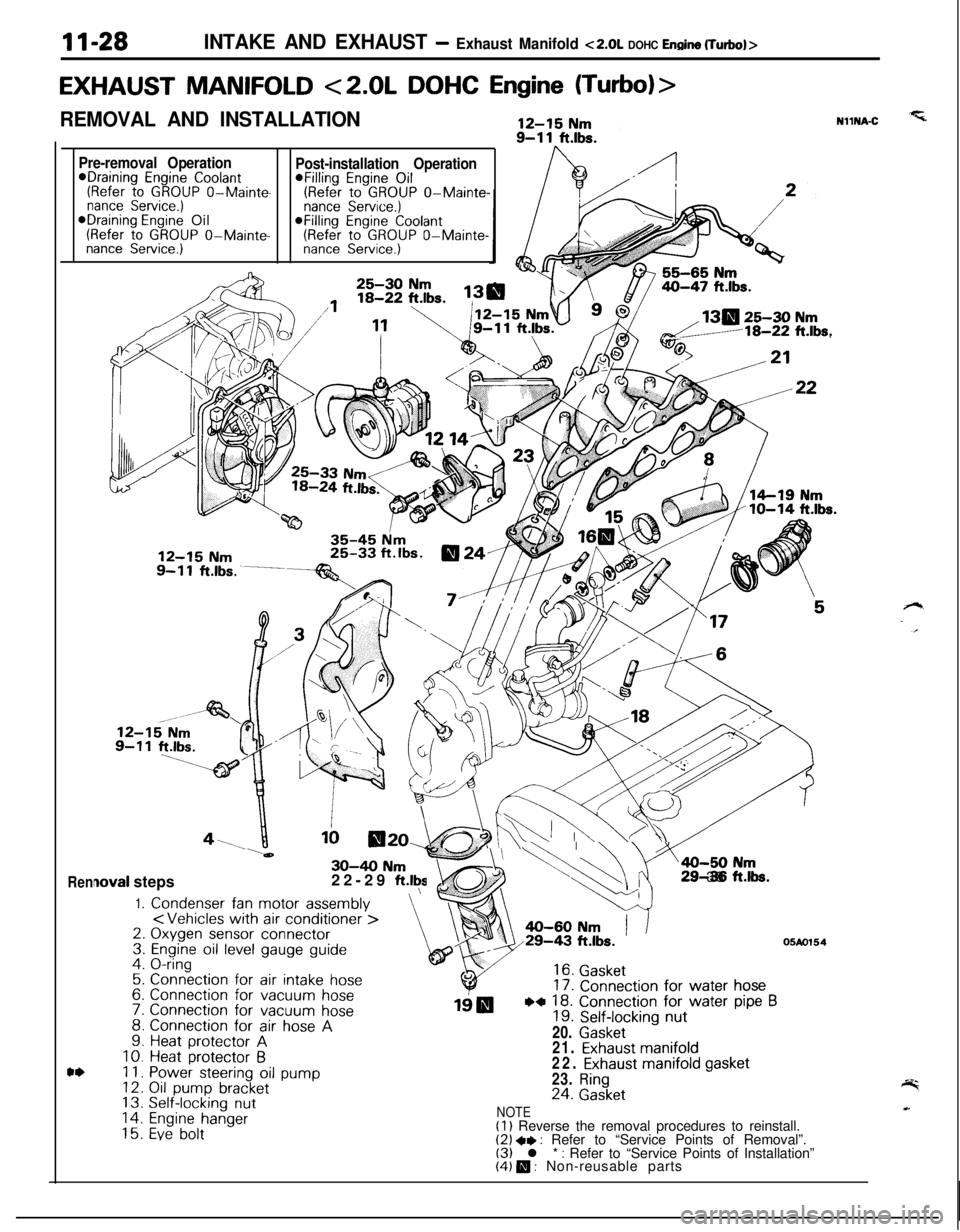
EXHAUST MANIFOLD <2.0L DOHC Engine (Turbo)>
REMOVAL AND INSTALLATION
Pre-removal Operation*Draining Engine Coolant(Refer to GROUP O-Mainte-nance Service.)*Draining Engine Oil(Refer to GROUP O-Mainte-nance Service.)
Rennova1 steps
1.Condenser fan motor assembly
\30-40 Nm22-29 ft.lty3. & (
EJ\\=a-50 N
4 .ri29-38 ftk.
,
Post-installation Operation@Filling Engine Oil(Refer to GROUP O-Mainte-nance Service.)@Filling Engine Coolant(Refer to GROUP O-Mainte-nance Service.)NllNA-C
130 25-30 Nmd/18-22 ft.lbs.
;:4.
s5:7.
::10.Ii.12.13.14.15.
Connection for air intake hose
Connection for vacuum hoseConnection for vacuum hoseConnection for air hose AHeat protector AHeat protector 6Power steering oil pumpOil pump bracketSelf-locking nut
Engine hangerEve bolt
16. Gasket17. Connection for water hose
19IBWI 18. Connection for water pipe B19. Self-locking nut20.
Gasket
05Ao15421.
Exhaust manifold22. Exhaust manifold gasket23.
Ring24. Gasket
NOTE(1) Reverse the removal procedures to reinstall.(2) +, : Refer to “Service Points of Removal”.(3) l * : Refer to “Service Points of Installation”(4) m : Non-reusable parts