MITSUBISHI ECLIPSE 1991 Service Manual
Manufacturer: MITSUBISHI, Model Year: 1991, Model line: ECLIPSE, Model: MITSUBISHI ECLIPSE 1991Pages: 1216, PDF Size: 67.42 MB
Page 531 of 1216
FUEL SYSTEM - MPI Svstem InsDection <2.0L DOHC Engine>14-77INSTALLATION
(1) Apply specified sealant to threaded portion and tighten to
specified torque.
Specified sealant: MOPAR Part No.4318034 or
equivalent
Specified torque: 20
- 40 Nm (15 - 29 ft.lbs.1(2) Fasten harness connectors securely.
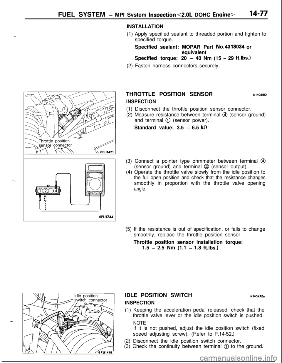
THROTTLE POSITION SENSOR
INSPECTION
N14QBBKl(1) Disconnect the throttle position sensor connector.
(2) Measure resistance between terminal
@I (sensor ground)
and terminal
@ (sensor power).
Standard value: 3.5
- 6.5 kR(3) Connect a pointer type ohmmeter between terminal
@I(sensor ground) and terminal
@ (sensor output).
(4) Operate the throttle valve slowly from the idle position to
the full open position and check that the resistance changessmoothly in proportion with the throttle valve opening
angle.
6FU1244(5) If the resistance is out of specification, or fails to change
smoothly, replace the throttle position sensor.
Throttle position sensor installation torque:
1.5
- 2.5 Nm (1.1 - 1.8 ft.lbs.)
J II\/ hFU1419IDLE POSITION SWITCH
INSPECTION
N14QKAEa(1) Keeping the acceleration pedal released, check that the
throttle valve lever or the idle position switch is pushed.
NOTEIf it is not pushed, adjust the idle position switch (fixed
speed adjusting screw). (Refer to
P.14-52.)(2) Disconnect the idle position switch connector.
(3) Check the continuity between terminal
@) to the ground.
Page 532 of 1216
FUEL SYSTEM - MPI System Inspection <2.0L DOHC Engine>
6FUO999
Accelerator pedal
DepressedContinuity .
Non-conductive
(03 fl)
ReleasedIConductive (0 fl)I(4) Replace the idle position switch if faulty.
NOTE
For replacement procedure, refer to the idle position switch(fixed speed adjusting screw) adjustment section
(P.14-
52.).OXYGEN SENSOR
NllQDeJ
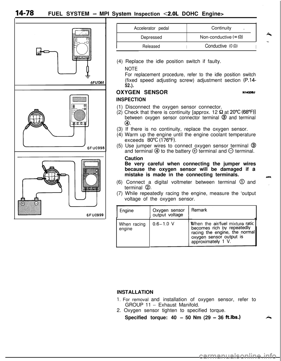
INSPECTION(1) Disconnect the oxygen sensor connector.
(2) Check that there is continuity [approx. 12
52 at 20°C (68”F)l
between oxygen sensor connector terminal @ and terminal
GO.(3) If there is no continuity, replace the oxygen sensor.
(4) Warm up the engine until the engine coolant temperature
exceeds
80°C (176°F).(5) Use jumper wires to connect oxygen sensor terminal
@and terminal
@ to the battery @ terminal and 0 terminal.
Caution
Be very careful when connecting the jumper wires
because the oxygen sensor will be damaged if a
mistake is made in the connecting terminals.
(6) Connect a digital voltmeter between terminal
@ and
terminal
0.(7) While repeatedly racing the engine, measure the ‘output
voltage of the oxygen sensor.
When racing
engineWhen the
air/fuel mixture raticINSTALLATION
1. For removal and installation of oxygen sensor, refer to
GROUP 11
- Exhaust Manifold.
2. Oxygen sensor tighten to specified torque.
Specified torque: 40
- 50 Nm (29 - 36 ft.lbs.)
Page 533 of 1216
FUEL SYSTEM - MPI System Inspection <2.0L QOHC Engine>14-79EGR TEMPERATURE SENSOR
N14RCHAaRefer to GROUP 25
- Exhaust Gas Recirculation System.
VEHICLE SPEED SENSOR
Refer to GROUP 8
- Meters and Gauges.
N140EBBaAIR CONDITIONER SWITCH
Nl4QQAEaRefer to GROUP 8
- Column Switch.
POWER STEERING OIL PRESSURE SWITCH
N14RCJBRefer to GROUP 19 for power steering system inspection.
INJECTORS
NWXAHCHECKING OPERATION SOUND
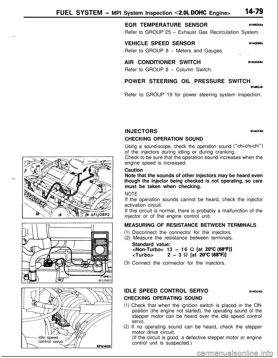
Using a sound-scope, check the operation sound (“chi-chi-chi”)of the injectors during idling or during cranking.
Check to be sure that the operation sound increases when the
engine speed is increased.
Caution
Note that the sounds of other injectors may be heard even
though the injector being checked is not operating, so caremust be taken when checking.
NOTEIf the operation sounds cannot be heard, check the injector
activation circuit.
If this circuit is normal, there is probably a malfunction of the
injector or of the engine control unit.
MEASURING OF RESISTANCE BETWEEN TERMINALS
(1) Disconnect the connector for the injectors.
(2) Measure the resistance between terminals.
Standard value:
-16 S2 [at 20°C (68”F)]
- 3 52 [at 20% (68”F)]
(3) Connect the connector for the injectors.
IDLE SPEED CONTROL SERVO
N14QUADCHECKING OPERATING SOUND
(1) Check that when the ignition switch is placed in the ON
position (the engine not started), the operating sound of thestepper motor can be heard over the idle speed control
servo.
(2) If no operating sound can be heard, check the stepper
motor drive circuit.
(If the circuit is good, a defective stepper motor or engine
control unit is suspected.)
Page 534 of 1216
14-80FUEL SYSTEM - MPI System Inspection <2.0L DOHC Enginh
7FUOOlO6FU1426
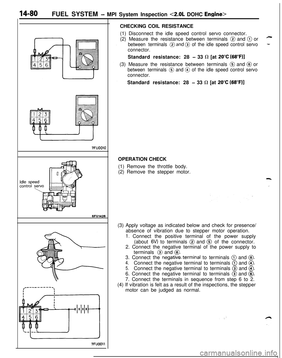
7FUOOllCHECKING COIL RESISTANCE
(1) Disconnect the idle speed control servo connector.
(2) Measure the resistance between terminals
@ and @ or
between terminals @and @ of the idle speed control servo
connector.Standard resistance: 28
- 33 fl [at 20°C (68”F)l(3) Measure the resistance between terminals
@ and @ or
between terminals @ and @ of the idle speed control servo
connector.Standard resistance: 28
- 33 LR [at 20°C (68”F)]OPERATION CHECK
(1) Remove the throttle body.
(2) Remove the stepper motor.
(3) Apply voltage as indicated below and check for presence/
absence of vibration due to stepper motor operation.
1. Connect the positive terminal of the power supply
(about
6V) to terminals @ and @ of the connector.
2. Connect the negative terminal of the power supply to
terminals @ and
@.3. Connect the negativeterminal to terminals
@ and @.
4.Connect the negative terminal to terminals @ and @.
5.Connect the negative terminal to terminals @ and @.6. Connect the negative terminal to terminals
@ and @.7. Connect the terminals in sequence from step 6 to 2.
(4) If vibration is felt as a result of the inspections, the stepper
motor can be judged as normal.
Page 535 of 1216
_-
FUEL SYSTEM - MPI System Inspection <2.0L DOHC Engine>'I4181
OlLO22Z
CONTROL RELAY
INSPECTIONNWWAC
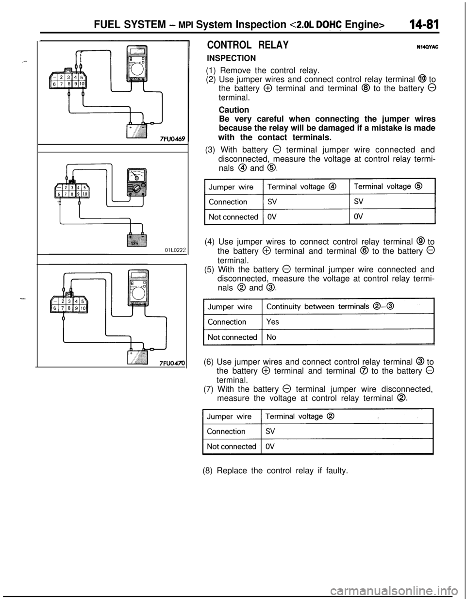
(1) Remove the control relay.
(2) Use jumper wires and connect control relay terminal
@I to
the battery
@ terminal and terminal @ to the battery 0
terminal.Caution
Be very careful when connecting the jumper wires
because the relay will be damaged if a mistake is made
with the contact terminals.
(3) With battery
0 terminal jumper wire connected and
disconnected, measure the voltage at control relay termi-
nals
@I and 0.(4) Use jumper wires to connect control relay terminal
@ to
the battery
@ terminal and terminal @ to the battery 0
terminal.(5) With the battery
@ terminal jumper wire connected and
disconnected, measure the voltage at control relay termi-
nals
@I and 0.
Continuity between terminals 0-0
)(6) Use jumper wires and connect control relay terminal
@ to
the battery
@ terminal and terminal @ to the battery 0
terminal.(7) With the battery
0 terminal jumper wire disconnected,
measure the voltage at control relay terminal
0.
31(8) Replace the control relay if faulty.
Page 536 of 1216
14-82FUEL SYSTEM - MPI System Inspection <2.0L DOHC Engine>
\ \\I \3FUO352
,\ \
\I \3FUO353
,\ ‘\R/
\ \\I \3FUo354
POWER TRANSISTORRefer to GROUP 8
- Ignition System
NlIAcQAl
a-4
AIR CONDITIONER POWER RELAYN14NCl.a -Refer to GROUP 24
- Air Conditioner.
PURGE CONTROL SOLENOID VALVEN14RCKARefer to GROUP 25
- Evaporative Emission Control System.
EGR CONTROL SOLENOID VALVE
N14NCURefer to GROUP 25
- Exhaust Gas Recirculation System.
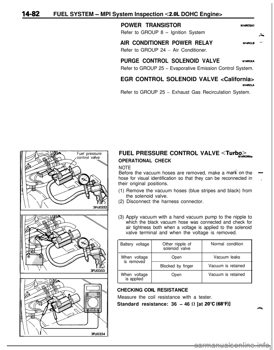
FUEL PRESSURE CONTROL VALVE
NOTEBefore the vacuum hoses are removed, make a mark’on the
-
hose for visual identification so that they can be reconnected in,their original positions.
(1) Remove the vacuum hoses (blue stripes and black) from
the solenoid valve.
(2) Disconnect the harness connector.
(3) Apply vacuum with a hand vacuum pump to the nipple to
which the black vacuum hose was connected and check for
air tightness both when a voltage is applied to the solenoidvalve terminal and when the voltage is removed.
Battery voltageOther nipple of
solenoid valveNormal condition
When voltage
is removed
When voltage
is applied
OpenVacuum leaks
Blocked by fingerVacuum is retained
OpenVacuum is retainedCHECKING
COIL RESISTANCE
Measure the coil resistance with a tester.
Standard resistance: 36
- 46 R [at 20°C (68”F)]
Page 537 of 1216
INJECTORFUEL SYSTEM
- Injector14-83
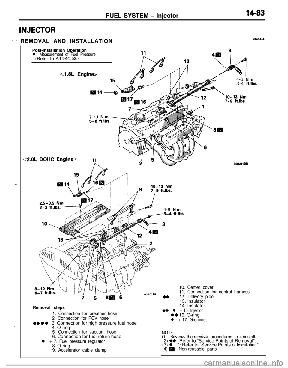
* ‘- REMOVAL AND INSTALLATIONNWSA-A
Post-installation Operation
l Measurement of Fuel Pressure(Refer to P.14-44. 52.)
4.8L Engine><2.0L DOHC
Engilme>11R7-11 Nm
-hl ft.lbs.-zF!
;533i5,b;m-. .-Y-71s4-6 Nma-3-4 ft.lbs.
03AOlSS::,
4*12:
Center cover
Connection for control harness
Delivery pipe
d-- -13. Insulator4-6 Nm
3-4
ft.lbs.
lo-13 Nm
7-9 ft.lbs.Removal steps
1. Connection for breather hose
2. Connection for PCV hose
+e *+3. Connection for high pressure fuel hose
4. O-ring
5. Connection for vacuum hose6. Connection for fuel return hose
l + 7. Fuel pressure regulator8. O-ring
9. Accelerator cable clamp
03AO19014. Insulator
** l + 15. InjectorH 16. O-ringl + 17. Grommet
!PTkeverse the rem&al procedures to reinstall.(2) +* : Refer to “Service Points of Removal”.
(3) l * : Refer to “Service Points of Installatron”(4) m : Non-reusable parts
Page 538 of 1216
14-84FUEL SYSTEM - Injector
03*0095
Delivery pipe03A0095-SERVICE POINTS OF REMOVAL
H4s0m1‘~
3.DISCONNECTION OF THE HIGH PRESSURE FlJFL HOSE /;;
Bleed the residual pressure within the fuel pipe line’& as to~prevent the flow of fuel.
For information concerning the method to be folfowed for
bleeding the residual pressure, refer to
P.14-44.Caution
Cover the hose connection with rags to prevent splash,
of fuel that could be caused by some residual pressure
in the fuel pipe line.
12. REMOVAL OF DELIVERY PIPE/ 15. INJECTOR
Remove the deliver-y pipe (with the injectors attached to it).Caution
Care must be taken, when removing the delivery pipe,
not to drop the injector.
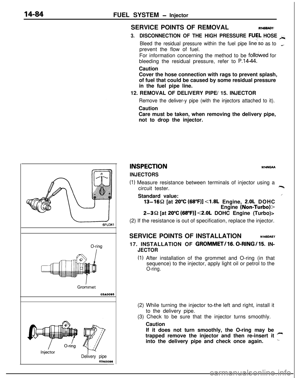
INSPEiZTION
INJECTORS
N14NGAA
(1) Measure resistance between terminals of injector using a
circuit tester.+-%Standard value:
/13-1652 [at
20°C (68”F)] <1.8L Engine, 2.0L DOHC
Engine
(NoniTurbo)>
2-3Q [at 20°C (68”F)] <2.0L DOHC Engine (Turbo)>
(2) If the resistance is out of specification, replace the injector.
SERVICE POINTS OF INSTALLATION
N14SDAEl’17. INSTALLATION OF
GROMMET/lG. 0-RINGI15. IN-
JECTOR
(I) After installation of the grommet and O-ring (in that
sequence) to the injector, apply light oil or petrol to the
O-ring.(2) While turning the injector to.the left and right, install it
to the delivery pipe.
(3) Check to be sure that the injector turns smoothly.
Caution
If it does not turn smoothly, the O-ring may be
~trapped remove the injector and then re-insert it
into the delivery pipe and check once again.
L
Page 539 of 1216
FUEL SYSTEM - Injector/Throttle Body <1.8L Engine>14-85
Delivery pipe
Fuel pres
regulator
O-ringY pipe
O-kg
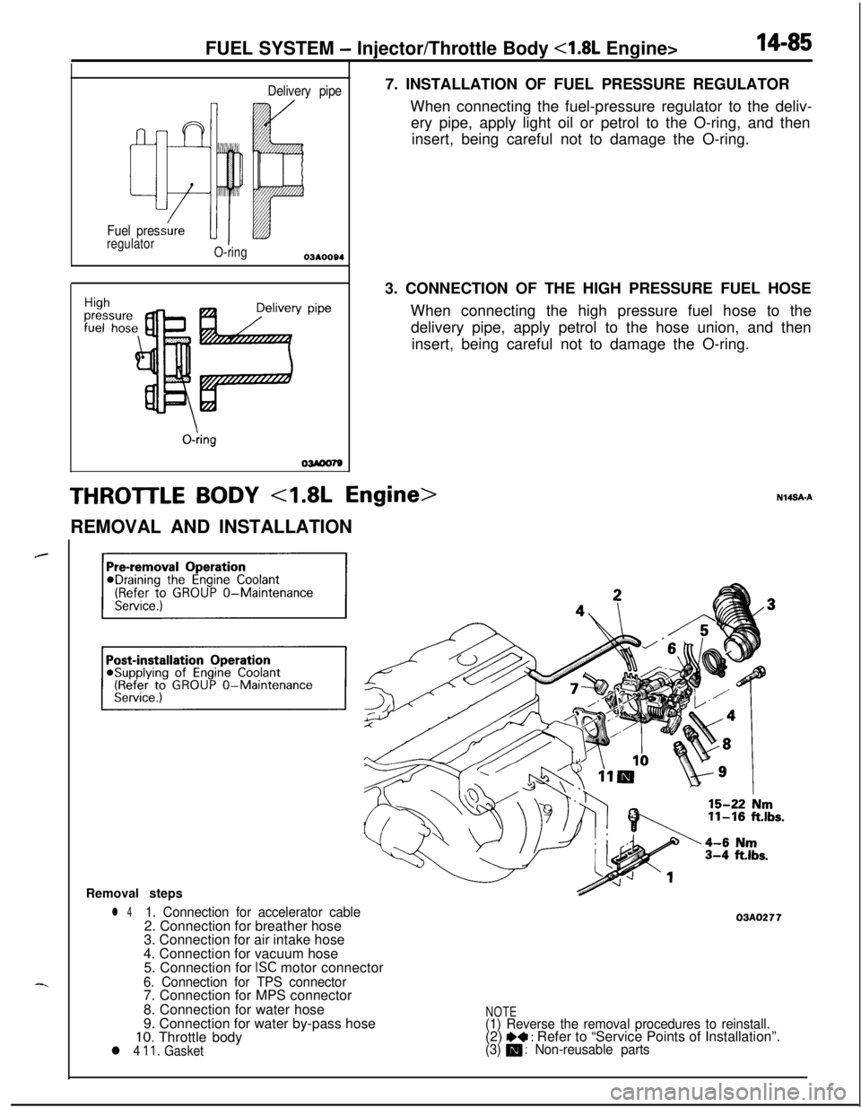
OWOO797. INSTALLATION OF FUEL PRESSURE REGULATOR
When connecting the fuel-pressure regulator to the deliv-
ery pipe, apply light oil or petrol to the O-ring, and then
insert, being careful not to damage the O-ring.
3. CONNECTION OF THE HIGH PRESSURE FUEL HOSE
When connecting the high pressure fuel hose to the
delivery pipe, apply petrol to the hose union, and then
insert, being careful not to damage the O-ring.
THROTTLE BODY 4.8L Engine>REMOVAL AND INSTALLATION
Removal steps
l 41. Connection for accelerator cable2. Connection for breather hose
3. Connection for air intake hose
4. Connection for vacuum hose
5. Connection for
ISC motor connector
6. Connection for TPS connector7. Connection for MPS connector
8. Connection for water hose
9. Connection for water by-pass hose
10. Throttle bodyl 4 11. Gasket
03AO277
NOTE(1) Reverse the removal procedures to reinstall.(2) I)+ : Refer to “Service Points of Installation”.(3) m : Non-reusable parts
Page 540 of 1216
14-86FUEL SYSTEM - Throttle Bodv 4.8L Enaine>
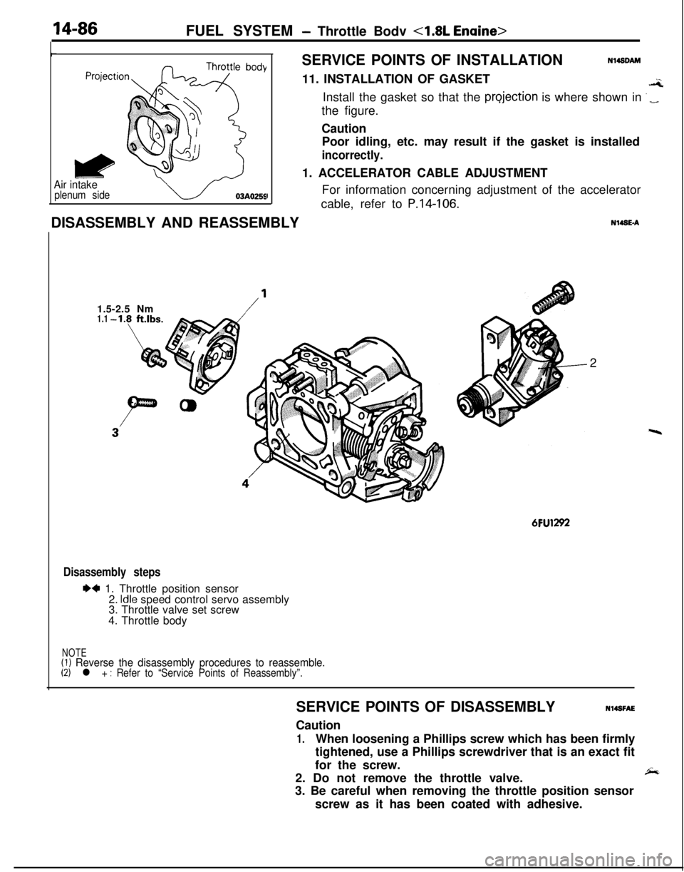
Air intakeplenum sideISERVICE POINTS OF INSTALLATION
Nl4sDAM11. INSTALLATION OF GASKET
.aInstall the gasket so that the
projection is where shown in ‘_the figure.
Caution
Poor idling, etc. may result if the gasket is installed
incorrectly.1. ACCELERATOR CABLE ADJUSTMENT
For information concerning adjustment of the accelerator
cable, refer to
P.14-106.DISASSEMBLY AND REASSEMBLYN14SE-A
1.5-2.5 Nm
/’1.12
6FU1292
Disassembly steps
I)4 1. Throttle position sensor
2. Idle speed control servo assembly
3. Throttle valve set screw
4. Throttle body
NOTE(1) Reverse the disassembly procedures to reassemble.(2) l + : Refer to “Service Points of Reassembly”.SERVICE POINTS OF DISASSEMBLYN14SFAE
Caution
1.When loosening a Phillips screw which has been firmly
tightened, use a Phillips screwdriver that is an exact fit
for the screw.
2. Do not remove the throttle valve.
,&3. Be careful when removing the throttle position sensor
screw as it has been coated with adhesive.