torque MITSUBISHI ECLIPSE 1991 Workshop Manual
[x] Cancel search | Manufacturer: MITSUBISHI, Model Year: 1991, Model line: ECLIPSE, Model: MITSUBISHI ECLIPSE 1991Pages: 1216, PDF Size: 67.42 MB
Page 259 of 1216
COOLING - Service Adjustment Procedures7-m
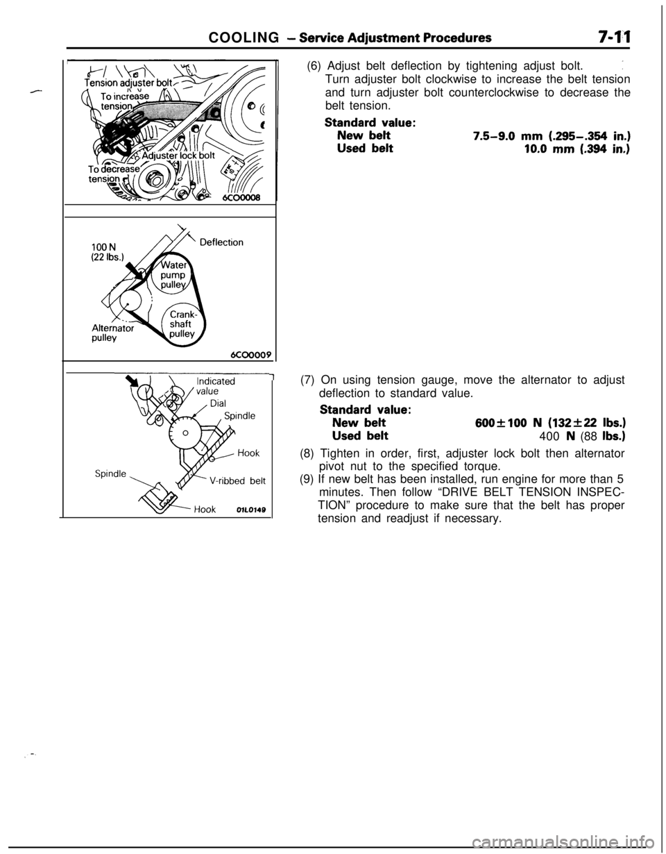
1(6) Adjust belt deflection by tightening adjust bolt.
:Turn adjuster bolt clockwise to increase the belt tension
and turn adjuster bolt counterclockwise to decrease the
belt tension.
Standard value:
New belt7.5-9.0 mm (.295-.354 in.)
Used belt10.0 mm (.394 in.)(7) On using tension gauge, move the alternator to adjust
deflection to standard value.
Standard value:
New belt600+100 N (132f22 Ibs.)
Used belt
400 N (88 Ibs.)(8) Tighten in order, first, adjuster lock bolt then alternator
pivot nut to the specified torque.
(9) If new belt has been installed, run engine for more than 5
minutes. Then follow “DRIVE BELT TENSION INSPEC-
TION” procedure to make sure that the belt has proper
tension and readjust if necessary.
Page 268 of 1216
7-20COOLING - Water Pump <1.8L Engine>
aWater pump*<
l-----r,//
O-ringWater
pipe
04ROO24Identification
mark04lJoo25Alternater
brace
404uoo22
J
SERVICE POINTS OF INSTALLATIONN07ME40a
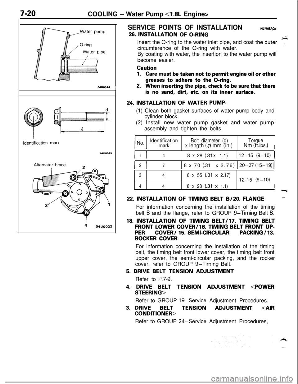
26. INSTALLATION OF O-RINGsInsert the O-ring to the water inlet pipe, and coat the,buter
circumference of the O-ring with water.,
By coating with water, the insertion to the water pump will
become easier.
Caution
1.Care must be taken not to permit engine oil or other
greases to adhere to the O-ring.
2.When inserting the pipe, check to be sure,that there
is no sand, dirt, etc. on its inner surface.
24. INSTALLATION OF WATER PUMP,
(1) Clean both gasket surfaces of water pump body and
cylinder block.
(2) Install new water pump gasket and water pump
assembly and tighten the bolts.
Bolt diameter (d)Torque
x length (e) mm (in.)Nm (ftlbs.)I
I I148 x 28 (.31 x 1.1)112-15 (9-10) 1
I I2
71 8 x 70 (.31 x 2.76) 120-27 (15-19)(
348x55(.31x2.17)12-15(9-10)
448x28(.31x1.1)I
22. INSTALLATION OF TIMING BELT B/20. FLANGE-For information concerning the installation of the timing
belt
B and the flange, refer to GROUP g-Timing Belt B.
18. INSTALLATION OF TIMING BELT/l7. TIMING BELT
FRONT LOWER COVER/lG. TIMING BELT FRONT UP-
PERCOVER/ 15. SEMI-CIRCULARPACKING / 13.
ROCKER COVERFor information concerning the installation of the timing
belt, the timing belt front lower cover, the timing belt front
upper cover, the semi-circular packing, and the rocker
cover, refer to GROUP
g-Timing Belt.
5. DRIVE BELT TENSION ADJUSTMENT
Refer to
P.7-9.
4. DRIVE BELT TENSION ADJUSTMENT
Refer to GROUP
19-Service Adjustment Procedures.
3. DRIVEBELTTENSIONADJUSTMENT
Refer to GROUP
24-Service Adjustment Procedures,
Page 272 of 1216
7-24COOLING - Water Pump <2.0L DOHC Engine>
Identification mark
4lternater brace
6COOOlO
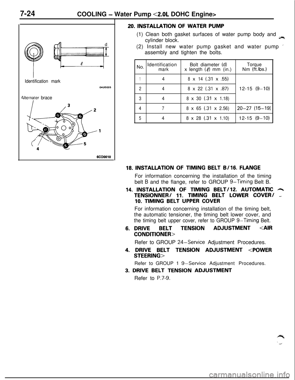
20. INSTALLATION OF WATER PUMP
(1) Clean both gasket surfaces of water pump body and
jir,cylinder block.
(2) Install new water pump gasket and water pump ’
assembly and tighten the bolts.
No, IdentificationBolt diameter (d)Torquemarkx length (I?) mm (in.)Nm (ft.lbs.1
148x14(.31x.55)
248x22(.31x.87)12-15(g-10)
348x30(.31x1.18)
4
78x65(.31x2.56)20-27(15-191
548x28(.31x1.10)12-15(g-10)
18. INSTALLATION OF TIMING BELT B/16. FLANGEFor information concerning the installation of the timing
belt
B and the flange, refer to GROUP g-Timing Belt B.
14. INSTALLATION OF TIMING BELT/lZ. AUTOMATIC 6TENSlONNER/
11. TIMING BELT LOWER COVER/ -
10. TIMING BELT UPPER COVERFor information concerning installation of the timing belt,
the automatic tensioner, the timing belt lower cover, and
the timing belt upper cover, refer to GROUP g-Timing Belt.
6. DRIVEBELT TENSIONADJUSTMENT
Refer to GROUP
24-Service Adjustment Procedures.
4. DRIVE BELT TENSION ADJUSTMENT
Refer to GROUP 1
g-Service Adjustment Procedures.
3. DRIVE BELT TENSION ADJUSTMENT
Refer to
P.7-9.
Page 285 of 1216
9-1
ENGINE
CONTENTSNOSAA-
ENGINE<1.8L
Engine>..................
24CRANKSHAFT, FLYWHEEL AND
DRIVE PLATE................................................
69
CYLINDER
BLOCK.........................................72
CYLINDERHEADANDVALVE
...................
53CYLINDER HEAD GASKET
...........................
36ENGINE ASSEMBLY
.....................................31ENGINE MOUNTING
....................................
28ENGINE ROLL STOPPER
.............................
30FRONT CASE, OIL PUMP AND
SILENT SHAFT
..............................................
58
OILPANANDOILSCREEN........................34
PISTON AND CONNECTING ROD
..............
65ROCKER ARMS AND ROCKER SHAFTS..
..51ROCKER ARMS, ROCKER ARM SHAFTS
AND CAMSHAFT
..........................................48
SERVICE ADJUSTMENT PROCEDURES..
...24TIMING BELT
................................................41TRANSAXLE MOUNTING
............................
29
ENGINE <2.0L DOHC Engine> . . . . . .
74CAMSHAFTS AND CAMSHAFT
OIL SEALS
. . . . . . . . . . . . . . . . . . . . . . . . . . . . . . . . . . . . . . . . . . . . . . . . . . . . .84CAMSHAFTAND
ROCKERARM. . . . . . . . . . . . . . . .109CRANKSHAFT, FLYWHEEL AND
DRIVE PLATE. . . . . . . . . . . . . . . . . . . . . . . . . . . . . . . . . . . . . . . . . . . . . . . .132
CYLINDERBLOCK. . . . . . . . . . . . . . . . . . . . . . . . . . . . . . . . . . . . . . . . .136
CYLINDERHEADANDVALVE
. . . . . . . . . . . . . . . . . . .112CYLINDER HEAD GASKET
...........................90ENGINE ASSEMBLY
.......................................81ENGINE MOUNTING
......................................77ENGINE ROLL STOPPER
...............................
79FRONT CASE, OIL PUMP AND
SILENT SHAFT
..............................................117OIL PAN AND OIL SCREEN
..........................
87
PISTONANDCONNECTING
ROD..............127SERVICE ADJUSTMENT PROCEDURES..
.....76TIMING BELT
................................................
85TRANSAXLE MOUNTING
............................78
GENERALINFORMATION................2
SPECIAL TOOLS...............................20
SPECIFICATIONS...............................8General Specifications
................................8Sealants and Adhesives
.............................19Service Specifications
.................................8Torque Specifications
.................................18
TROUBLESHOOTING........................23Compression Too Low
Connecting Rod Noise/Main Bearing Noise
Excessive Engine Rolling and Vibration
Noisy Valves
Oil Pressure Drop
Oil Pressure Too High
Timing Belt Noise
Page 302 of 1216
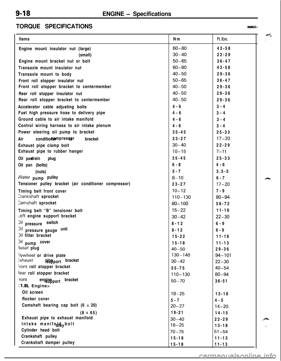
9-18ENGINE - Specifications
TORQUE SPECIFICATIONS
NO9CG-Items
Engine mount insulator nut (large)
(small)
Engine mount bracket nut or bolt
Transaxle mount insulator nut
Transaxle mount to body
Front roll stopper insulator nut
Front roll stopper bracket to centermember
Rear roll stopper insulator nut
Rear roll stopper bracket to centermember
Accelerator cable adjusting bolts
Fuel high pressure hose to delivery pipe
Ground cable to air intake manifold
Control wiring harness to air intake plenum
Power steering oil pump to bracket
Air conditioner to bracketcompressor
Exhaust pipe clamp bolt
Exhaust pipe to rubber hanger
Oil drain plug
panOil (bolts)
pan(nuts)VVater pulley
pump
Tensioner pulley bracket (air conditioner compressor)
Timing belt front coverCrankshaft sprocket
Camshaft sprocket
Timing belt “B” tensioner bolt
-eft engine support bracket3il switch
pressure3il unit
pressure gauge
Iii filter bracket
Iii cover
pumpqelief plug
‘lywheel or drive plate
ixhaust pipe bracket
support
‘rant roll stopper bracket
Iear roll stopper bracket‘rant engine bracket
support
:1.8L Engine>
Oil screen
Rocker cover
Camshaft bearing cap bolt (6 x 20)
(8 x 65)
Exhaust pipe to exhaust manifold
Intake manifold bolt
stay
Cylinder head bolt
Crankshaft pulley
Crankshaft damper pulleyNm
ftlbs.
60-8043-58
30-4022-29
50-6536-47
60-8043-58
40-5029-36
50-6536-47
40-5029-36
40-5029-36
40-5029-36
4-63-4
4-6
3-4
4-6
3-4
4-6
3-4
35-45
25-33
23-27
17-20
30-4022-29
10-157-l 135-45
25-33
6-84-6
5-73.5-5
8-106-7
23-27
17-20
10-127-9
110-13080-94
80-10058-72
15-2211-16
30-4222-308-126-9
8-126-9
15-2211-16
15-1811-13
40-5029-36
130-14094-101
30-4222-3055-75
40-54
110-13080-94
50-7036-51
18-2513-18
5-74-5
20-2714-2019-21
14-15
30-4022-29
18-2513-18
70-7551-5415-1811-13
15-1811-13
Page 341 of 1216
ENGINE <1.8L Engine> - Cylinder Head and Valve9-57
Enamel-
coating
sideSpring
retainerStem seal
Spring- seat
3EN324intake side
3EN315Front of engine
I,Exhaust side
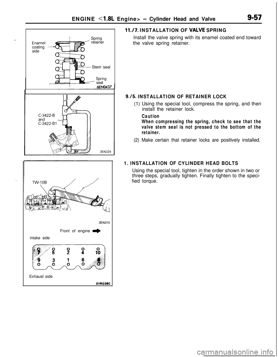
11./7. INSTALLATION OF VALVE SPRINGInstall the valve spring with its enamel coated end toward
the valve spring retainer.
9.15. INSTALLATION OF RETAINER LOCK(1) Using the special tool, compress the spring, and then
install the retainer lock.
Caution
When compressing the spring, check to see that the
valve stem seal is not pressed to the bottom of the
retainer.
(2) Make certain that retainer locks are positively installed.
1. INSTALLATION OF CYLINDER HEAD BOLTSUsing the special tool, tighten in the order shown in two or
three steps, gradually tighten. Finally tighten to the speci-
fied torque.
Page 354 of 1216
ENGINE <1.8L Engine> -Crankshaft, Flywheel and Drive Plate
3EN055
6EN043
1 EN067
MAIN BEARINGS AND CONNECTING ROD BEARINGSVisually inspect each bearing for peeling, melt, seizure and
improper contact. Replace the faulty bearings.
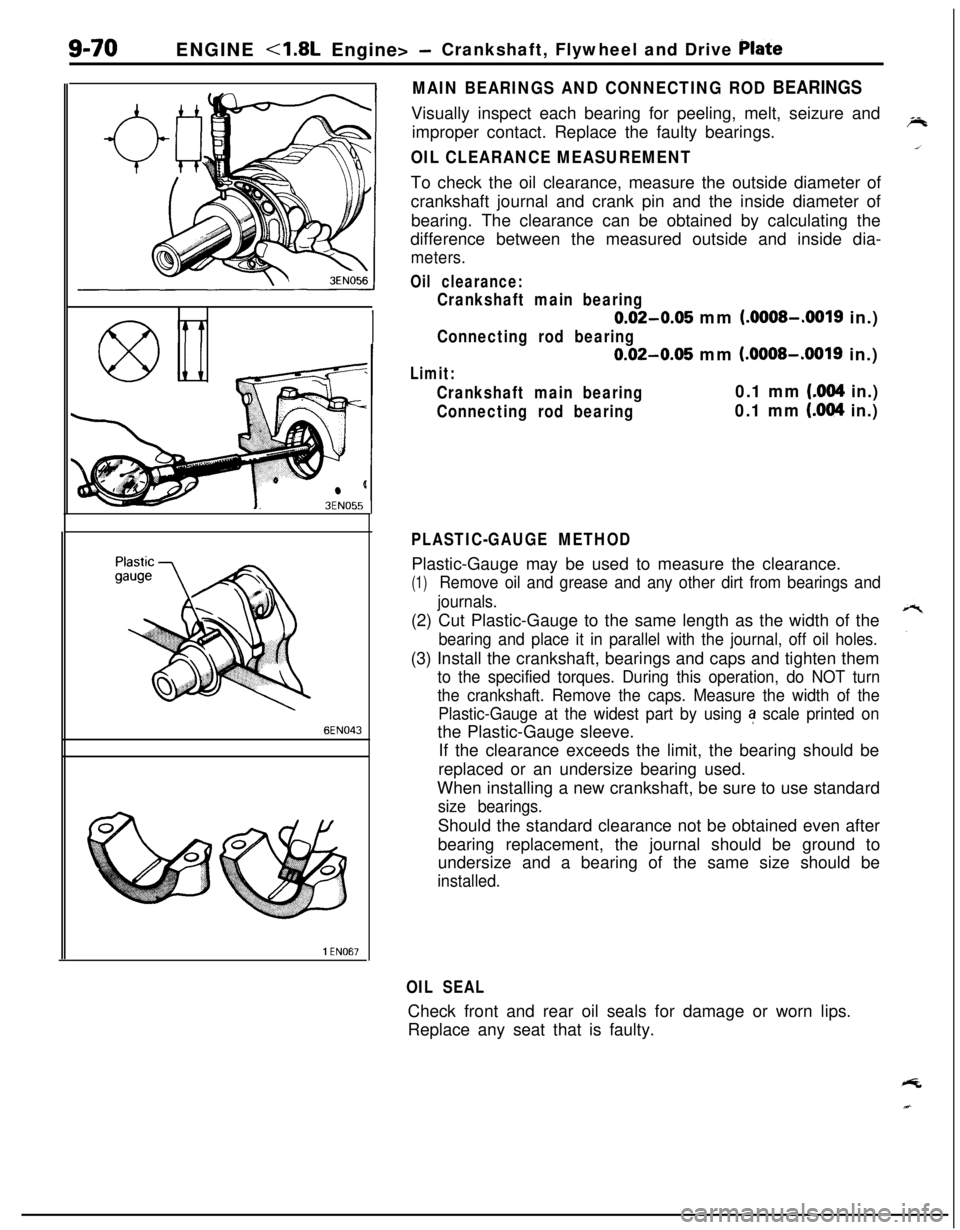
OIL CLEARANCE MEASUREMENTTo check the oil clearance, measure the outside diameter of
crankshaft journal and crank pin and the inside diameter of
bearing. The clearance can be obtained by calculating the
difference between the measured outside and inside dia-
meters.
Oil clearance:
Crankshaft main bearing
0.02-0.05 mm (.OOOS-.0019 in.)
Connecting rod bearing
0.02-0.05 mm (.OOOS-.0019 in.)
Limit:
Crankshaft main bearing0.1 mm (.004 in.)
Connecting rod bearing0.1 mm (.004 in.)
PLASTIC-GAUGE METHODPlastic-Gauge may be used to measure the clearance.
(1)Remove oil and grease and any other dirt from bearings and
journals.(2) Cut Plastic-Gauge to the same length as the width of the
bearing and place it in parallel with the journal, off oil holes.(3) Install the crankshaft, bearings and caps and tighten them
to the specified torques. During this operation, do NOT turn
the crankshaft. Remove the caps. Measure the width of the
Plastic-Gauge at the widest part by using
a scale printed onthe Plastic-Gauge sleeve.
If the clearance exceeds the limit, the bearing should be
replaced or an undersize bearing used.
When installing a new crankshaft, be sure to use standard
size bearings.Should the standard clearance not be obtained even after
bearing replacement, the journal should be ground to
undersize and a bearing of the same size should be
installed.
OIL SEALCheck front and rear oil seals for damage or worn lips.
Replace any seat that is faulty.
Page 370 of 1216
9-86ENGINE <2.0L DOHC Engine> -Camshafts and Camshaft Oil Seals
rMD998306qil seal
coatithe
mrenceof the guide.
6EN612Matingmark atMating mark at
llA0361Semi-circular packing
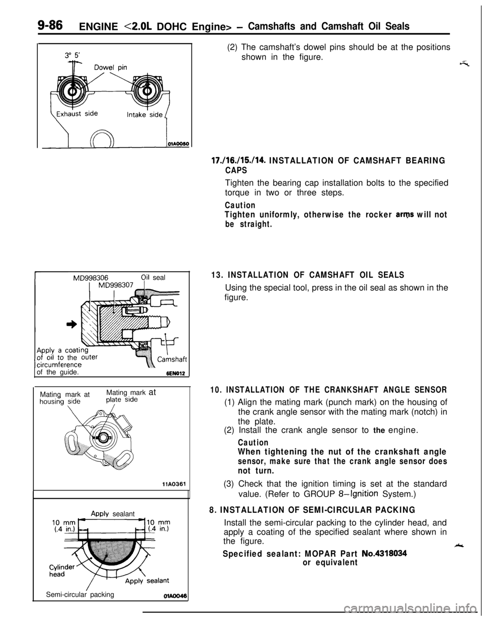
Awlv sealant(2) The camshaft’s dowel pins should be at the positions
shown in the figure.
17./16./15./14. INSTALLATION OF CAMSHAFT BEARING
CAPSTighten the bearing cap installation bolts to the specified
torque in two or three steps.
Caution
Tighten uniformly, otherwise the rocker arms will not
be straight.
13. INSTALLATION OF CAMSHAFT OIL SEALSUsing the special tool, press in the oil seal as shown in the
figure.
_-‘7
10. INSTALLATION OF THE CRANKSHAFT ANGLE SENSOR(1) Align the mating mark (punch mark) on the housing of
the crank angle sensor with the mating mark (notch) in
the plate.
(2) Install the crank angle sensor to the engine.
Caution
When tightening the nut of the crankshaft angle
sensor, make sure that the crank angle sensor does
not turn.(3) Check that the ignition timing is set at the standard
value. (Refer to GROUP
8-Ignition System.)
8. INSTALLATION OF SEMI-CIRCULAR PACKINGInstall the semi-circular packing to the cylinder head, and
apply a coating of the specified sealant where shown in
the figure.
Ak
Specified sealant: MOPAR Part No.4318034
or equivalent
Page 377 of 1216
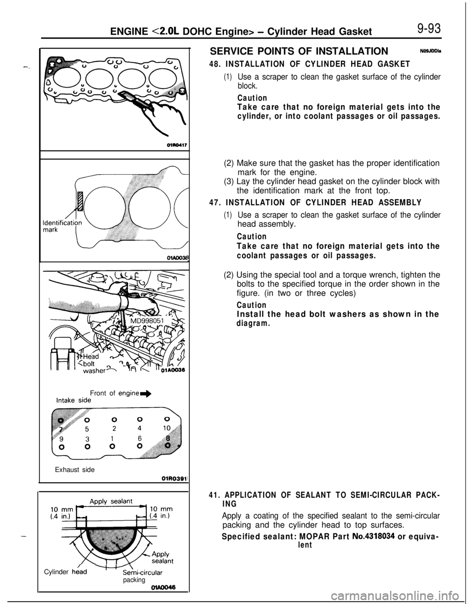
ENGINE <2.0L DOHC Engine> - Cylinder Head Gasket9-93
DlADD3fFront of
engine+Exhaust side
OlR0391Cylinder
he/d-Ani-circularpackingSERVICE POINTS OF INSTALLATIONNOSJDDls
48. INSTALLATION OF CYLINDER HEAD GASKET
(1)Use a scraper to clean the gasket surface of the cylinder
block.
Caution
Take care that no foreign material gets into the
cylinder, or into coolant passages or oil passages.(2) Make sure that the gasket has the proper identification
mark for the engine.
(3) Lay the cylinder head gasket on the cylinder block with
the identification mark at the front top.
47. INSTALLATION OF CYLINDER HEAD ASSEMBLY
(1)Use a scraper to clean the gasket surface of the cylinderhead assembly.
Caution
Take care that no foreign material gets into the
coolant passages or oil passages.(2) Using the special tool and a torque wrench, tighten the
bolts to the specified torque in the order shown in the
figure. (in two or three cycles)
Caution
Install the head bolt washers as shown in the
diagram.
41. APPLICATION OF SEALANT TO SEMI-CIRCULAR PACK-
ING
Apply a coating of the specified sealant to the semi-circularpacking and the cylinder head to top surfaces.
Specified sealant: MOPAR Part No.4318034 or equiva-
lent
Page 386 of 1216
S-102ENGINE <2.0L DOHC Engine> - Timing Belt
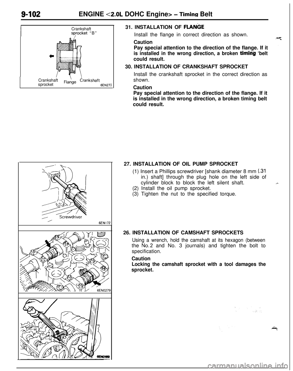
Crankshaftsyocket “B”
Crankshaft
sprocketdrankshaft 6fN272
6EN I1231. INSTALLATION OF
FLANGEInstall the flange in correct direction as shown.
Caution
Pay special attention to the direction of the flange. If it
is installed in the wrong direction, a broken timiiig ‘beltcould result.
30. INSTALLATION OF CRANKSHAFT SPROCKET
Install the crankshaft sprocket in the correct direction as
shown.Caution
Pay special attention to the direction of the flange. If it
is installed in the wrong direction, a broken timing belt
could result.
27. INSTALLATION OF OIL PUMP SPROCKET
(1) Insert a Phillips screwdriver [shank diameter 8 mm
(.31in.) shaft] through the plug hole on the left side of
cylinder block to block the left silent shaft.
(2) Install the oil pump sprocket.
(3) Tighten the nut to the specified torque.
26. INSTALLATION OF CAMSHAFT SPROCKETS
Using a wrench, hold the camshaft at its hexagon (betweenthe
No.2 and No. 3 journals) and tighten the bolt to
specification.Caution
Locking the camshaft sprocket with a tool damages the
sprocket.