MITSUBISHI ENDEAVOR 2004 Service Repair Manual
Manufacturer: MITSUBISHI, Model Year: 2004, Model line: ENDEAVOR, Model: MITSUBISHI ENDEAVOR 2004Pages: 3870, PDF Size: 98.47 MB
Page 1791 of 3870
NO: Either repair or replace the antenna assembly. The radio should
sound normally.
INSPECTION PROCEDURE 18: Poor Reception. DIAGNOSIS
STEP 1. Check the state of the antenna.
Q: Is the mast antenna assembled?
YES: Go to Step 2.
NO: Assemble the mast antenna. Check that a poor reception is resolved.
STEP 2. Check to see if inspections are taking place is an area exposed to
special electric fields.
Q: Are inspections taking place under special electric field conditions
(underground garage, inside a building, etc.)?
YES: Go to Step 3.
NO: Go to Step 4 .
STEP 3. Move the vehicle and check the radio.
Move the vehicle to a good reception area that is not exposed to special electric
fields.
Q: Is reception of the strongest radio frequency possible within the area?
YES: Check that a poor reception is resolved.
NO: Go to Step 4.
STEP 4. Tune the radio, and then check it.
Q: Did the sensitivity improve after tuning?
YES: Check that a poor reception is resolved.
NO: Go to Step 5.
STEP 5. Check with several broadcastin
g stations
.
2004 Mitsubishi Endeavor LS
2004 BODY & ACCESSORIES Radio With Tape Player & Cd Player - Endeavor
Page 1792 of 3870
Q: Is the abnormality in reception generated only within a certain range?
YES: Check that a poor reception is resolved.
NO: Go to Step 6.
STEP 6. Check the connection of the antenna plug and radio and CD
player.
Q: Is the antenna plug thoroughly connected to the radio and CD player?
YES: Go to Step 7.
NO: Thoroughly connect the antenna plug and the radio and CD player.
Check that a poor reception is resolved.
STEP 7. Check by replacing radio and CD player.
Q: Do the other radio and CD player work normally?
YES: Either repair or replace the original radio and CD player. Check that
a poor reception is resolved.
NO: Either re
pair or re
place the antenna assembl
y. Check that a
poor
NOTE: Two types of noise are addressed in this procedure,
multipath and fading noise. The frequency of FM waves
is extremely high. This makes them susceptible to
effects from geological formations and buildings. These
effects disrupt the broadcast signal and obstruct
reception in many ways.
Multipath noise is the echo that occurs when the
broadcast signal is reflected by a large obstruction
and enters the receiver with a slight time delay
relative to the direct signal (repetitious buzzing). A fading or buzzing noise may occur when the
broadcast beam is disrupted by obstructing objects
and the signal strength fluctuates within a narrow
range.
2004 Mitsubishi Endeavor LS
2004 BODY & ACCESSORIES Radio With Tape Player & Cd Player - Endeavor
Page 1793 of 3870
reception is resolved.
INSPECTION PROCEDURE 19: Distortion on AM and/or FM. DIAGNOSIS
STEP 1. Check the level of distortion.
Q: How much distortion is there?
Occasional distortion : Go to Step 2.
Constant distortion : Go to Step 3 .
STEP 2. Check the location of the distortion.
Q: Is there distortion when the vehicle is near the radio station?
YES: The antenna is receiving too strong a signal.
NO: Go to Step 3.
STEP 3. Check the wires at each speaker.
Q: Are the speaker wires contacting the paper speaker cone?
YES: Move the speaker wires away from the paper speaker cone. The
speaker should now be free of distortion.
NO: Go to Step 4.
STEP 4. Remove the speakers, and check the paper cone for foreign
material or damage.
Q: Is there foreign material or damage on the paper cone of the speaker?
YES: Repair or replace the speakers. The speaker should now be free of
distortion.
NO: Go to Step 5.
STEP 5. Check for distortion with the speaker installed.
Q: Does a distortion occur?
2004 Mitsubishi Endeavor LS
2004 BODY & ACCESSORIES Radio With Tape Player & Cd Player - Endeavor
Page 1794 of 3870
YES: Install the speaker securely. The speaker should now be free of
distortion.
NO: Repair or replace the radio and CD player. The speaker should now
be free of distortion.
INSPECTION PROCEDURE 20: Distortion on FM Only. DIAGNOSIS
STEP 1. Check that the distortion is present when the radio is tuned to
another station.
Q: Does the distortion persist when the radio is tuned to another station?
YES: Go to Step 2.
NO: The signal from that station is too weak.
STEP 2. Relocate the reception area and check the radio.
Q: When relocating the reception area does the distortion increase or
decrease?
YES: The cause may be multipath or fading noise. Multipath noise is the
echo that occurs when the broadcast signal is reflected by a large
obstruction and enters the receiver with a slight time delay relative to the
direct signal (repetitious buzzing). A fading or buzzing noise may occur
when the broadcast beam is disrupted by obstructing objects and the signal
strength fluctuates within a narrow range.
NO: Replace the radio and CD player. Check that a distortion is resolved.
INSPECTION PROCEDURE 21: Auto Select Function Inoperative, too Few Automatic Stations are Selected. DIAGNOSIS
STEP 1. Check the state of the antenna.
Q: Is the mast antenna assembled?
YES: Go to Step 2.
2004 Mitsubishi Endeavor LS
2004 BODY & ACCESSORIES Radio With Tape Player & Cd Player - Endeavor
Page 1795 of 3870
NO: Assemble the mast antenna. The auto-select function should operate
normally.
STEP 2. Check the number of radio stations.
Q: Are there sufficient numbers of radio stations within the area?
YES: Go to Step 3.
NO: Go to Step 4 .
STEP 3. Check the distance from the transmission antenna.
Q: Is there a transmission antenna within a range of 2 miles?
YES: Go to Step 5 .
NO: Go to Step 4.
STEP 4. The check if there are not that many radio stations and when
there is no transmission antenna in the vicinity.
Execute automatic selection and check to see that the strongest radio frequency
is receivable within the area.
Q: Is reception of the strongest radio frequency possible within the area?
YES: There is no action to be taken.
NO: Go to Step 5.
STEP 5. Check to see if inspections are taking place is an area exposed to
special electric fields.
Q: Are inspections taking place under special electric field conditions
(underground garage, inside a building, etc.)?
YES: Go to Step 6.
NO: Go to Step 7 .
STEP 6. Relocate and check.
Automaticall
y receive in a
good rece
ption area tha
t is not ex
posed to s
pecial
2004 Mitsubishi Endeavor LS
2004 BODY & ACCESSORIES Radio With Tape Player & Cd Player - Endeavor
Page 1796 of 3870
electric fields.
Q: Is reception of the strongest radio frequency possible within the area?
YES: There is no action to be taken.
NO: Go to Step 7.
STEP 7. Check the connection of the antenna feeder cable and radio and
CD player.
Q: Is the antenna feeder cable thoroughly connected to the radio and CD
player?
YES: Repair or replace the radio and CD player. The auto-select function
should operate normally.
NO: Thoroughly connect the antenna feeder cable and the radio and CD
player. The auto-select function should operate normally.
INSPECTION PROCEDURE 22: Preset Stations are Erased
.
2004 Mitsubishi Endeavor LS
2004 BODY & ACCESSORIES Radio With Tape Player & Cd Player - Endeavor
Page 1797 of 3870
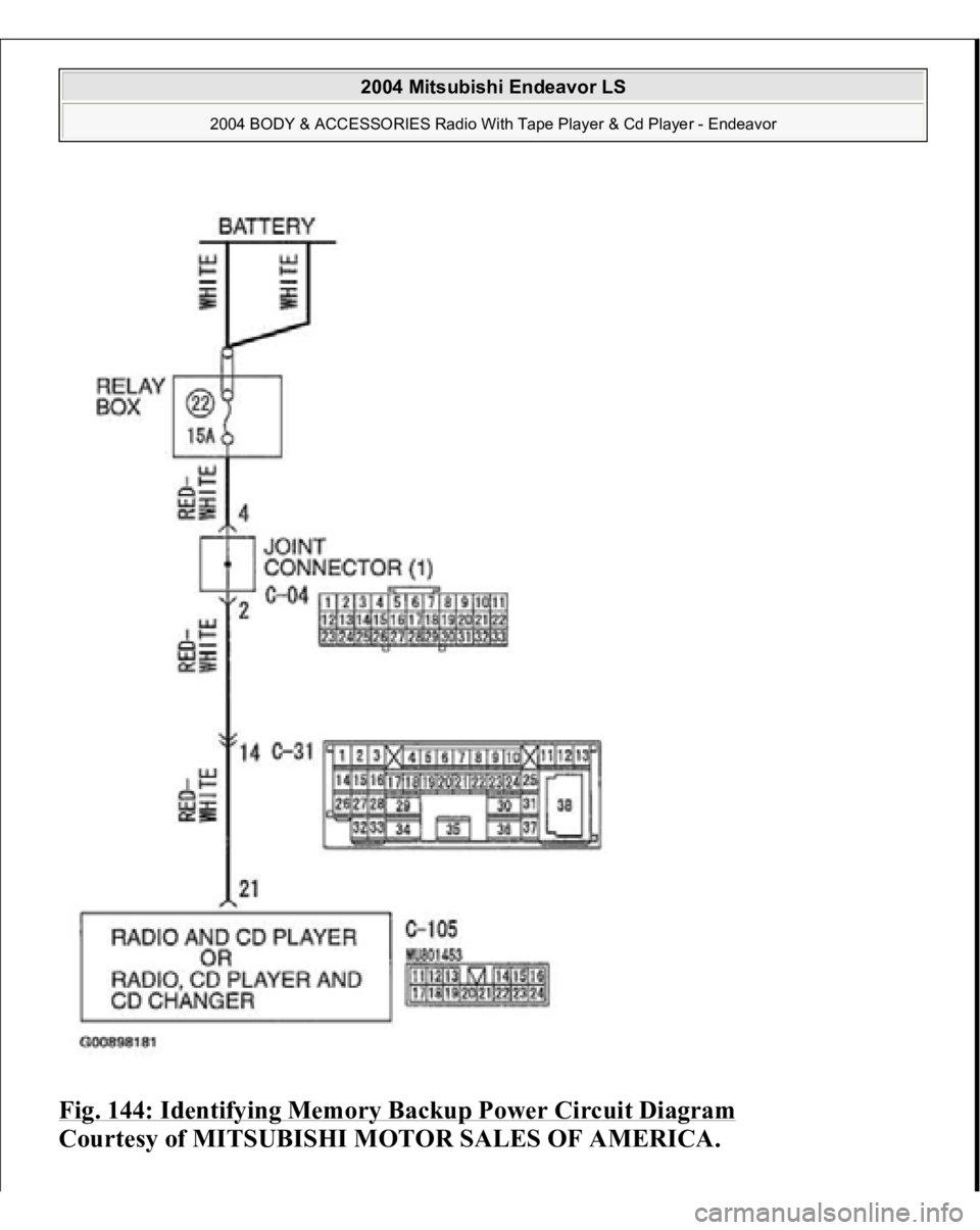
Fig. 144: Identifying Memory Backup Power Circuit Diagram
Courtesy of MITSUBISHI MOTOR SALES OF AMERICA.
2004 Mitsubishi Endeavor LS
2004 BODY & ACCESSORIES Radio With Tape Player & Cd Player - Endeavor
Page 1798 of 3870
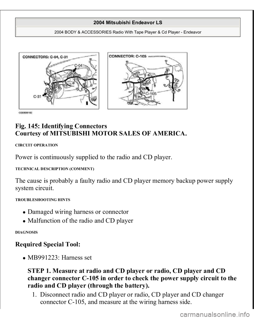
Fig. 145: Identifying Connectors
Courtesy of MITSUBISHI MOTOR SALES OF AMERICA.
CIRCUIT OPERATION Power is continuously supplied to the radio and CD player. TECHNICAL DESCRIPTION (COMMENT) The cause is probably a faulty radio and CD player memory backup power supply
system circuit. TROUBLESHOOTING HINTS
Damaged wiring harness or connector Malfunction of the radio and CD player
DIAGNOSIS Required Special Tool:
MB991223: Harness set
STEP 1. Measure at radio and CD player or radio, CD player and CD
changer connector C-105 in order to check the power supply circuit to the
radio and CD player (through the battery).
1. Disconnect radio and CD player or radio, CD player and CD changer
connector
C-105, and measure at the wirin
g harness side.
2004 Mitsubishi Endeavor LS
2004 BODY & ACCESSORIES Radio With Tape Player & Cd Player - Endeavor
Page 1799 of 3870
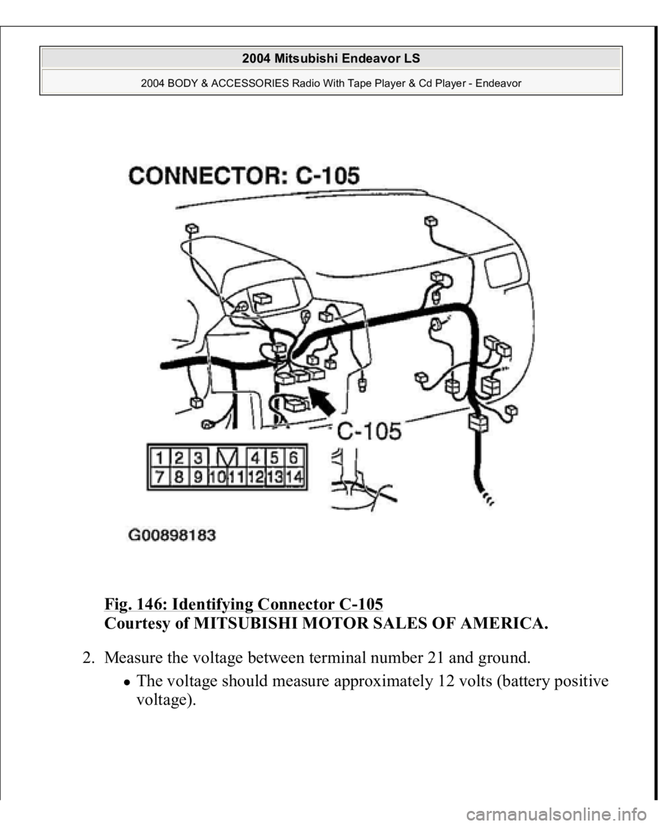
Fig. 146: Identifying Connector C
-105
Courtesy of MITSUBISHI MOTOR SALES OF AMERICA.
2. Measure the voltage between terminal number 21 and ground.
The voltage should measure approximately 12 volts (battery positive
voltage).
2004 Mitsubishi Endeavor LS
2004 BODY & ACCESSORIES Radio With Tape Player & Cd Player - Endeavor
Page 1800 of 3870
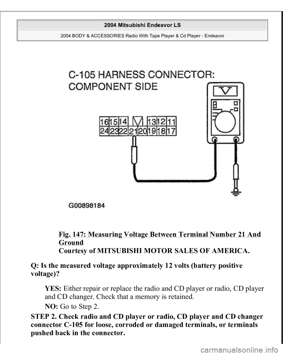
Fig. 147: Measuring Voltage Between Terminal Number 21 And Ground
Courtesy of MITSUBISHI MOTOR SALES OF AMERICA.
Q: Is the measured voltage approximately 12 volts (battery positive
voltage)?
YES: Either repair or replace the radio and CD player or radio, CD player
and CD changer. Check that a memory is retained.
NO: Go to Step 2.
STEP 2. Check radio and CD player or radio, CD player and CD changer
connector C-105 for loose, corroded or damaged terminals, or terminals
pushed back in the connector.
2004 Mitsubishi Endeavor LS
2004 BODY & ACCESSORIES Radio With Tape Player & Cd Player - Endeavor