MITSUBISHI ENDEAVOR 2004 Service Repair Manual
ENDEAVOR 2004
MITSUBISHI
MITSUBISHI
https://www.carmanualsonline.info/img/19/57105/w960_57105-0.png
MITSUBISHI ENDEAVOR 2004 Service Repair Manual
Trending: Ac pressure switch, oil level, p0340, Change cooling, service indicator, stop start, wipers
Page 1851 of 3870
2004 DRIVELINE/AXLES
Front Axle Hub & Axle Shafts - Endeavor
FRONT AXLE HUB ASSEMBLY REMOVAL AND INSTALLATION
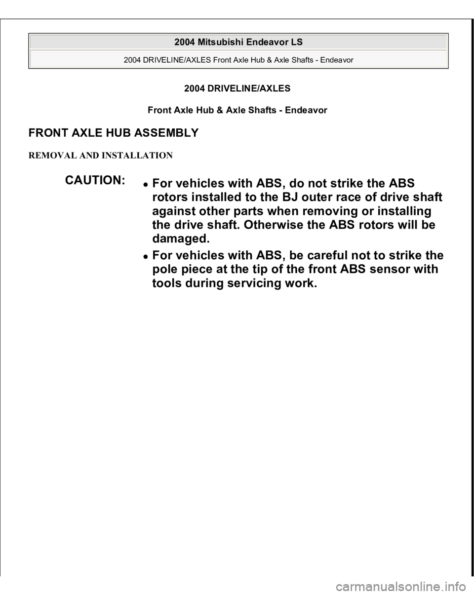
CAUTION:
For vehicles with ABS, do not strike the ABS
rotors installed to the BJ outer race of drive shaft
against other parts when removing or installing
the drive shaft. Otherwise the ABS rotors will be
damaged. For vehicles with ABS, be careful not to strike the
pole piece at the tip of the front ABS sensor with
tools during servicing work.
2004 Mitsubishi Endeavor LS
2004 DRIVELINE/AXLES Front Axle Hub & Axle Shafts - Endeavor
2004 Mitsubishi Endeavor LS
2004 DRIVELINE/AXLES Front Axle Hub & Axle Shafts - Endeavor
Page 1852 of 3870
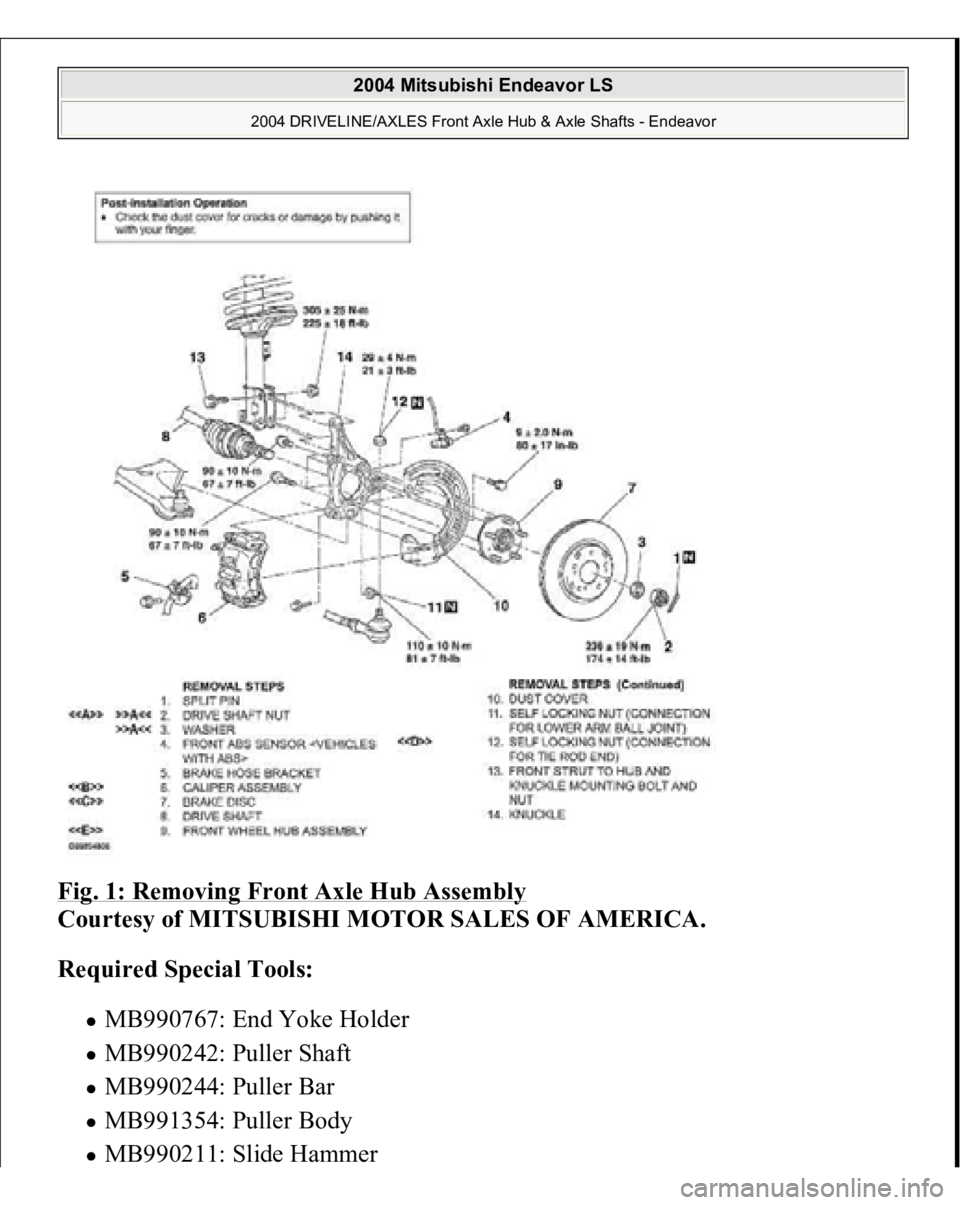
Fig. 1: Removing Front Axle Hub Assembly
Courtesy of MITSUBISHI MOTOR SALES OF AMERICA.
Required Special Tools:
MB990767: End Yoke Holder MB990242: Puller Shaft MB990244: Puller Bar MB991354: Puller Body MB990211: Slide Hammer
2004 Mitsubishi Endeavor LS
2004 DRIVELINE/AXLES Front Axle Hub & Axle Shafts - Endeavor
Page 1853 of 3870
MB991897: Ball Joint Remover
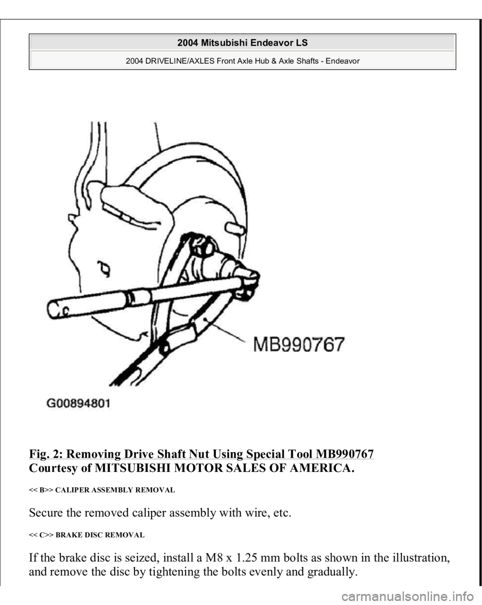
REMOVAL SERVICE POINTS << A>> DRIVE SHAFT NUT REMOVAL Use special tool MB990767 to fix the hub and remove the drive shaft nut.
CAUTION: Do not apply pressure to wheel bearing by the
vehicle weight to avoid possible damage when drive
shaft nut is loosened.
2004 Mitsubishi Endeavor LS
2004 DRIVELINE/AXLES Front Axle Hub & Axle Shafts - Endeavor
Page 1854 of 3870
Fig. 2: Removing Drive Shaft Nut Using Special Tool MB990767
Courtesy of MITSUBISHI MOTOR SALES OF AMERICA.
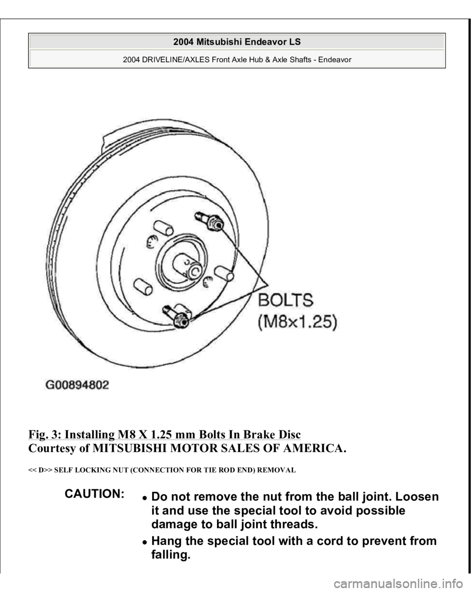
<< B>> CALIPER ASSEMBLY REMOVAL Secure the removed caliper assembly with wire, etc. << C>> BRAKE DISC REMOVAL If the brake disc is seized, install a M8 x 1.25 mm bolts as shown in the illustration,
and remove the disc b
y tightenin
g the bolts evenl
y and
graduall
y.
2004 Mitsubishi Endeavor LS
2004 DRIVELINE/AXLES Front Axle Hub & Axle Shafts - Endeavor
Page 1855 of 3870
Fig. 3: Installing M8 X 1.25 mm Bolts In Brake Disc
Courtesy of MITSUBISHI MOTOR SALES OF AMERICA.
<< D>> SELF LOCKING NUT (CONNECTION FOR TIE ROD END) REMOVAL
CAUTION:
Do not remove the nut from the ball joint. Loosen
it and use the special tool to avoid possible
damage to ball joint threads. Hang the special tool with a cord to prevent from
falling.
2004 Mitsubishi Endeavor LS
2004 DRIVELINE/AXLES Front Axle Hub & Axle Shafts - Endeavor
Page 1856 of 3870
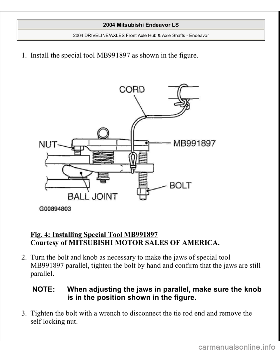
1. Install the special tool MB991897 as shown in the figure.
Fig. 4: Installing Special Tool MB991897
Courtesy of MITSUBISHI MOTOR SALES OF AMERICA.
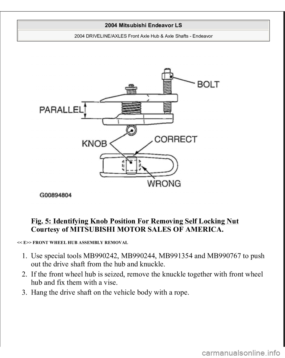
2. Turn the bolt and knob as necessary to make the jaws of special tool
MB991897 parallel, tighten the bolt by hand and confirm that the jaws are still
parallel.
3. Tighten the bolt with a wrench to disconnect the tie rod end and remove the
self lockin
g nut.
NOTE: When adjusting the jaws in parallel, make sure the knob
is in the position shown in the figure.
2004 Mitsubishi Endeavor LS
2004 DRIVELINE/AXLES Front Axle Hub & Axle Shafts - Endeavor
Page 1857 of 3870
Fig. 5: Identifying Knob Position For Removing Self Locking Nut
Courtesy of MITSUBISHI MOTOR SALES OF AMERICA.
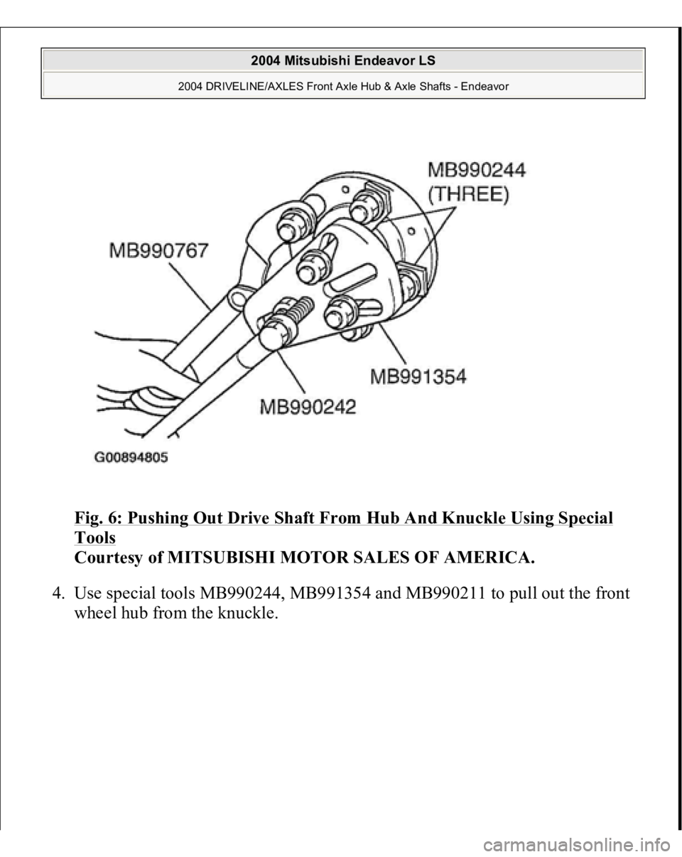
<< E>> FRONT WHEEL HUB ASSEMBLY REMOVAL 1. Use special tools MB990242, MB990244, MB991354 and MB990767 to push
out the drive shaft from the hub and knuckle.
2. If the front wheel hub is seized, remove the knuckle together with front wheel
hub and fix them with a vise.
3. Han
g the drive shaft on the vehicle bod
y with a ro
pe.
2004 Mitsubishi Endeavor LS
2004 DRIVELINE/AXLES Front Axle Hub & Axle Shafts - Endeavor
Page 1858 of 3870
Fig. 6: Pushing Out Drive Shaft From Hub And Knuckle Using Special Tools
Courtesy of MITSUBISHI MOTOR SALES OF AMERICA.
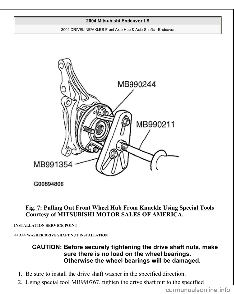
4. Use special tools MB990244, MB991354 and MB990211 to pull out the front
wheel hub from the knuckle.
2004 Mitsubishi Endeavor LS
2004 DRIVELINE/AXLES Front Axle Hub & Axle Shafts - Endeavor
Page 1859 of 3870
Fig. 7: Pulling Out Front Wheel Hub From Knuckle Using Special Tools
Courtesy of MITSUBISHI MOTOR SALES OF AMERICA.
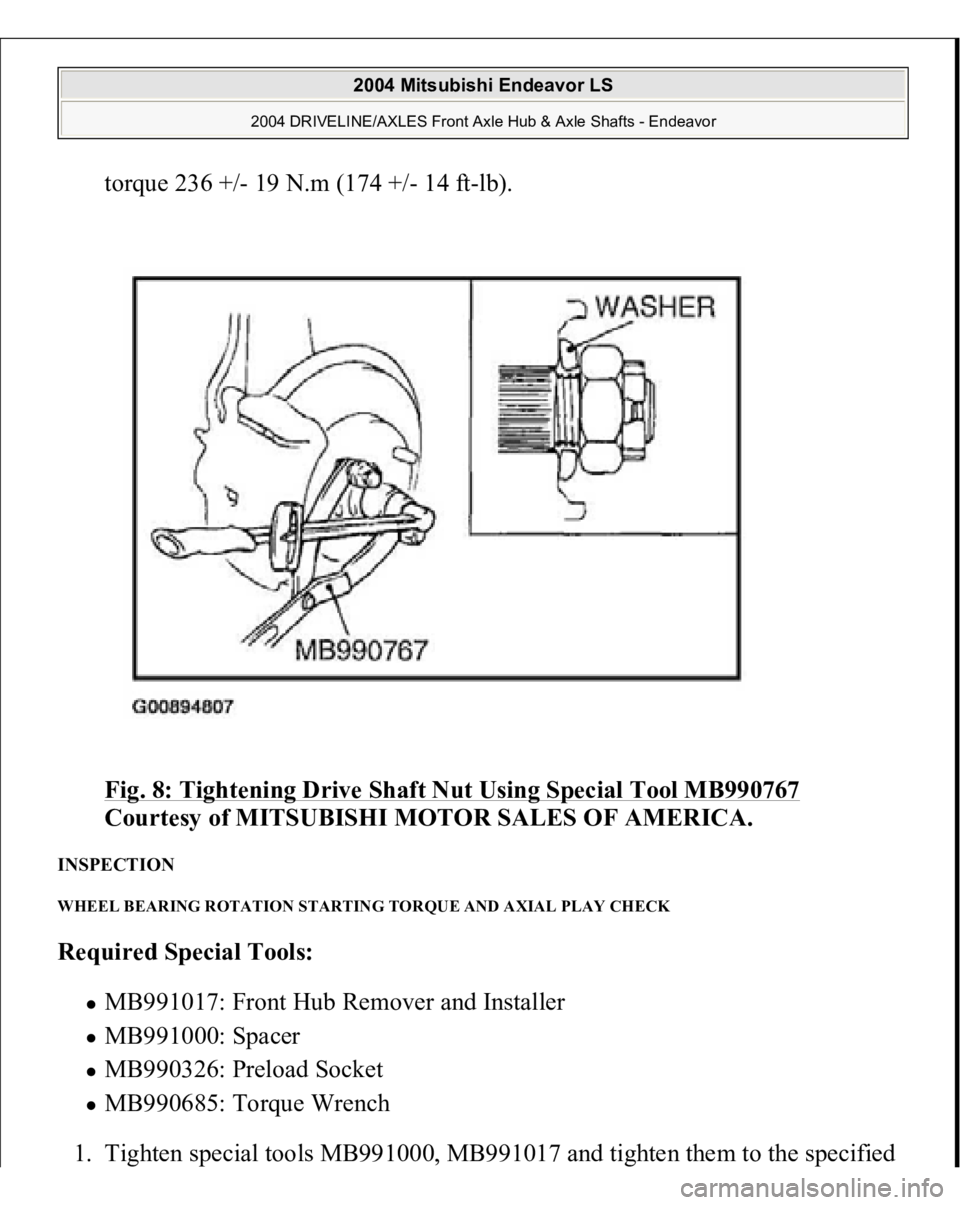
INSTALLATION SERVICE POINT << A>> WASHER/DRIVE SHAFT NUT INSTALLATION 1. Be sure to install the drive shaft washer in the specified direction.
2. Usin
g special tool MB990767
, tighten the drive sha
ft nut to the s
pecified
CAUTION: Before securely tightening the drive shaft nuts, make
sure there is no load on the wheel bearings.
Otherwise the wheel bearings will be damaged.
2004 Mitsubishi Endeavor LS
2004 DRIVELINE/AXLES Front Axle Hub & Axle Shafts - Endeavor
Page 1860 of 3870
torque 236 +/- 19 N.m (174 +/- 14 ft-lb).
Fig. 8: Tightening Drive Shaft Nut Using Special Tool MB990767
Courtesy of MITSUBISHI MOTOR SALES OF AMERICA.
INSPECTION WHEEL BEARING ROTATION STARTING TORQUE AND AXIAL PLAY CHECK Required Special Tools:
MB991017: Front Hub Remover and Installer MB991000: Spacer MB990326: Preload Socket MB990685: Torque Wrench
1. Tighten s
pecial tools MB991000, MB991017 and ti
ghten them to the s
pecified
2004 Mitsubishi Endeavor LS
2004 DRIVELINE/AXLES Front Axle Hub & Axle Shafts - Endeavor
Trending: sunroof jam, AUX, brake fluid, Seat, diagnosis, turn off alarm, interval
