Side MITSUBISHI LANCER 2005 Owners Manual
[x] Cancel search | Manufacturer: MITSUBISHI, Model Year: 2005, Model line: LANCER, Model: MITSUBISHI LANCER 2005Pages: 788, PDF Size: 45.98 MB
Page 314 of 788
DOOR
BODY42-36
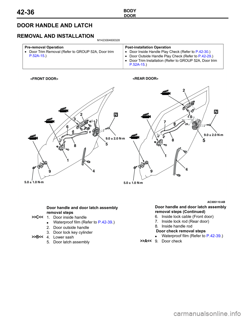
DOOR HANDLE AND LATCH
REMOVAL AND INSTALLATIONM1423004600328
Pre-removal Operation
•Door Trim Removal (Refer to GROUP 52A, Door trim
P.52A-15.)Post-installation Operation
•Door Inside Handle Play Check (Refer to P.42-30.)
•Door Outside Handle Play Check (Refer to P.42-29.)
•Door Trim Installation (Refer to GROUP 52A, Door trim
P.52A-15.)
AC305110
5
5.0 ± 1.0 N·m
1
4
9
2
AB
45 2
3
87
5.0 ± 1.0 N·m
1 6
9
NN
89.0 ± 2.0 N·m9.0 ± 2.0 N·m
Door handle and door latch assembly
removal steps
>>C<<1. Door inside handle
•Waterproof film (Refer to P.42-39.)
2. Door outside handle
3. Door lock key cylinder
>>B<<4. Lower sash
5. Door latch assembly6. Inside lock cable (Front door)
7. Inside lock rod (Rear door)
8. Inside handle rod
Door check removal steps
•Waterproof film (Refer to P.42-39.)>>A<<9. Door check Door handle and door latch assembly
removal steps (Continued)
Page 315 of 788
DOOR
BODY42-37
INSTALLATION SERVICE POINTS
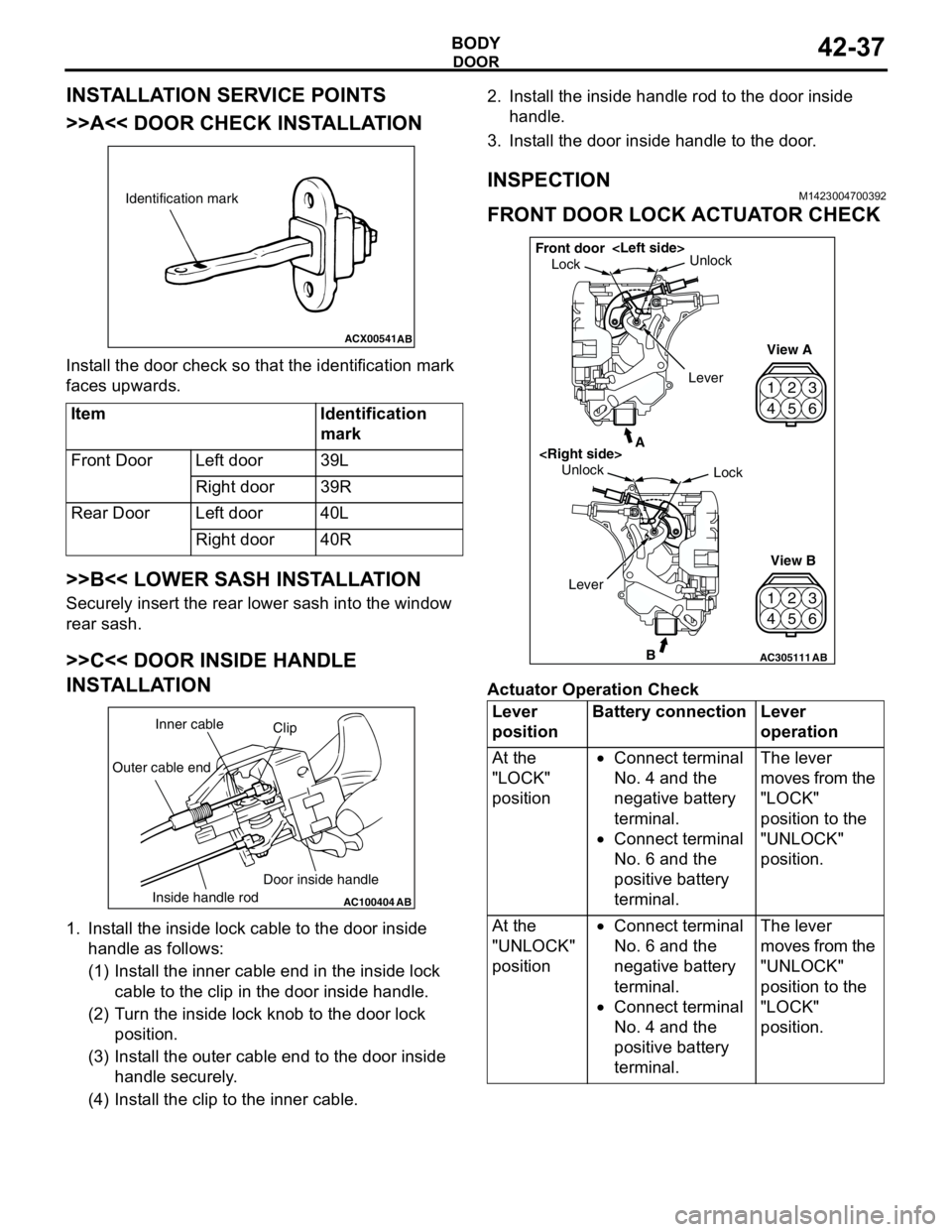
>>A<< DOOR CHECK INSTALLATION
Install the door check so that the identification mark
faces upwards.
>>B<< LOWER SASH INSTALLATION
Securely insert the rear lower sash into the window
rear sash.
>>C<< DOOR INSIDE HANDLE
INSTALLATION
1. Install the inside lock cable to the door inside
handle as follows:
(1) Install the inner cable end in the inside lock
cable to the clip in the door inside handle.
(2) Turn the inside lock knob to the door lock
position.
(3) Install the outer cable end to the door inside
handle securely.
(4) Install the clip to the inner cable.2. Install the inside handle rod to the door inside
handle.
3. Install the door inside handle to the door.
INSPECTIONM1423004700392
FRONT DOOR LOCK ACTUATOR CHECK
Actuator Operation Check Item Identification
mark
Front Door Left door 39L
Right door 39R
Rear Door Left door 40L
Right door 40R
ACX00541
Identification mark
AB
AC100404
AB
Clip Inner cable
Outer cable end
Inside handle rodDoor inside handleLever
positionBattery connection Lever
operation
At the
"LOCK"
position•Connect terminal
No. 4 and the
negative battery
terminal.
•Connect terminal
No. 6 and the
positive battery
terminal.The lever
moves from the
"LOCK"
position to the
"UNLOCK"
position.
At the
"UNLOCK"
position•Connect terminal
No. 6 and the
negative battery
terminal.
•Connect terminal
No. 4 and the
positive battery
terminal.The lever
moves from the
"UNLOCK"
position to the
"LOCK"
position.
42
53
6 1
42
53
6 1
AC305111B
A
AB
LockUnlock
View A
View B Unlock
Lock Front door
Lever
Page 316 of 788
DOOR
BODY42-38
Actuator Switch Check
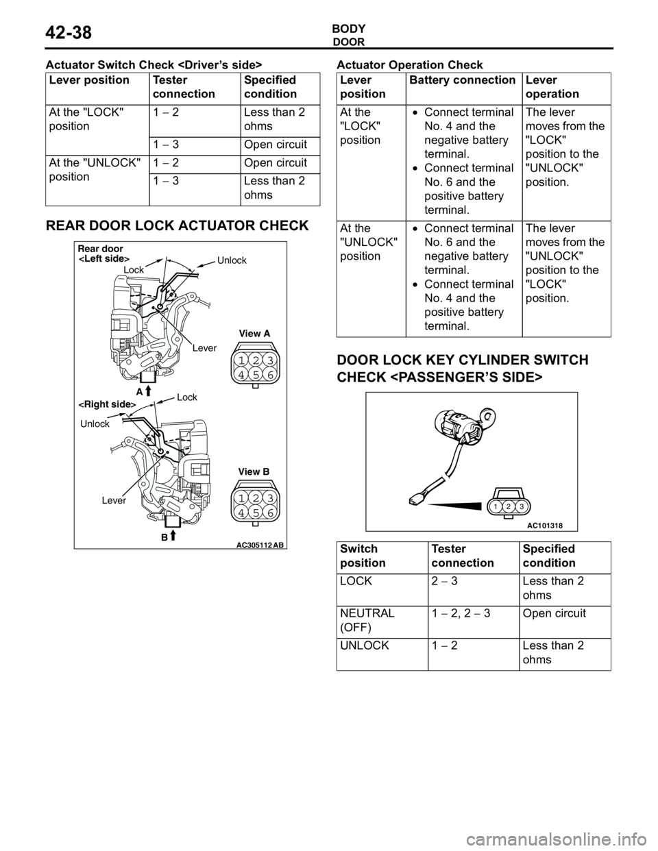
REAR DOOR LOCK ACTUATOR CHECK
Actuator Operation Check
DOOR LOCK KEY CYLINDER SWITCH
CHECK
Lever position Tester
connectionSpecified
condition
At the "LOCK"
position1 − 2 Less than 2
ohms
1 − 3 Open circuit
At the "UNLOCK"
position1 − 2 Open circuit
1 − 3 Less than 2
ohms
23
41
56
23
41
56
AC305112B
A
AB
Rear door
LockUnlock
View A
View B UnlockLock
Lever
Lever
positionBattery connection Lever
operation
At the
"LOCK"
position•Connect terminal
No. 4 and the
negative battery
terminal.
•Connect terminal
No. 6 and the
positive battery
terminal.The lever
moves from the
"LOCK"
position to the
"UNLOCK"
position.
At the
"UNLOCK"
position•Connect terminal
No. 6 and the
negative battery
terminal.
•Connect terminal
No. 4 and the
positive battery
terminal.The lever
moves from the
"UNLOCK"
position to the
"LOCK"
position.
Switch
positionTester
connectionSpecified
condition
LOCK 2 − 3 Less than 2
ohms
NEUTRAL
(OFF)1 − 2, 2 − 3 Open circuit
UNLOCK 1 − 2 Less than 2
ohms
AC101318
3 2 1
Page 317 of 788
DOOR
BODY42-39
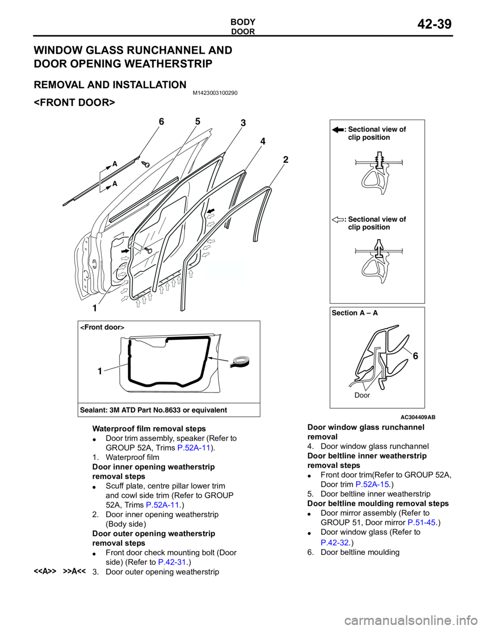
WINDOW GLASS RUNCHANNEL AND
DOOR OPENING WEATHERSTRIP
REMOVAL AND INSTALLATIONM1423003100290
AC304409AB
Section A – A
Sealant: 3M ATD Part No.8633 or equivalentDoor
: Sectional view of
clip position
: Sectional view of
clip position
6 2
1
4
365
A A
1
Waterproof film removal steps
•Door trim assembly, speaker (Refer to
GROUP 52A, Trims P.52A-11).
1. Waterproof film
Door inner opening weatherstrip
removal steps
•Scuff plate, centre pillar lower trim
and cowl side trim (Refer to GROUP
52A, Trims P.52A-11.)
2. Door inner opening weatherstrip
(Body side)
Door outer opening weatherstrip
removal steps
•Front door check mounting bolt (Door
side) (Refer to P.42-31.)
<> >>A<<3. Door outer opening weatherstripDoor window glass runchannel
removal
4. Door window glass runchannel
Door beltline inner weatherstrip
removal steps
•Front door trim(Refer to GROUP 52A,
Door trim P.52A-15.)
5. Door beltline inner weatherstrip
Door beltline moulding removal steps
•Door mirror assembly (Refer to
GROUP 51, Door mirror P.51-45.)
•Door window glass (Refer to
P.42-32.)
6. Door beltline moulding
Page 318 of 788
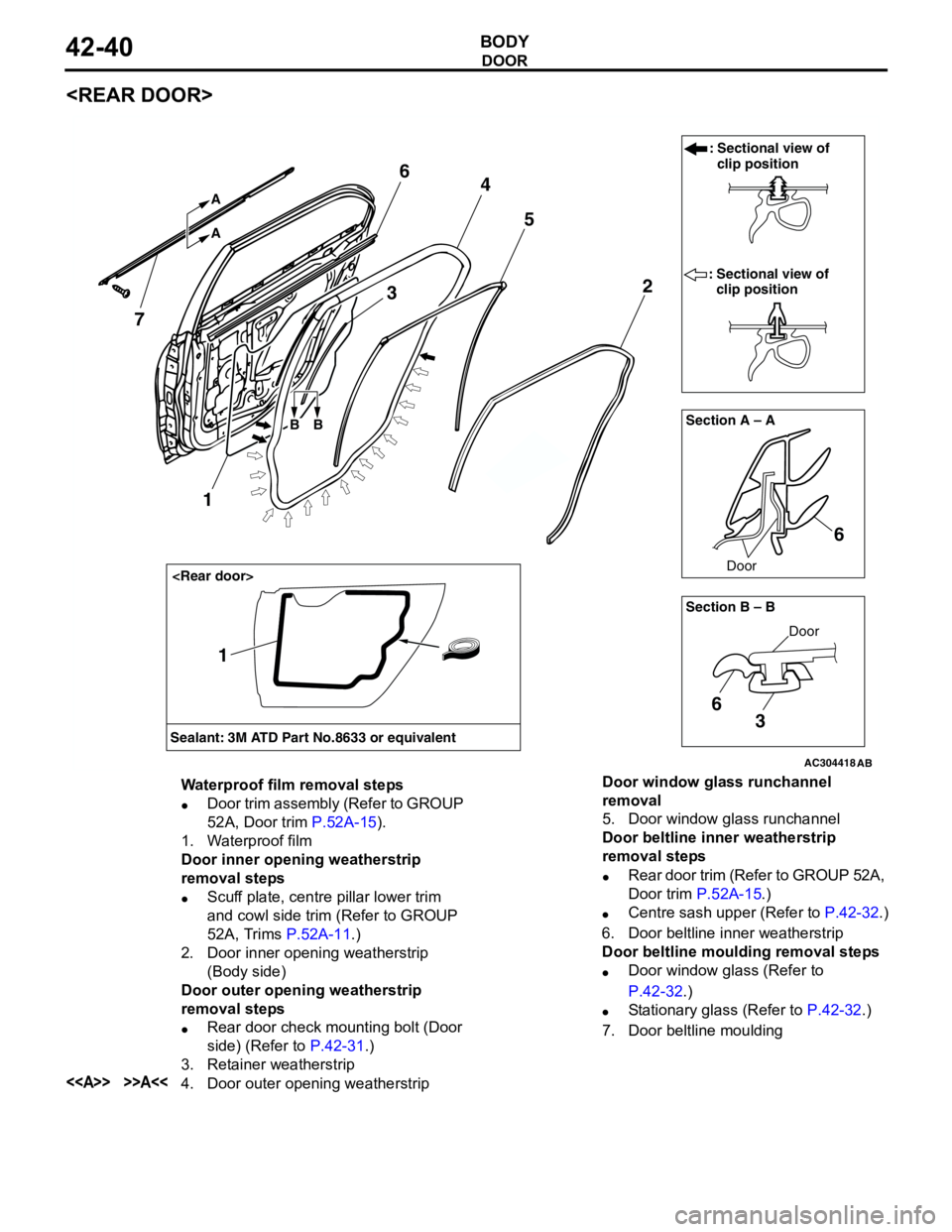
DOOR
BODY42-40
AC304418AB
Section A – A
Door
: Sectional view of
clip position
: Sectional view of
clip position
6 2 4
5
7
A A
3
Section B – B
Door
6
3
6
BB
Sealant: 3M ATD Part No.8633 or equivalent
1
1
Waterproof film removal steps
•Door trim assembly (Refer to GROUP
52A, Door trim P.52A-15).
1. Waterproof film
Door inner opening weatherstrip
removal steps
•Scuff plate, centre pillar lower trim
and cowl side trim (Refer to GROUP
52A, Trims P.52A-11.)
2. Door inner opening weatherstrip
(Body side)
Door outer opening weatherstrip
removal steps
•Rear door check mounting bolt (Door
side) (Refer to P.42-31.)
3. Retainer weatherstrip
<> >>A<<4. Door outer opening weatherstripDoor window glass runchannel
removal
5. Door window glass runchannel
Door beltline inner weatherstrip
removal steps
•Rear door trim (Refer to GROUP 52A,
Door trim P.52A-15.)
•Centre sash upper (Refer to P.42-32.)
6. Door beltline inner weatherstrip
Door beltline moulding removal steps
•Door window glass (Refer to
P.42-32.)
•Stationary glass (Refer to P.42-32.)
7. Door beltline moulding
Page 319 of 788
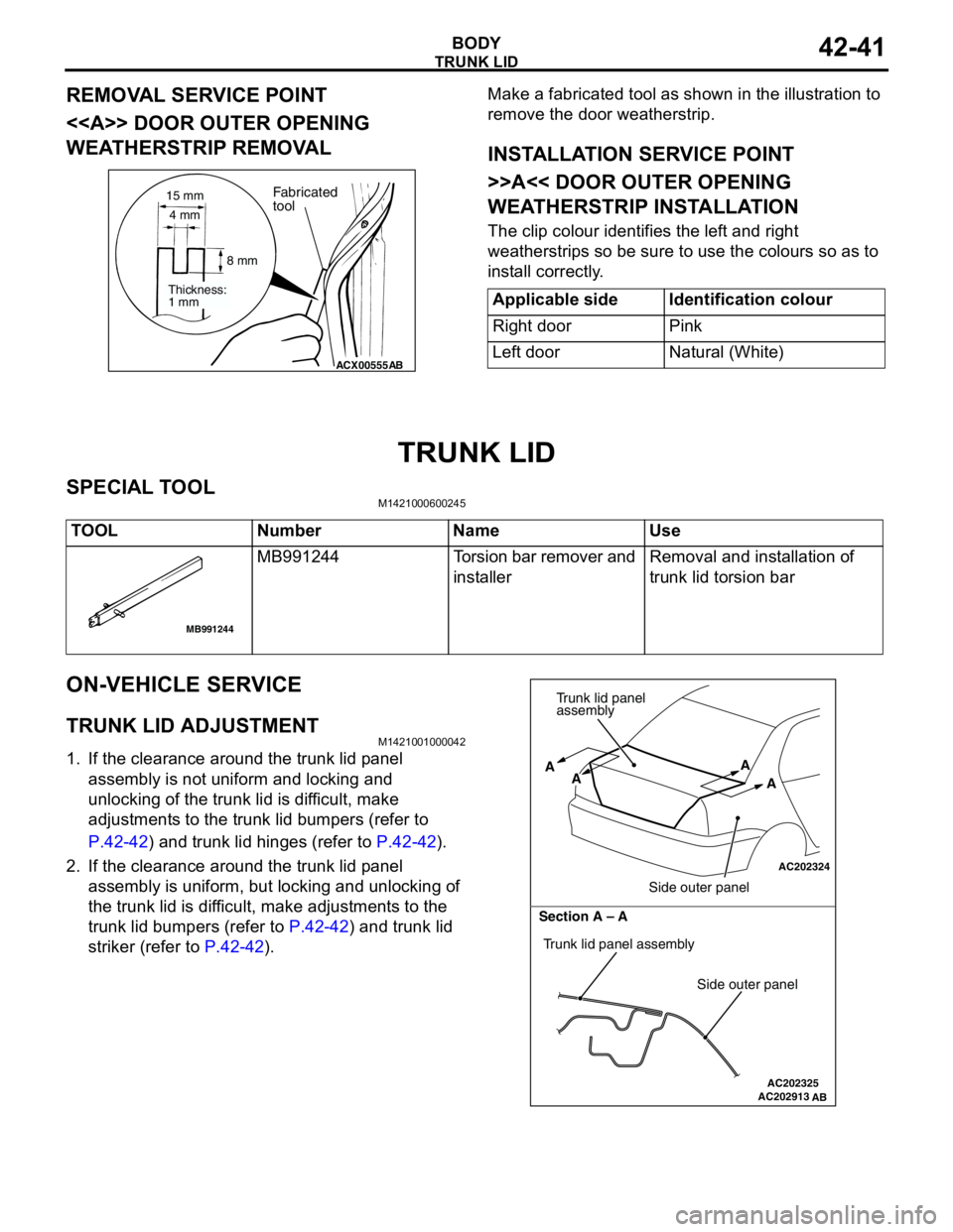
Page 320 of 788
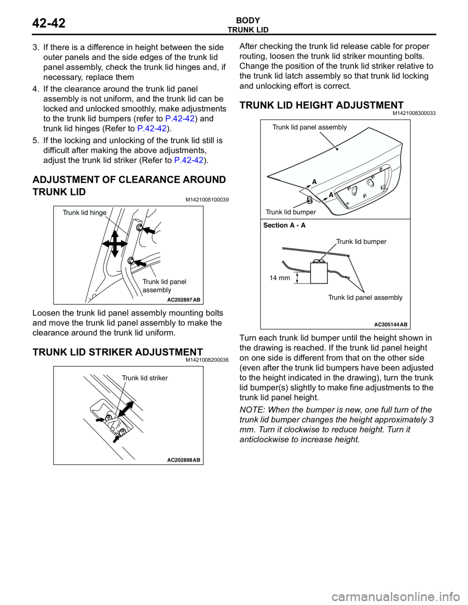
TRUNK LID
BODY42-42
3. If there is a difference in height between the side
outer panels and the side edges of the trunk lid
panel assembly, check the trunk lid hinges and, if
necessary, replace them
4. If the clearance around the trunk lid panel
assembly is not uniform, and the trunk lid can be
locked and unlocked smoothly, make adjustments
to the trunk lid bumpers (refer to P.42-42) and
trunk lid hinges (Refer to P.42-42).
5. If the locking and unlocking of the trunk lid still is
difficult after making the above adjustments,
adjust the trunk lid striker (Refer to P.42-42).
ADJUSTMENT OF CLEARANCE AROUND
TRUNK LID
M1421008100039
Loosen the trunk lid panel assembly mounting bolts
and move the trunk lid panel assembly to make the
clearance around the trunk lid uniform.
TRUNK LID STRIKER ADJUSTMENTM1421008200036
After checking the trunk lid release cable for proper
routing, loosen the trunk lid striker mounting bolts.
Change the position of the trunk lid striker relative to
the trunk lid latch assembly so that trunk lid locking
and unlocking effort is correct.
TRUNK LID HEIGHT ADJUSTMENTM1421008300033
Turn each trunk lid bumper until the height shown in
the drawing is reached. If the trunk lid panel height
on one side is different from that on the other side
(even after the trunk lid bumpers have been adjusted
to the height indicated in the drawing), turn the trunk
lid bumper(s) slightly to make fine adjustments to the
trunk lid panel height.
NOTE: When the bumper is new, one full turn of the
trunk lid bumper changes the height approximately 3
mm. Turn it clockwise to reduce height. Turn it
anticlockwise to increase height.
AC202897
Trunk lid panel
assembly
Trunk lid hinge
AB
AC202898
Trunk lid striker
AB
AC305144
Section A - A
Trunk lid bumper
Trunk lid panel assembly A
A
Trunk lid bumperTrunk lid panel assembly
AB
14 mm
Page 321 of 788
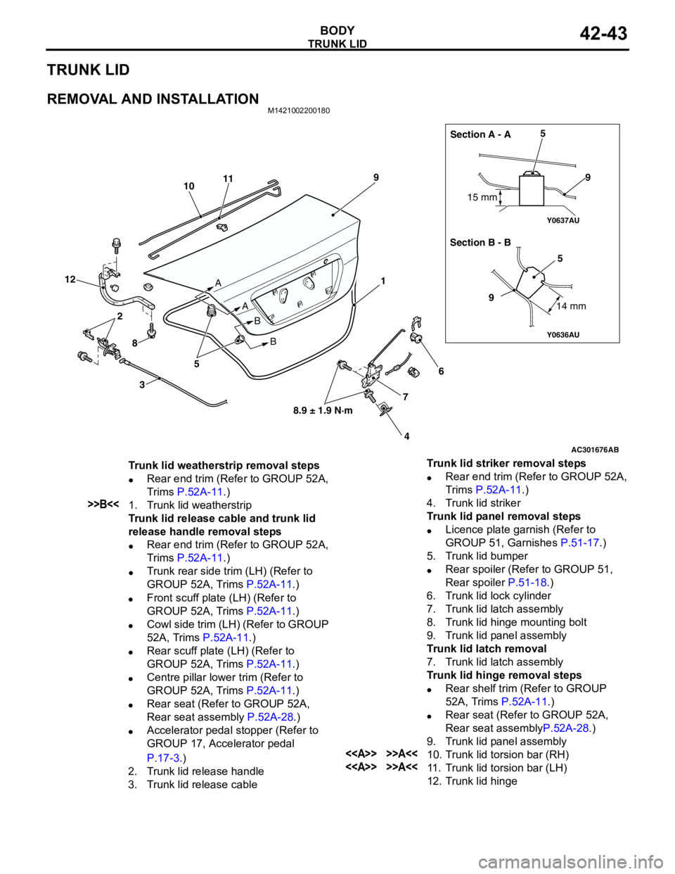
TRUNK LID
BODY42-43
TRUNK LID
REMOVAL AND INSTALLATIONM1421002200180
AC301676
Y0636AU
Y0637AU
AB
1
2
3
45
5
6
7 89
10
99
11
12
8.9 ± 1.9 N·m A
A
B
B15 mm
14 mm
5Section A - A
Section B - B
Trunk lid weatherstrip removal steps
•Rear end trim (Refer to GROUP 52A,
Trims P.52A-11.)
>>B<<1. Trunk lid weatherstrip
Trunk lid release cable and trunk lid
release handle removal steps
•Rear end trim (Refer to GROUP 52A,
Trims P.52A-11.)
•Trunk rear side trim (LH) (Refer to
GROUP 52A, Trims P.52A-11.)
•Front scuff plate (LH) (Refer to
GROUP 52A, Trims P.52A-11.)
•Cowl side trim (LH) (Refer to GROUP
52A, Trims P.52A-11.)
•Rear scuff plate (LH) (Refer to
GROUP 52A, Trims P.52A-11.)
•Centre pillar lower trim (Refer to
GROUP 52A, Trims P.52A-11.)
•Rear seat (Refer to GROUP 52A,
Rear seat assembly P.52A-28.)
•Accelerator pedal stopper (Refer to
GROUP 17, Accelerator pedal
P.17-3.)
2. Trunk lid release handle
3. Trunk lid release cableTrunk lid striker removal steps
•Rear end trim (Refer to GROUP 52A,
Trims P.52A-11.)
4. Trunk lid striker
Trunk lid panel removal steps
•Licence plate garnish (Refer to
GROUP 51, Garnishes P.51-17.)
5. Trunk lid bumper
•Rear spoiler (Refer to GROUP 51,
Rear spoiler P.51-18.)
6. Trunk lid lock cylinder
7. Trunk lid latch assembly
8. Trunk lid hinge mounting bolt
9. Trunk lid panel assembly
Trunk lid latch removal
7. Trunk lid latch assembly
Trunk lid hinge removal steps
•Rear shelf trim (Refer to GROUP
52A, Trims P.52A-11.)
•Rear seat (Refer to GROUP 52A,
Rear seat assemblyP.52A-28.)
9. Trunk lid panel assembly
<> >>A<<10. Trunk lid torsion bar (RH)
<> >>A<<11. Trunk lid torsion bar (LH)
12. Trunk lid hinge
Page 326 of 788
TA I L G AT E
BODY42-48
TAILGATE
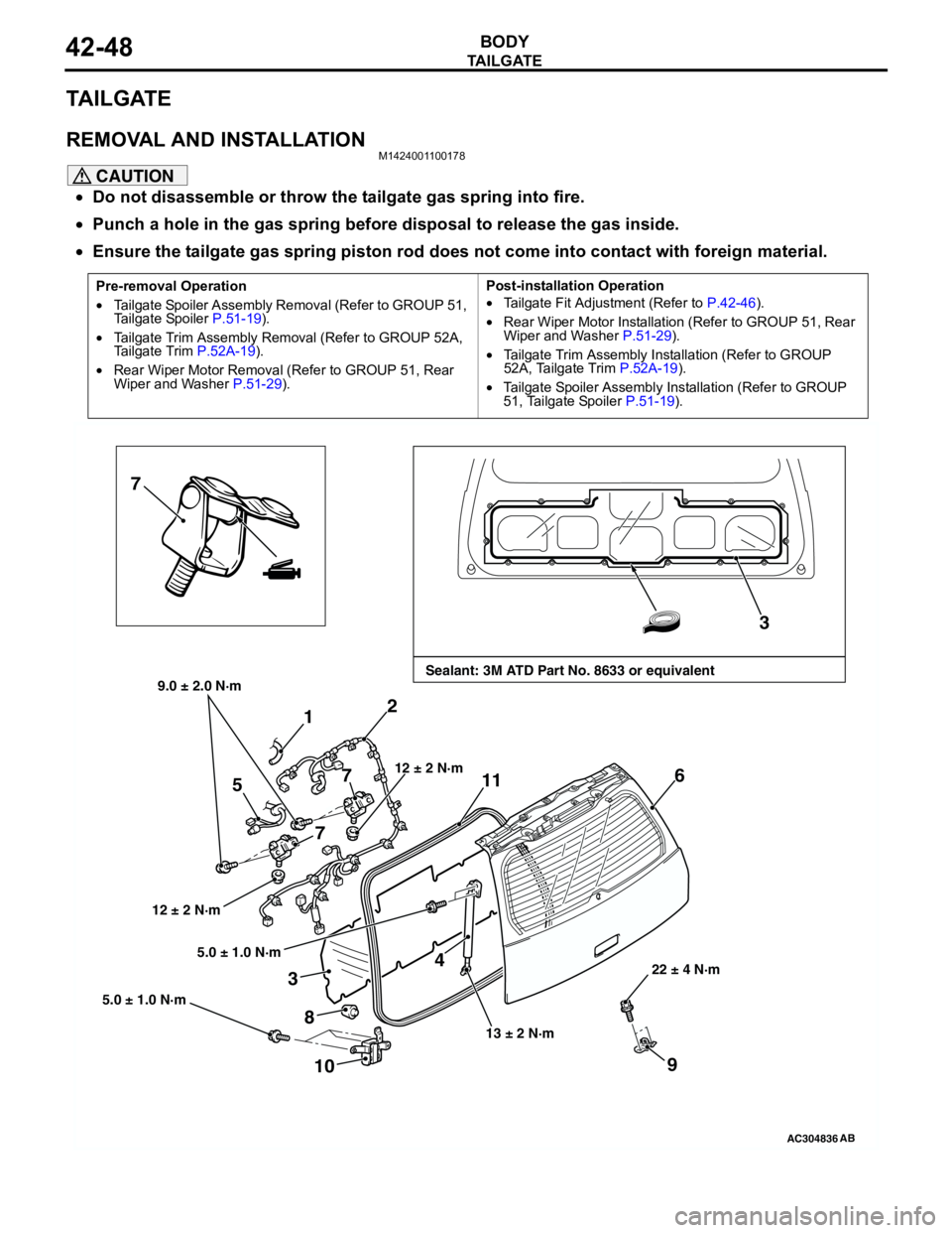
REMOVAL AND INSTALLATIONM1424001100178
CAUTION
•Do not disassemble or throw the tailgate gas spring into fire.
•Punch a hole in the gas spring before disposal to release the gas inside.
•Ensure the tailgate gas spring piston rod does not come into contact with foreign material.
Pre-removal Operation
•Tailgate Spoiler Assembly Removal (Refer to GROUP 51,
Tailgate Spoiler P.51-19).
•Tailgate Trim Assembly Removal (Refer to GROUP 52A,
Tailgate Trim P.52A-19).
•Rear Wiper Motor Removal (Refer to GROUP 51, Rear
Wiper and Washer P.51-29).Post-installation Operation
•Tailgate Fit Adjustment (Refer to P.42-46).
•Rear Wiper Motor Installation (Refer to GROUP 51, Rear
Wiper and Washer P.51-29).
•Tailgate Trim Assembly Installation (Refer to GROUP
52A, Tailgate Trim P.52A-19).
•Tailgate Spoiler Assembly Installation (Refer to GROUP
51, Tailgate Spoiler P.51-19).
AC304836
7
3
4 1
6
8
12 ± 2 N·m
13 ± 2 N·m22 ± 4 N·m
AB
Sealant: 3M ATD Part No. 8633 or equivalent9.0 ± 2.0 N·m
2
712 ± 2 N·m
5
7
9
5.0 ± 1.0 N·m
5.0 ± 1.0 N·m
3
11
10
Page 331 of 788
KEYLESS ENTRY SYSTEM
BODY42-53
TROUBLESHOOTINGM1428000700287
The keyless entry system is controlled by the Smart
Wiring System (SWS). For troubleshooting, refer to
GROUP 54B, Troubleshooting P.54B-17 or GROUP
54C, Troubleshooting P.54C-4.
ON-VEHICLE SERVICE
KEYLESS ENTRY SYSTEM CHECKM1428001400096
Check the system as described below. If the system
does not work, carry out troubleshooting. Refer to
GROUP 54B, Troubleshooting P.54B-17, refer to
GROUP 54C, Troubleshooting P.54C-4.
•Operate the transmitter to check that the doors
and tailgate can be locked and unlocked.
•Operate the transmitter to check that the
answerback function works in response to door
and tailgate
NOTE: The adjustment function allows you to
change the answerback setting as follows. Prior
to that check, confirm which setting is activated.
.
•The hazard warning lamps flash twice when
locked and once when unlocked. The room
lamp flashes twice when locked and
illuminates for 15 seconds when unlocked.
•The hazard warning lamps do not flash when
locked and flash once when unlocked. The
room lamp flashes twice when locked and
illuminates for 15 seconds when unlocked.
•The hazard warning lamps flash twice when
locked and do not flash when unlocked. The
room lamp flashes twice when locked and
illuminates for 15 seconds when unlocked.
•The hazard warning lamps do not flash when
both locked and unlocked. The room lamp
flashes twice when locked and illuminates for
15 seconds when unlocked.
KEYLESS ENTRY SYSTEM TIMER LOCK
FUNCTION INSPECTION
M1428004000138
Push the transmitter unlock button and check to see
that the doors and tailgate
seconds. If it doesn't, then execute troubleshooting
remedies. Refer to GROUP 54B, Troubleshooting
P.54B-17, refer to GROUP 54C, Troubleshooting
P.54C-4.
ENABLING/DISABLING THE
ANSWERBACK FUNCTION
M1428003200214
If the keyless entry system locks or unlocks the
doors, the room lamp flashes or illuminates, the
hazard warning lamp flashes (hazard answerback
function). The hazard answerback function can be
enabled or disabled according to the following
procedure:
ENABLING/DISABLING THE HAZARD
ANSWERBACK FUNCTION
The hazard answerback function can be enabled or
disabled by one of the two following procedures.
1. Enter the hazard answerback customize mode by
performing one of the following steps. If the
ETACS-ECU enters the customize mode, its
buzzer will sound once.
(1) Turn the ignition switch to “LOCK”(OFF)
position.
(2) Turn off the hazard warning lamp switch.
CAUTION
Before connecting or disconnecting the earth,
turn the ignition switch to the "LOCK" (OFF)
position.
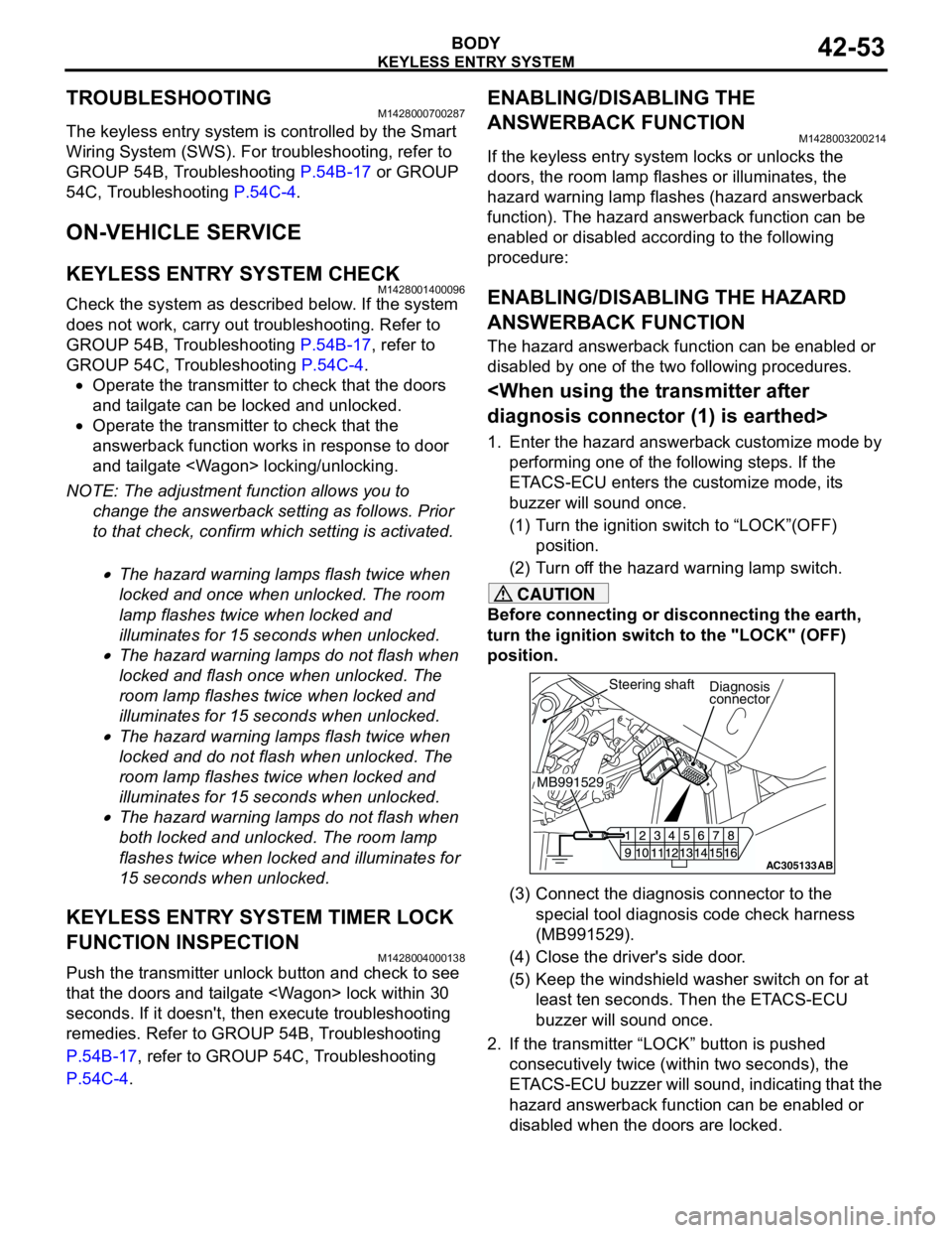
(3) Connect the diagnosis connector to the
special tool diagnosis code check harness
(MB991529).
(4) Close the driver's side door.
(5) Keep the windshield washer switch on for at
least ten seconds. Then the ETACS-ECU
buzzer will sound once.
2. If the transmitter “LOCK” button is pushed
consecutively twice (within two seconds), the
ETACS-ECU buzzer will sound, indicating that the
hazard answerback function can be enabled or
disabled when the doors are locked.
AC305133AB
Diagnosis
connector
MB991529Steering shaft