Side MITSUBISHI LANCER 2005 Workshop Manual
[x] Cancel search | Manufacturer: MITSUBISHI, Model Year: 2005, Model line: LANCER, Model: MITSUBISHI LANCER 2005Pages: 788, PDF Size: 45.98 MB
Page 332 of 788
KEYLESS ENTRY SYSTEM
BODY42-54
•Enable the hazard answerback function
when the doors are locked: The
ETACS-ECU buzzer will sound once.
•Disable the hazard answerback function
when the doors are locked: The
ETACS-ECU buzzer will sound twice.
3. If the transmitter “UNLOCK” button is pushed
consecutively twice (within two seconds), the
ETACS-ECU buzzer will sound, indicating that the
hazard answerback function can be enabled or
disabled when the doors are unlocked.
•Enable the hazard answerback function
when the doors are unlocked: The
ETACS-ECU buzzer will sound once.
•Disable the hazard answerback function
when the doors are unlocked: The
ETACS-ECU buzzer will sound twice.
4. Exit the hazard answerback customize mode by
observing one of the following steps.
(1) Disconnect diagnosis connector terminal (1)
form the earth.
(2) Turn the ignition switch to position other then
“LOCK”(OFF), or remove the ignition key.
(3) Open the driver's side door.
(4) Any other warning buzzer output occurs.
NOTE: If any operation is not done for at least three
minutes after the ETACS-ECU has entered the
customize mode, the hazard answerback customize
mode will be canceled automatically.
connector>
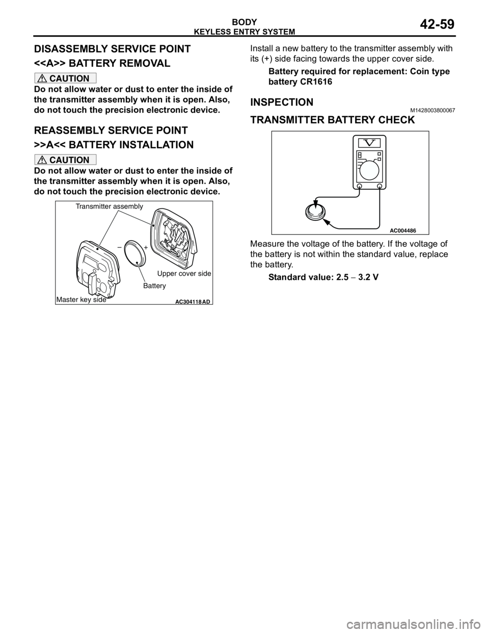
1. Enter the hazard answerback customize mode by
performing one of the following steps. If the
ETACS-ECU enters the customize mode, its
buzzer will sound once.
(1) Turn the ignition switch to “LOCK”(OFF)
position.
(2) Turn off the hazard warning lamp switch.
CAUTION
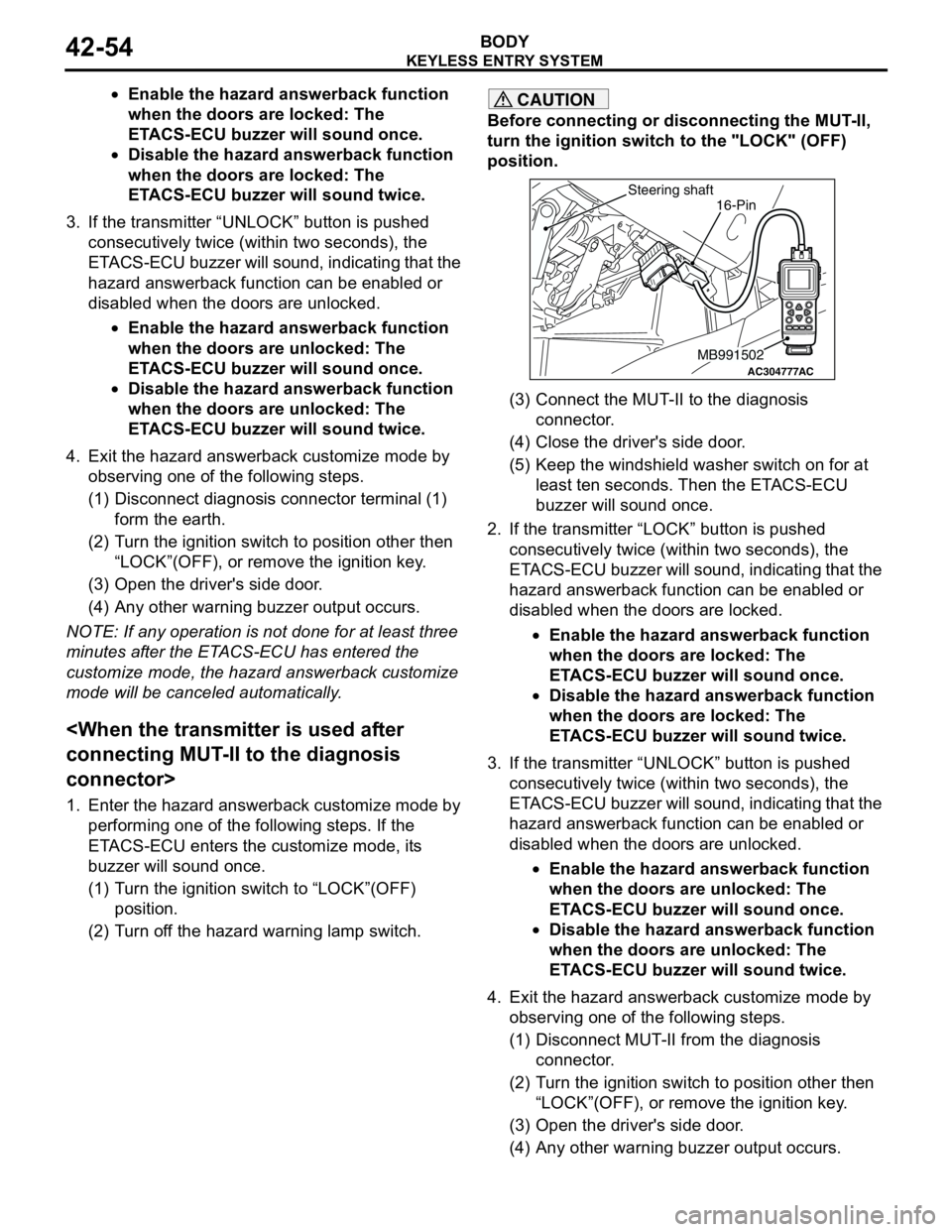
Before connecting or disconnecting the MUT-II,
turn the ignition switch to the "LOCK" (OFF)
position.
(3) Connect the MUT-II to the diagnosis
connector.
(4) Close the driver's side door.
(5) Keep the windshield washer switch on for at
least ten seconds. Then the ETACS-ECU
buzzer will sound once.
2. If the transmitter “LOCK” button is pushed
consecutively twice (within two seconds), the
ETACS-ECU buzzer will sound, indicating that the
hazard answerback function can be enabled or
disabled when the doors are locked.
•Enable the hazard answerback function
when the doors are locked: The
ETACS-ECU buzzer will sound once.
•Disable the hazard answerback function
when the doors are locked: The
ETACS-ECU buzzer will sound twice.
3. If the transmitter “UNLOCK” button is pushed
consecutively twice (within two seconds), the
ETACS-ECU buzzer will sound, indicating that the
hazard answerback function can be enabled or
disabled when the doors are unlocked.
•Enable the hazard answerback function
when the doors are unlocked: The
ETACS-ECU buzzer will sound once.
•Disable the hazard answerback function
when the doors are unlocked: The
ETACS-ECU buzzer will sound twice.
4. Exit the hazard answerback customize mode by
observing one of the following steps.
(1) Disconnect MUT-II from the diagnosis
connector.
(2) Turn the ignition switch to position other then
“LOCK”(OFF), or remove the ignition key.
(3) Open the driver's side door.
(4) Any other warning buzzer output occurs.
AC304777
Steering shaft
ACMB991502
16-Pin
Page 333 of 788
KEYLESS ENTRY SYSTEM
BODY42-55
NOTE: If any operation is not done for at least three
minutes after the ETACS-ECU has entered the
customize mode, the hazard answerback customize
mode will be canceled automatically.
(MB991824) to the diagnosis connector>
1. Enter the hazard answerback customize mode by
performing one of the following steps. If the
ETACS-ECU enters the customize mode, its
buzzer will sound once.
(1) Turn the ignition switch to “LOCK”(OFF)
position.
(2) Turn off the hazard warning lamp switch.
CAUTION
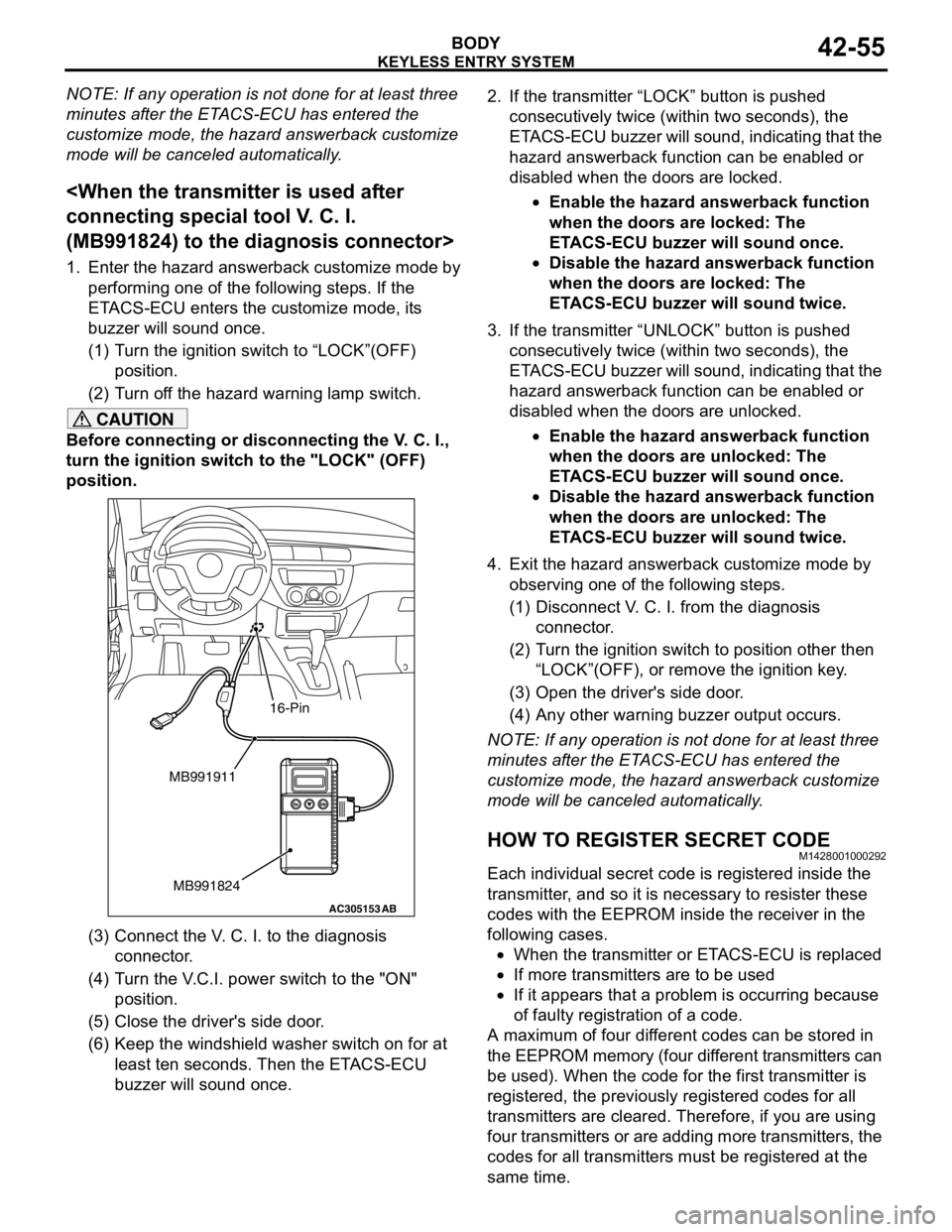
Before connecting or disconnecting the V. C. I.,
turn the ignition switch to the "LOCK" (OFF)
position.
(3) Connect the V. C. I. to the diagnosis
connector.
(4) Turn the V.C.I. power switch to the "ON"
position.
(5) Close the driver's side door.
(6) Keep the windshield washer switch on for at
least ten seconds. Then the ETACS-ECU
buzzer will sound once.2. If the transmitter “LOCK” button is pushed
consecutively twice (within two seconds), the
ETACS-ECU buzzer will sound, indicating that the
hazard answerback function can be enabled or
disabled when the doors are locked.
•Enable the hazard answerback function
when the doors are locked: The
ETACS-ECU buzzer will sound once.
•Disable the hazard answerback function
when the doors are locked: The
ETACS-ECU buzzer will sound twice.
3. If the transmitter “UNLOCK” button is pushed
consecutively twice (within two seconds), the
ETACS-ECU buzzer will sound, indicating that the
hazard answerback function can be enabled or
disabled when the doors are unlocked.
•Enable the hazard answerback function
when the doors are unlocked: The
ETACS-ECU buzzer will sound once.
•Disable the hazard answerback function
when the doors are unlocked: The
ETACS-ECU buzzer will sound twice.
4. Exit the hazard answerback customize mode by
observing one of the following steps.
(1) Disconnect V. C. I. from the diagnosis
connector.
(2) Turn the ignition switch to position other then
“LOCK”(OFF), or remove the ignition key.
(3) Open the driver's side door.
(4) Any other warning buzzer output occurs.
NOTE: If any operation is not done for at least three
minutes after the ETACS-ECU has entered the
customize mode, the hazard answerback customize
mode will be canceled automatically.
HOW TO REGISTER SECRET CODEM1428001000292
Each individual secret code is registered inside the
transmitter, and so it is necessary to resister these
codes with the EEPROM inside the receiver in the
following cases.
•When the transmitter or ETACS-ECU is replaced
•If more transmitters are to be used
•If it appears that a problem is occurring because
of faulty registration of a code.
A maximum of four different codes can be stored in
the EEPROM memory (four different transmitters can
be used). When the code for the first transmitter is
registered, the previously registered codes for all
transmitters are cleared. Therefore, if you are using
four transmitters or are adding more transmitters, the
codes for all transmitters must be registered at the
same time.
AC305153AB
MB991911
MB991824
16-Pin
Page 337 of 788
Page 339 of 788
51-1
GROUP 51
EXTERIOR
CONTENTS
FRONT BUMPER ASSEMBLY . . . . .51-2
ADHESIVE . . . . . . . . . . . . . . . . . . . . . . . . . 51-2
FRONT BUMPER ASSEMBLY . . . . . . . . . . 51-2
REMOVAL AND INSTALLATION . . . . . . . . 51-2
DISASSEMBLY AND REASSEMBLY . . . . . 51-3
REAR BUMPER ASSEMBLY . . . . . .51-5
REMOVAL AND INSTALLATION . . . . . . . . 51-5
DISASSEMBLY AND REASSEMBLY . . . . . 51-7
MOULDINGS . . . . . . . . . . . . . . . . . . .51-9
SPECIAL TOOL . . . . . . . . . . . . . . . . . . . . . 51-9
ADHESIVE . . . . . . . . . . . . . . . . . . . . . . . . . 51-9
MOULDINGS . . . . . . . . . . . . . . . . . . . . . . . 51-10
REMOVAL AND INSTALLATION . . . . . . . . 51-10
SIDE AIR DAM . . . . . . . . . . . . . . . . . .51-15
ADHESIVE . . . . . . . . . . . . . . . . . . . . . . . . . 51-15
SIDE AIR DAM . . . . . . . . . . . . . . . . . . . . . . 51-15
REMOVAL AND INSTALLATION . . . . . . . . 51-15
GARNISHES . . . . . . . . . . . . . . . . . . .51-17
REMOVAL AND INSTALLATION . . . . . . . . 51-17
REAR SPOILER . . . . . . . . . . . . . . . . .51-18
REMOVAL AND INSTALLATION . . . . . . . . 51-18
TAILGATE SPOILER . . . . . . . . . . . . .51-19
REMOVAL AND INSTALLATION . . . . . . . . 51-19
ROOF RAIL . . . . . . . . . . . . . . . . . . . .51-20
REMOVAL AND INSTALLATION . . . . . . . . 51-20
WINDSHIELD WIPER AND WASHER51-21
GENERAL INFORMATION . . . . . . . . . . . . . 51-21
SERVICE SPECIFICATION . . . . . . . . . . . . 51-22TROUBLESHOOTING . . . . . . . . . . . . . . . . 51-22
ON-VEHICLE SERVICE . . . . . . . . . . . . . . . 51-22
WINDSHIELD WIPER AND WASHER . . . . 51-23
REMOVAL AND INSTALLATION . . . . . . . . 51-23
INSPECTION . . . . . . . . . . . . . . . . . . . . . . . . 51-25
REAR WIPER AND WASHER . . . . . .51-28
GENERAL INFORMATION . . . . . . . . . . . . . 51-28
SERVICE SPECIFICATION . . . . . . . . . . . . 51-28
TROUBLESHOOTING . . . . . . . . . . . . . . . . 51-28
ON-VEHICLE SERVICE . . . . . . . . . . . . . . . 51-28
REAR WIPER AND WASHER . . . . . . . . . . 51-29
REMOVAL AND INSTALLATION . . . . . . . . 51-29
INSPECTION . . . . . . . . . . . . . . . . . . . . . . . . 51-30
HEADLAMP WASHER . . . . . . . . . . . .51-32
TROUBLESHOOTING . . . . . . . . . . . . . . . . 51-32
HEADLAMP WASHER . . . . . . . . . . . . . . . . 51-32
REMOVAL AND INSTALLATION . . . . . . . . 51-32
INSPECTION . . . . . . . . . . . . . . . . . . . . . . . . 51-33
MARK . . . . . . . . . . . . . . . . . . . . . . . . .51-34
REMOVAL AND INSTALLATION . . . . . . . . 51-34
DOOR MIRROR . . . . . . . . . . . . . . . . .51-36
GENERAL INFORMATION . . . . . . . . . . . . . 51-36
SERVICE SPECIFICATION . . . . . . . . . . . . 51-36
SPECIAL TOOL. . . . . . . . . . . . . . . . . . . . . . 51-36
TROUBLESHOOTING . . . . . . . . . . . . . . . . 51-36
DIAGNOSIS TROUBLESHOOTING
FLOW . . . . . . . . . . . . . . . . . . . . . . . . . . . . . 51-36
TROUBLE SYMPTOM CHART . . . . . . . . . . 51-36
SYMPTOM PROCEDURES . . . . . . . . . . . . 51-37
DOOR MIRROR . . . . . . . . . . . . . . . . . . . . . 51-45
REMOVAL AND INSTALLATION . . . . . . . . 51-45
INSPECTION . . . . . . . . . . . . . . . . . . . . . . . . 51-47
Page 340 of 788
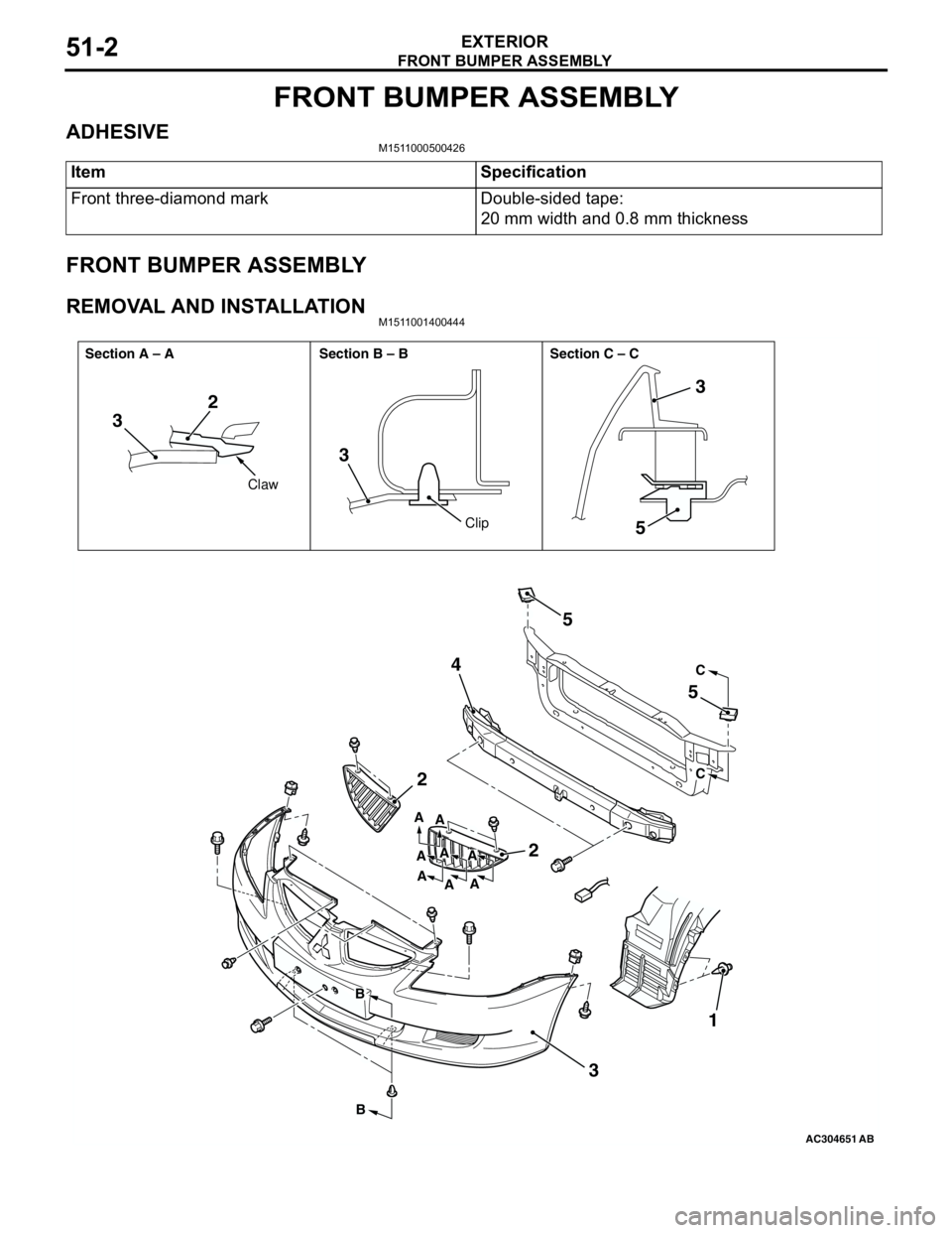
FRONT BUMPER ASSEMBLY
EXTERIOR51-2
FRONT BUMPER ASSEMBLY
ADHESIVEM1511000500426
FRONT BUMPER ASSEMBLY
REMOVAL AND INSTALLATIONM1511001400444
Item Specification
Front three-diamond mark Double-sided tape:
20 mm width and 0.8 mm thickness
AC304651AB
32
3
5
2
2 45
5
31
3
C
C
B
BA
A
A A A
A
AA
Claw
Clip Section A – A Section B – B Section C – C
Page 341 of 788
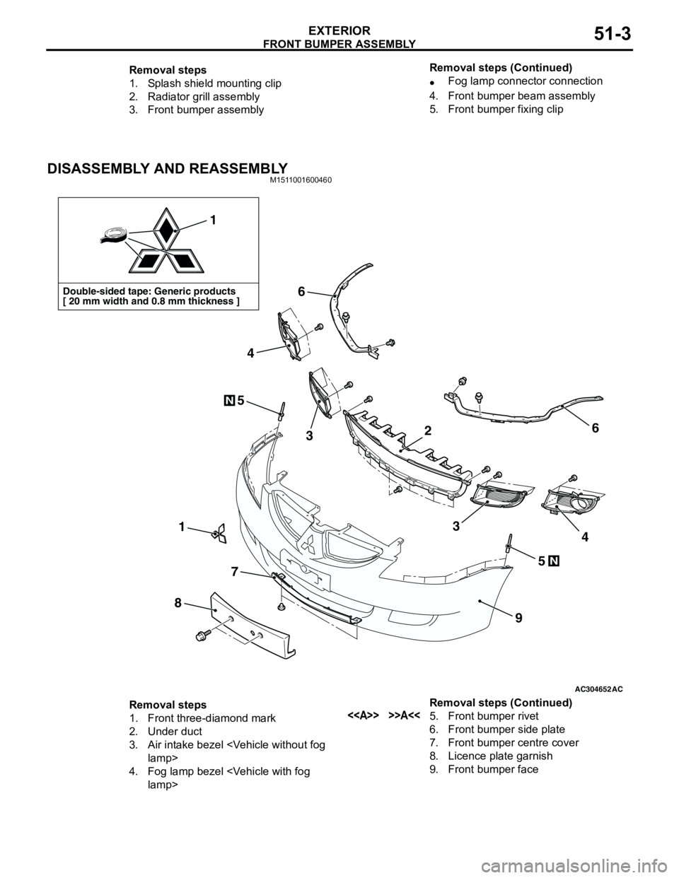
FRONT BUMPER ASSEMBLY
EXTERIOR51-3
DISASSEMBLY AND REASSEMBLYM1511001600460
Removal steps
1. Splash shield mounting clip
2. Radiator grill assembly
3. Front bumper assembly•Fog lamp connector connection
4. Front bumper beam assembly
5. Front bumper fixing clip Removal steps (Continued)
AC304652AC
Double-sided tape: Generic products
[ 20 mm width and 0.8 mm thickness ]
1
1
8
7
9
6
6
5
5
3
4
34
N
N
2
Removal steps
1. Front three-diamond mark
2. Under duct
3. Air intake bezel
4. Fog lamp bezel
6. Front bumper side plate
7. Front bumper centre cover
8. Licence plate garnish
9. Front bumper face Removal steps (Continued)
Page 342 of 788
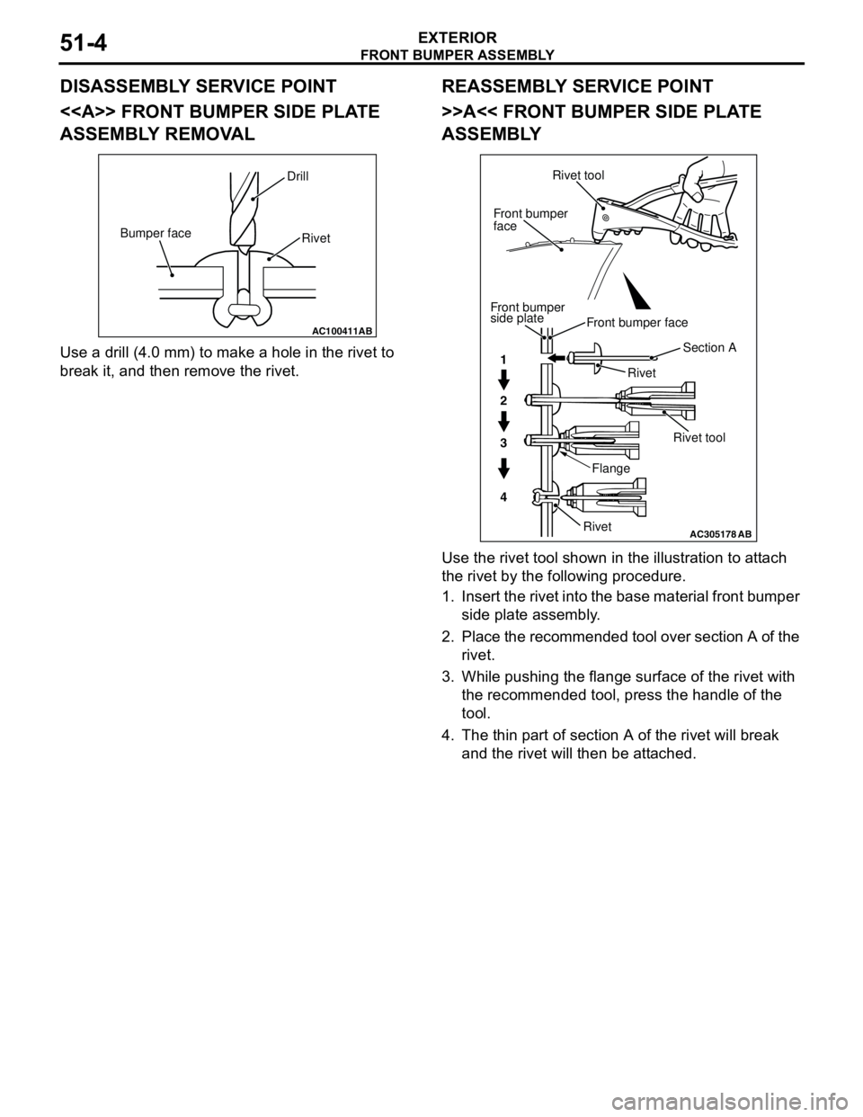
Page 345 of 788
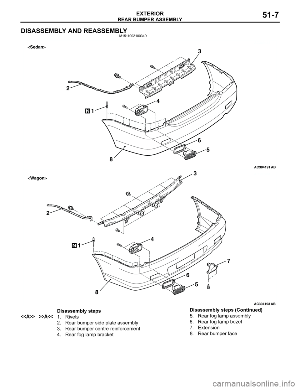
REAR BUMPER ASSEMBLY
EXTERIOR51-7
DISASSEMBLY AND REASSEMBLYM1511002100349
AC300414
AC304191
1
2
8
N
3
4
5
6
AB
AC300200
AC304193
1
2
8
N
3
4
5
7
6
AB
Disassembly steps
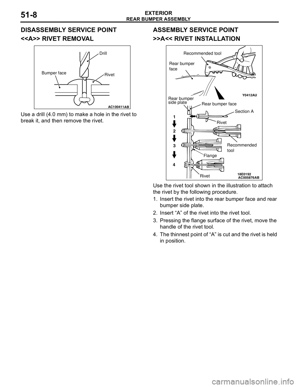
<> >>A<<1. Rivets
2. Rear bumper side plate assembly
3. Rear bumper centre reinforcement
4. Rear fog lamp bracket5. Rear fog lamp assembly
6. Rear fog lamp bezel
7. Extension
8. Rear bumper face Disassembly steps (Continued)
Page 346 of 788
Page 347 of 788
MOULDINGS
EXTERIOR51-9
MOULDINGS
SPECIAL TOOLM1511000601136
ADHESIVEM1511000500749
Tool Number Name Application
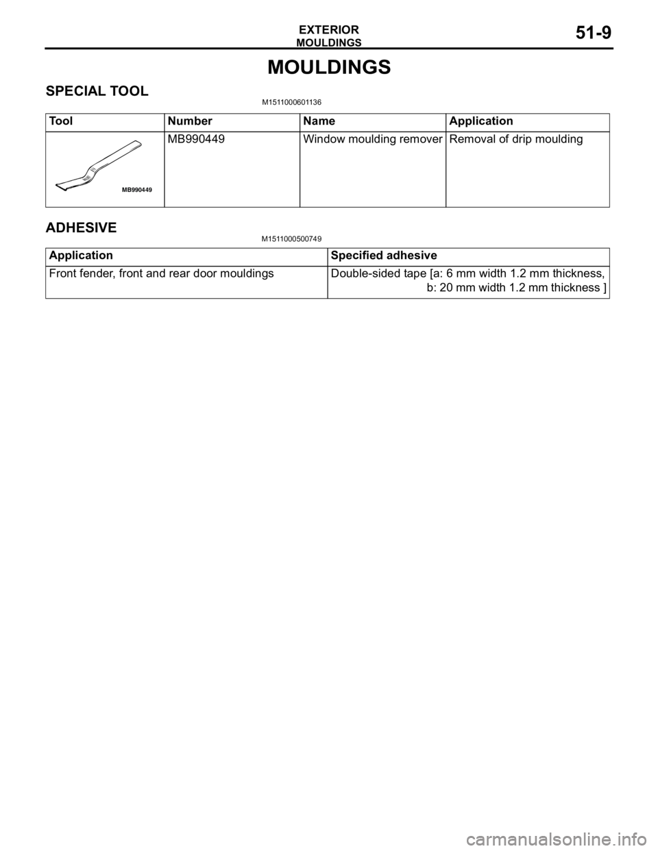
MB990449 Window moulding remover Removal of drip moulding
MB990449
Application Specified adhesive
Front fender, front and rear door mouldings Double-sided tape [a: 6 mm width 1.2 mm thickness,
b: 20 mm width 1.2 mm thickness ]