Side MITSUBISHI LANCER 2005 Workshop Manual
[x] Cancel search | Manufacturer: MITSUBISHI, Model Year: 2005, Model line: LANCER, Model: MITSUBISHI LANCER 2005Pages: 788, PDF Size: 45.98 MB
Page 351 of 788
MOULDINGS
EXTERIOR51-13
AC401196 AC400117
AC400128
Section A – A Section B – B Section C – C
AB
A
AB
BC
C
2
1
3
ClipClip
AC400840AD
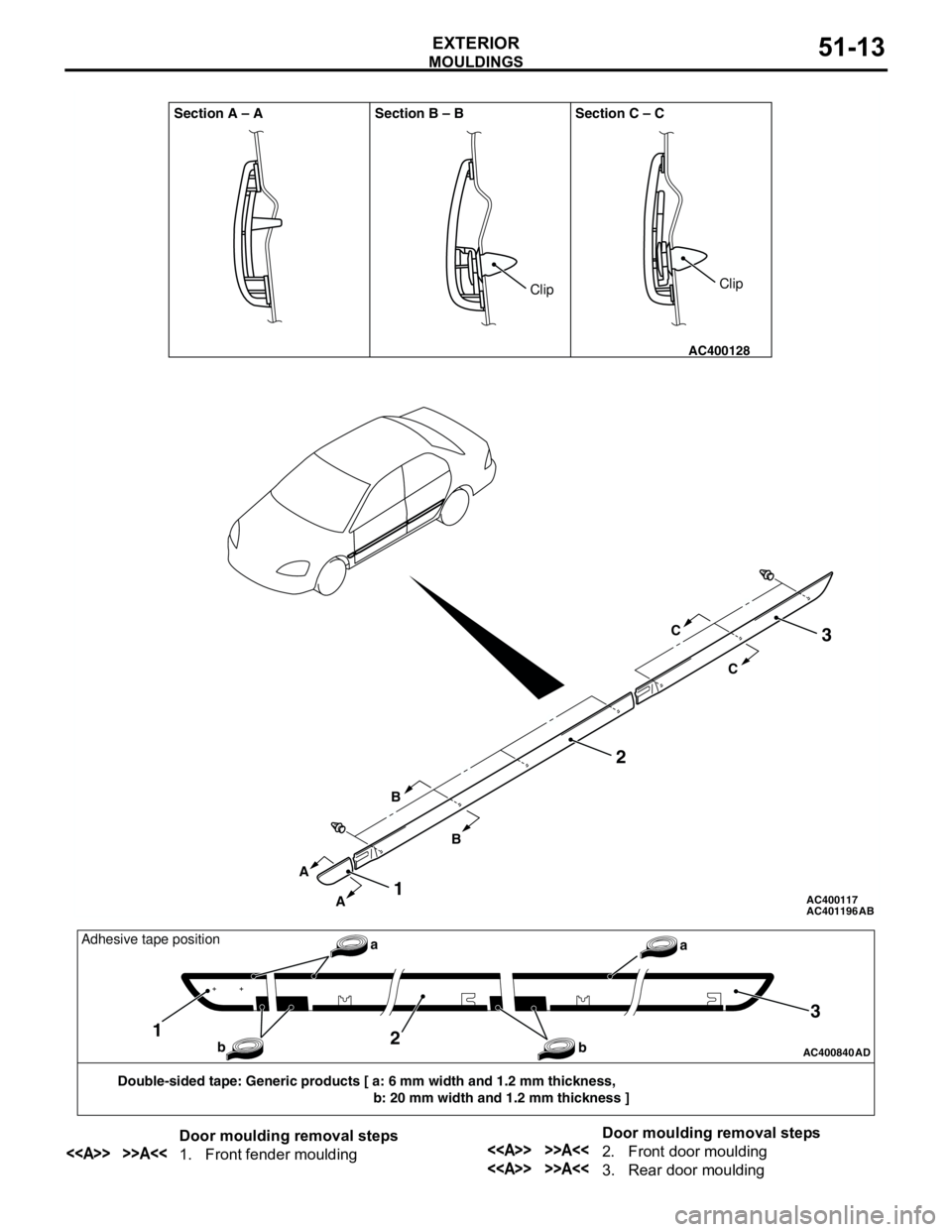
Double-sided tape: Generic products [ a: 6 mm width and 1.2 mm thickness,
b: 20 mm width and 1.2 mm thickness ]
12
3
a
b baAdhesive tape position
Door moulding removal steps
<> >>A<<1. Front fender mouldingDoor moulding removal steps<> >>A<<2. Front door moulding
<> >>A<<3. Rear door moulding
Page 352 of 788
Page 353 of 788
SIDE AIR DAM
EXTERIOR51-15
SIDE AIR DAM
ADHESIVEM1511000500437
SIDE AIR DAM
REMOVAL AND INSTALLATIONM1511005500238
Item Specification
Side air dam Double-sided tape
4 mm width and 1.2 mm thickness
AC303877
Clip
Clip Section A – A
AD
1
A A
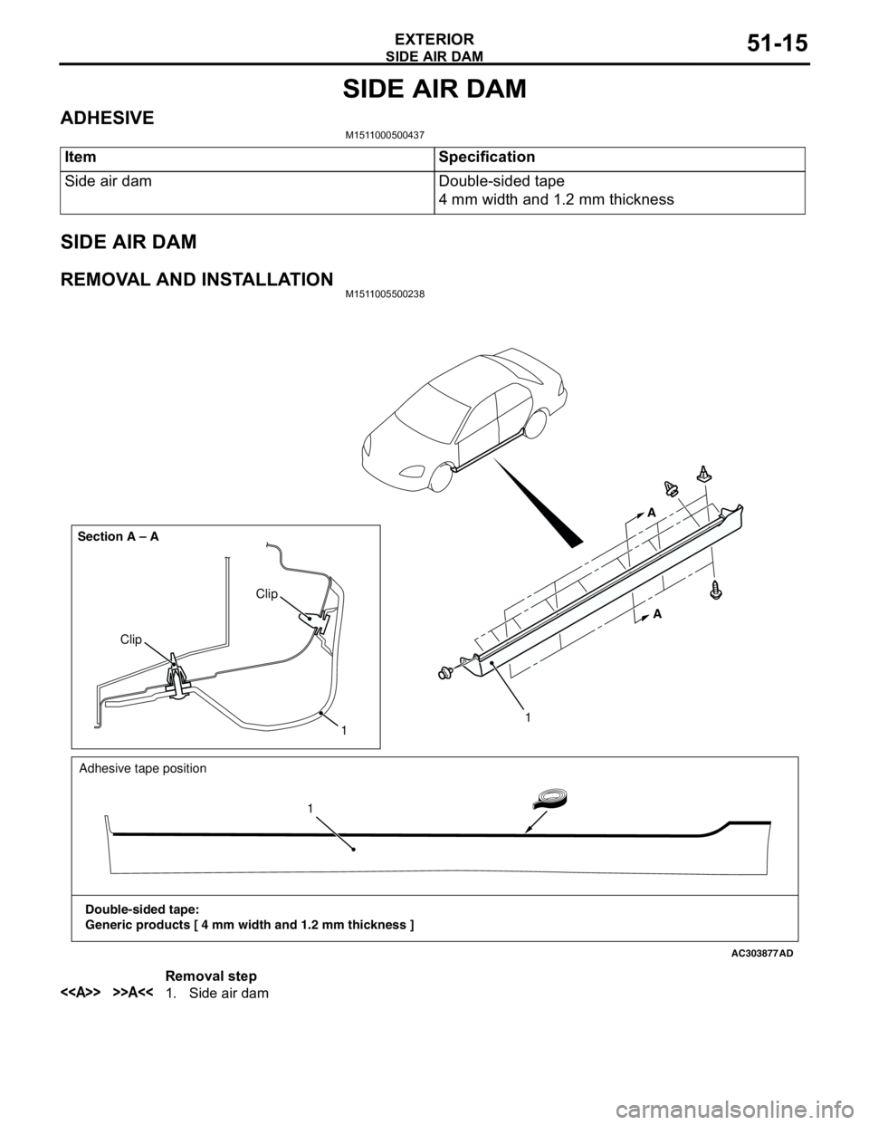
Adhesive tape position
Double-sided tape:
Generic products [ 4 mm width and 1.2 mm thickness ]11
Removal step
<> >>A<<1. Side air dam
Page 354 of 788
Page 356 of 788
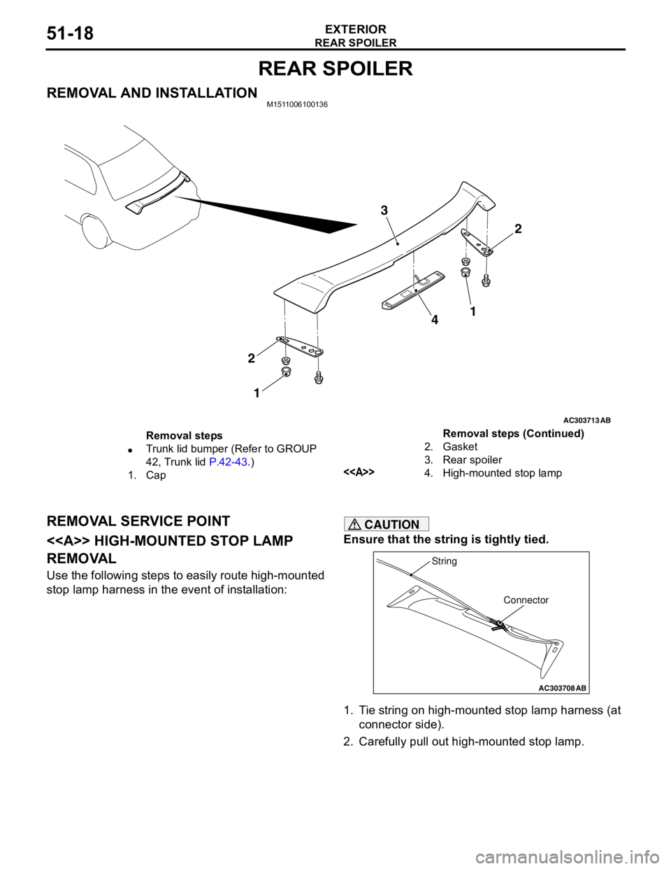
REAR SPOILER
EXTERIOR51-18
REAR SPOILER
REMOVAL AND INSTALLATIONM1511006100136
REMOVAL SERVICE POINT
<> HIGH-MOUNTED STOP LAMP
REMOVAL
Use the following steps to easily route high-mounted
stop lamp harness in the event of installation:
CAUTION
Ensure that the string is tightly tied.
1. Tie string on high-mounted stop lamp harness (at
connector side).
2. Carefully pull out high-mounted stop lamp.
AC303713
2 3
4
2
1
AB
1
Removal steps
•Trunk lid bumper (Refer to GROUP
42, Trunk lid P.42-43.)
1. Cap2. Gasket
3. Rear spoiler
<>4. High-mounted stop lampRemoval steps (Continued)
AC303708
Connector String
AB
Page 362 of 788
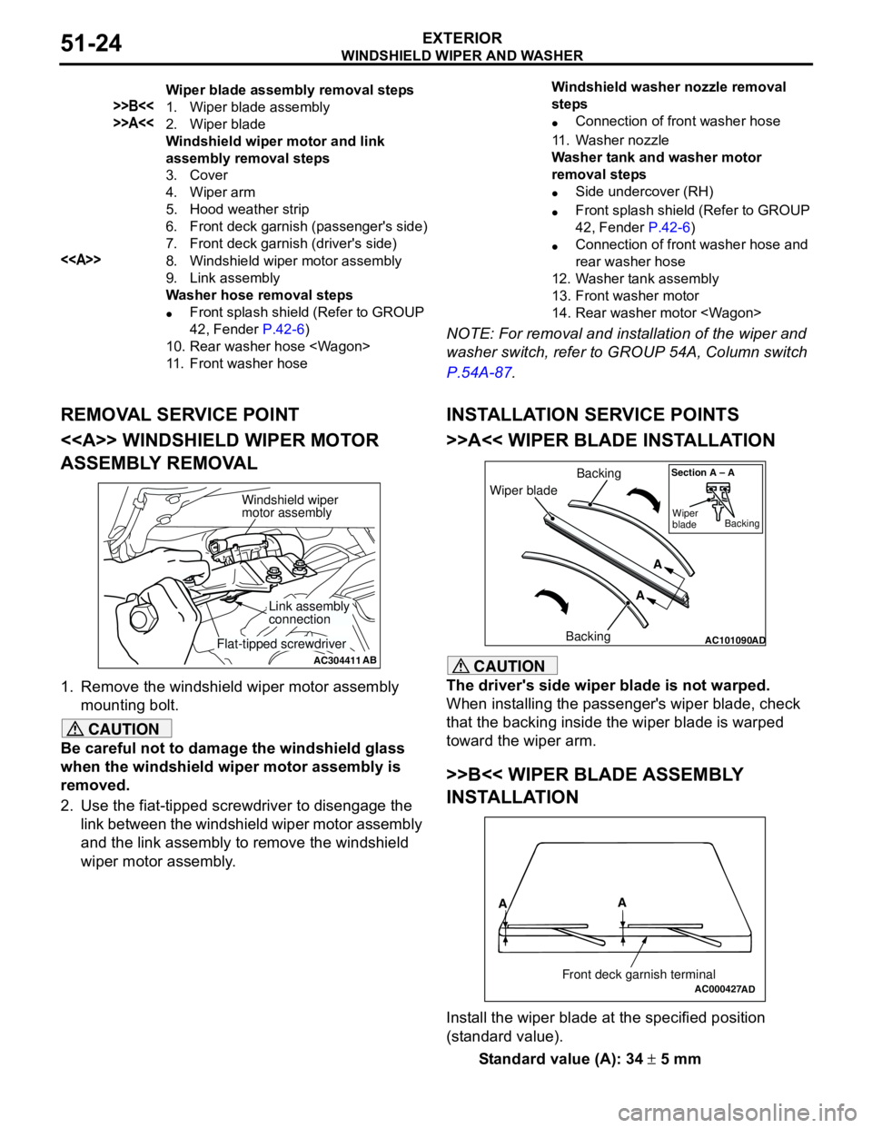
WINDSHIELD WIPER AND WASHER
EXTERIOR51-24
NOTE: For removal and installation of the wiper and
washer switch, refer to GROUP 54A, Column switch
P.54A-87.
REMOVAL SERVICE POINT
<> WINDSHIELD WIPER MOTOR
ASSEMBLY REMOVAL
1. Remove the windshield wiper motor assembly
mounting bolt.
CAUTION
Be careful not to damage the windshield glass
when the windshield wiper motor assembly is
removed.
2. Use the fiat-tipped screwdriver to disengage the
link between the windshield wiper motor assembly
and the link assembly to remove the windshield
wiper motor assembly.
INSTALLATION SERVICE POINTS
>>A<< WIPER BLADE INSTALLATION
CAUTION
The driver's side wiper blade is not warped.
When installing the passenger's wiper blade, check
that the backing inside the wiper blade is warped
toward the wiper arm.
>>B<< WIPER BLADE ASSEMBLY
INSTALLATION
Install the wiper blade at the specified position
(standard value).
Standard value (A): 34 ± 5 mm
Wiper blade assembly removal steps
>>B<<1. Wiper blade assembly
>>A<<2. Wiper blade
Windshield wiper motor and link
assembly removal steps
3. Cover
4. Wiper arm
5. Hood weather strip
6. Front deck garnish (passenger's side)
7. Front deck garnish (driver's side)
<>8. Windshield wiper motor assembly
9. Link assembly
Washer hose removal steps
•Front splash shield (Refer to GROUP
42, Fender P.42-6)
10. Rear washer hose
11. Front washer hoseWindshield washer nozzle removal
steps
•Connection of front washer hose
11. Washer nozzle
Washer tank and washer motor
removal steps
•Side undercover (RH)
•Front splash shield (Refer to GROUP
42, Fender P.42-6)
•Connection of front washer hose and
rear washer hose
12. Washer tank assembly
13. Front washer motor
14. Rear washer motor
AC304411AB
Windshield wiper
motor assembly
Link assembly
connection
Flat-tipped screwdriverAC101090AD
Wiper bladeBacking
BackingA
A
Section A – A
Wiper
bladeBacking
AC000427
A
A
Front deck garnish terminalAD
Page 367 of 788
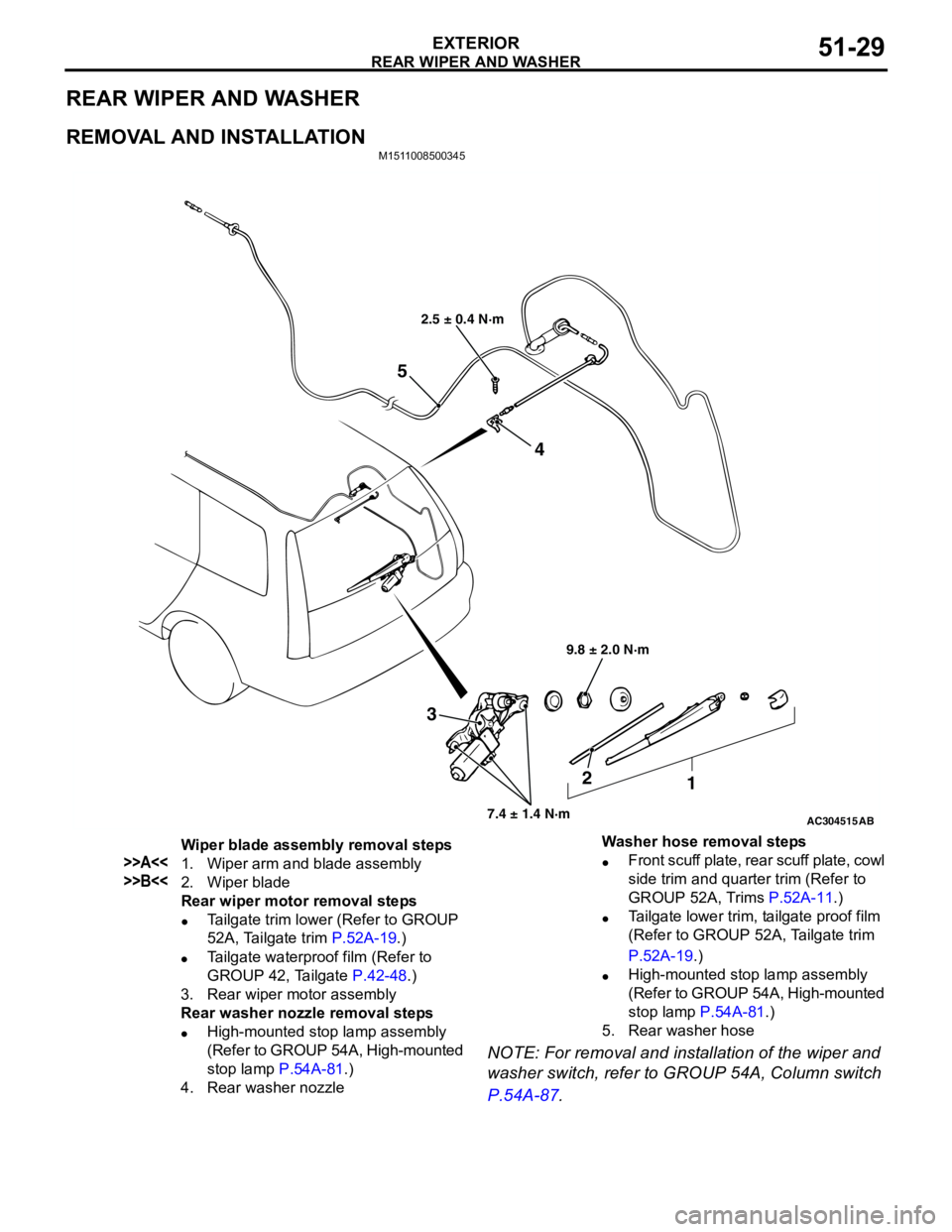
REAR WIPER AND WASHER
EXTERIOR51-29
REAR WIPER AND WASHER
REMOVAL AND INSTALLATION
M1511008500345
NOTE: For removal and installation of the wiper and
washer switch, refer to GROUP 54A, Column switch
P.54A-87.
AC304515
2.5 ± 0.4 N·m
9.8 ± 2.0 N·m
7.4 ± 1.4 N·m
3
2
1 4
5
AB
Wiper blade assembly removal steps
>>A<<1. Wiper arm and blade assembly
>>B<<2. Wiper blade
Rear wiper motor removal steps
•Tailgate trim lower (Refer to GROUP
52A, Tailgate trim P.52A-19.)
•Tailgate waterproof film (Refer to
GROUP 42, Tailgate P.42-48.)
3. Rear wiper motor assembly
Rear washer nozzle removal steps
•High-mounted stop lamp assembly
(Refer to GROUP 54A, High-mounted
stop lamp P.54A-81.)
4. Rear washer nozzleWasher hose removal steps
•Front scuff plate, rear scuff plate, cowl
side trim and quarter trim (Refer to
GROUP 52A, Trims P.52A-11.)
•Tailgate lower trim, tailgate proof film
(Refer to GROUP 52A, Tailgate trim
P.52A-19.)
•High-mounted stop lamp assembly
(Refer to GROUP 54A, High-mounted
stop lamp P.54A-81.)
5. Rear washer hose
Page 370 of 788
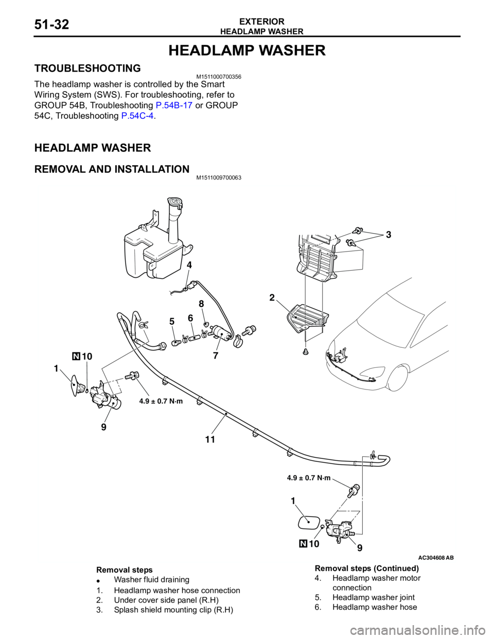
HEADLAMP WASHER
EXTERIOR51-32
HEADLAMP WASHER
TROUBLESHOOTINGM1511000700356
The headlamp washer is controlled by the Smart
Wiring System (SWS). For troubleshooting, refer to
GROUP 54B, Troubleshooting P.54B-17 or GROUP
54C, Troubleshooting P.54C-4.
HEADLAMP WASHER
REMOVAL AND INSTALLATIONM1511009700063
AC304608AB
10N
2
4
56
8
7
1
9
11
9
1
10N
4.9 ± 0.7 N·m 4.9 ± 0.7 N·m
3
Removal steps
•Washer fluid draining
1. Headlamp washer hose connection
2. Under cover side panel (R.H)
3. Splash shield mounting clip (R.H)4. Headlamp washer motor
connection
5. Headlamp washer joint
6. Headlamp washer hose Removal steps (Continued)
Page 376 of 788
DOOR MIRROR
EXTERIOR51-38
COMMENTS ON TROUBLE SYMPTOM
The heated door mirrors should works for
approximately 11 minutes when the rear defogger
switch is turned on. If the mirror heater does not work
for the specified period, the defogger relay circuit
(heated door mirror power supply circuit) may be
defective.
Possible causes
•Damaged harness wires and connectors
DIAGNOSIS PROCEDURE
STEP 1. Check the rear window defogger.
Check that the rear window defogger system should
work normally.
Q: Is the check result normal?
YES :
Go to Step 2.
NO : Troubleshoot the rear window defogger
(Refer to GROUP 55,
TroubleshootingP.55-42).
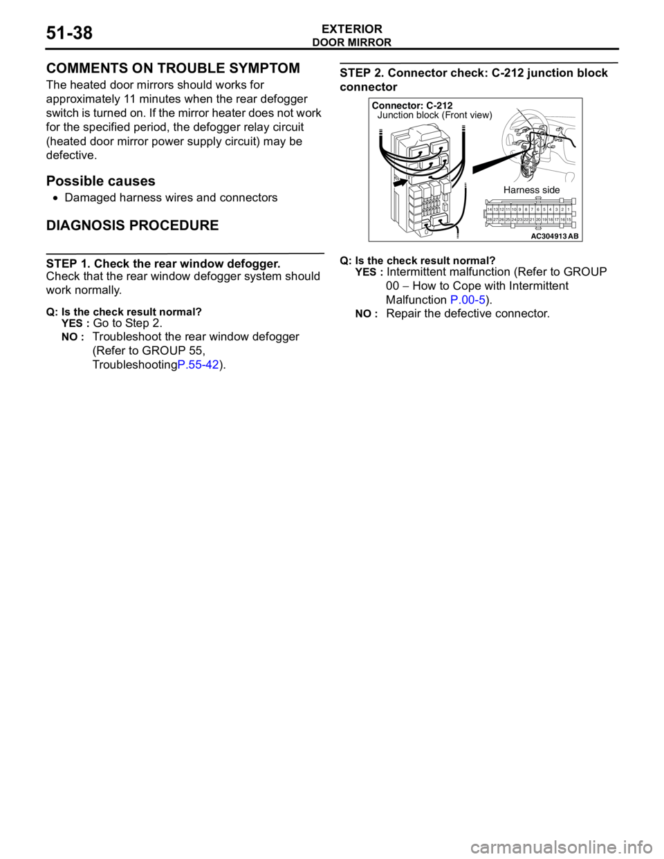
STEP 2. Connector check: C-212 junction block
connector
Q: Is the check result normal?
YES :
Intermittent malfunction (Refer to GROUP
00 − How to Cope with Intermittent
Malfunction P.00-5).
NO : Repair the defective connector.
AC304913
21716151718 201912345 623 222425282627981011141213
Connector: C-212
Harness side
AB
Junction block (Front view)
Page 378 of 788
DOOR MIRROR
EXTERIOR51-40
COMMENTS ON TROUBLE SYMPTOM
If either of the heated door mirrors does not work, the
door mirror assembly may be defective.
Possible causes
•Malfunction of the door mirror assembly
•Damaged harness wires and connectors
DIAGNOSIS PROCEDURE
Step 1. Verify the operation of each heated door
mirror.
Q: Which door mirror does not heat?
Door mirror (RH) :
Go to Step 2.
Door mirror (LH) : Go to Step 9.
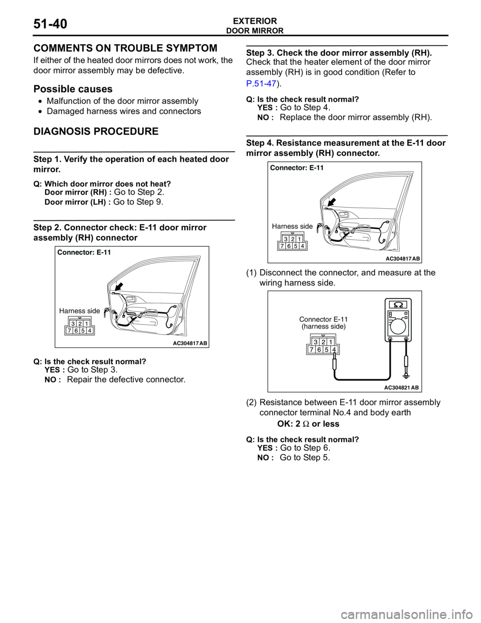
Step 2. Connector check: E-11 door mirror
assembly (RH) connector
Q: Is the check result normal?
YES :
Go to Step 3.
NO : Repair the defective connector.
Step 3. Check the door mirror assembly (RH).
Check that the heater element of the door mirror
assembly (RH) is in good condition (Refer to
P.51-47).
Q: Is the check result normal?
YES :
Go to Step 4.
NO : Replace the door mirror assembly (RH).
Step 4. Resistance measurement at the E-11 door
mirror assembly (RH) connector.
(1) Disconnect the connector, and measure at the
wiring harness side.
(2) Resistance between E-11 door mirror assembly
connector terminal No.4 and body earth
OK: 2 Ω or less
Q: Is the check result normal?
YES :
Go to Step 6.
NO : Go to Step 5.
AC304817
Connector: E-11
Harness side
AB
AC304817
Connector: E-11
Harness side
AB
AC304821
Connector E-11
(harness side)
AB