MITSUBISHI MONTERO 1987 1.G Workshop Manual
Manufacturer: MITSUBISHI, Model Year: 1987, Model line: MONTERO, Model: MITSUBISHI MONTERO 1987 1.GPages: 284, PDF Size: 14.74 MB
Page 261 of 284
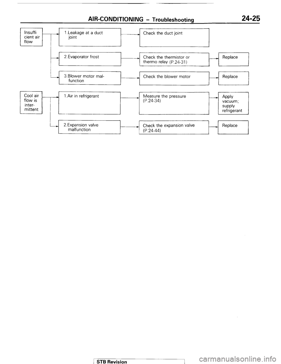
AIR-CONDITIONING - Troubleshooting 24-25
lnsuffi
cient air
flow ) 1 .Leakage at a duct
joint . Check the duct joint
- 2.Evaporator frost
D Check the thermistor or
therm0 relay (P.24-31) A Replace
3.Blower motor mal-
function + Check the blower motor - Replace
+
Cool air
.
flow is 1 .Air in refrigerant ) Measure the pressure
(P.24-34) - Apply
inter- vacuum;
mittent supply
refrigerant
i--) 2.Expansion valve
malfunction Check the expansion valve
* (P.24-44) _ Replace STB Revision
Page 262 of 284
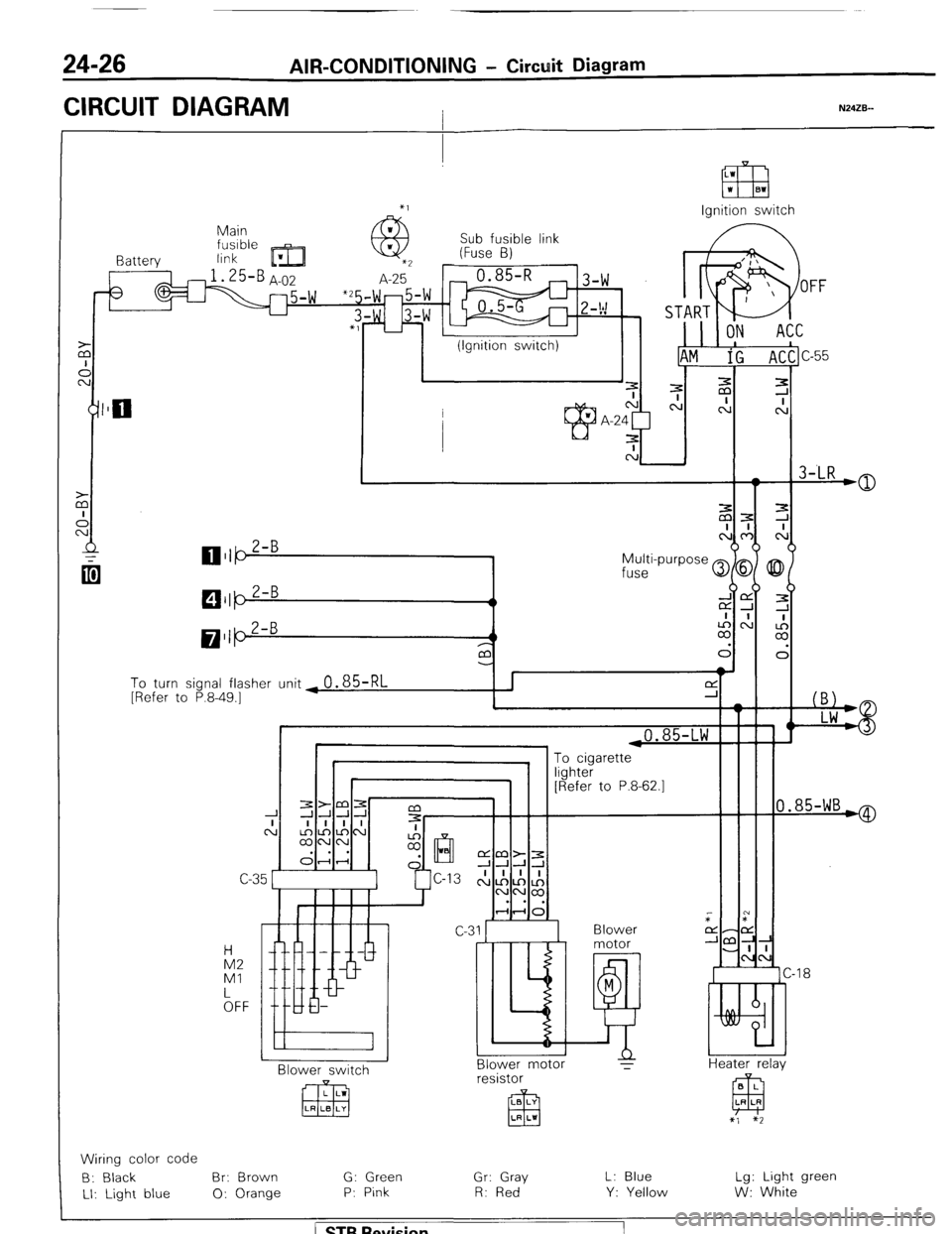
24-26 AIR-CONDITIONING - Circuit Diagram
CIRCUIT DIAGRAM I N24ZB--
Ignition switch
Main
link Sub fusible link
(Fuse B)
I Battery
3
To turn signal flasher unit ~
0.85-RL [Refer to P.8-49.1
i
I 1 ,0.85-LW F
0.85-WB*
“yl lLG1 [Refer to P.8-62.1
C-C
Blower
motor
M
E!! Blower motor
T IA2
Ml
kFF -18
Heater relav N BI ower switch B L
EEJ LR LR resistor
LB LY
El3 LR LI
x’, $2
Wiring color code
B: Black Br: Brown G: Green
Gr: Gray L: Blue Lg: Light green
LI: Light blue 0: Orange P: Pink R: Red
Y: Yellow W: White
/ ST6 Revision
Page 263 of 284
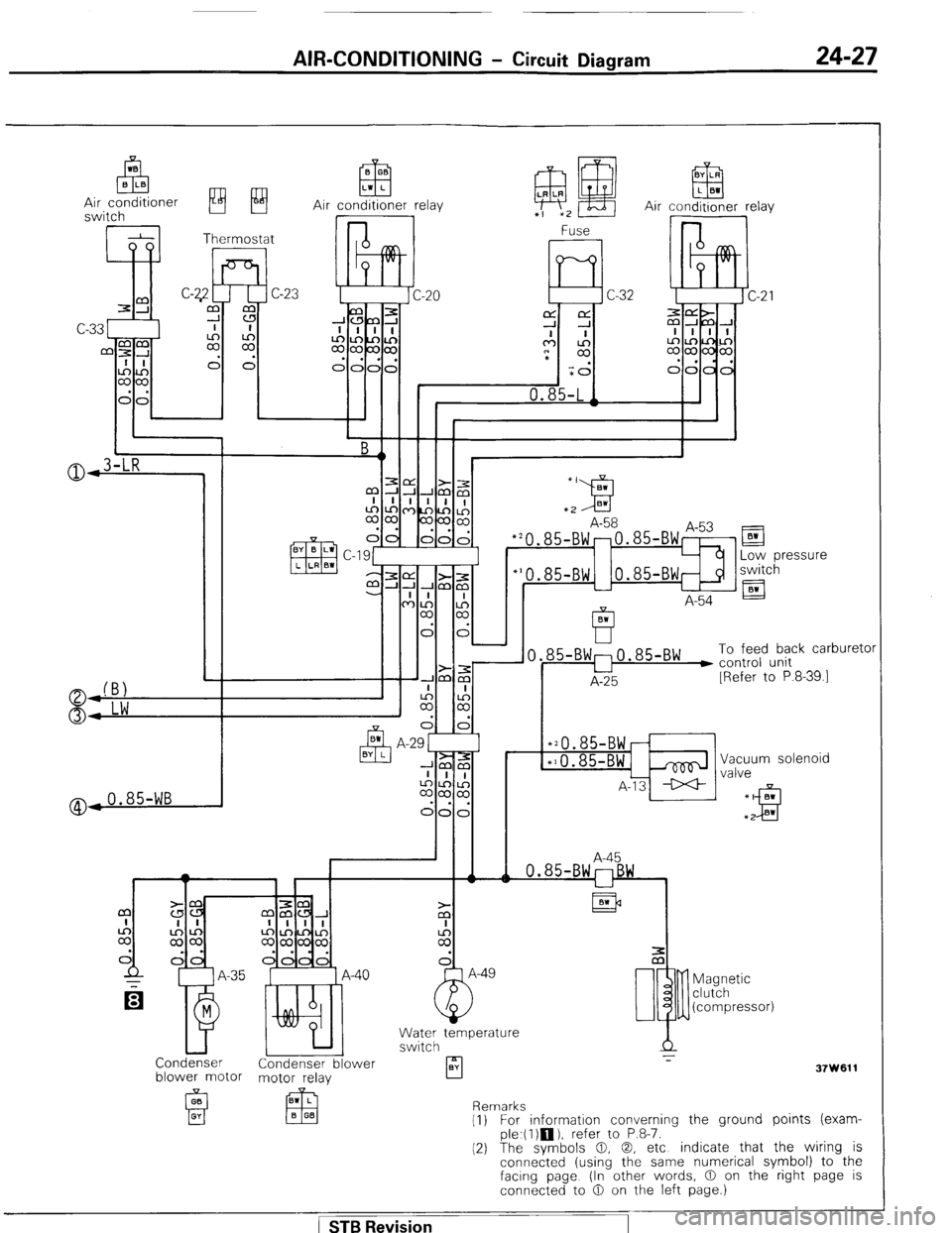
AIR-CONDITIONING - Circuit Diagram 24-27
Air conditioner relay
@,0.85-WB
El
Low pressure
switch
A-54 El
85-BW:0.85-BW ) To feed back carburetc
u control unit
A-25 [Refer to P.8-39.1
*20.85-BWr
*10.85-BWi& Vacuum solenoid
A-13 ++ valve
A-45
Condenser Condenser blower
blower motor motor relay
A
rl z-
BY
37W611 Magnetic
clutch
(compressor)
Remarks
(1) For information converning the ground points (exam-
ple.(l)m), refer to P.8-7.
(2) The symbols 0, 0, etc indicate that the wiring is
connected (using the same numerical symbol) to the
facing page (In other words, 0 on the right page is
connected to 0 on the left page.)
( STB Revision
Page 264 of 284
24-28 AIR-CONDITIONING-Safety Precautions
SAFETY PRECAUTIONS N24PAAB
SAFETY PRECAUTIONS
I
The refrigerant used in all air-conditioning installations is R-12. It is transparent and colorless in both the liquid and
vapor state. Since it has a boiling point of -29.8T (-21.7”F). at atmospheric pressure, it will be a vapor at all normal
temperatures and pressures. The vapor is heavier than air, non- flammable, and nonexplosive. It is nonpoisonous
except when it is in direct contact with open flame. It is noncorrosive except when combined with water. The
following precautions must be observed when handling R-12.
Caution
Wear
safety goggles when servicing the refrigeration system.
R-12 evaporates so rapidly at normal atmospheric pressures and temperatures that it tends to freeze anything it
contacts. For this reason, extreme care must be taken to prevent any liquid refrigerant from contacting the skin and
especially the eyes.
Always wear safety goggles when servicing the refrigeration part of the air- conditioning system. Keep a bottle of
sterile mineral oil handy when working on the refrigeration system. Should any liquid refrigerant get into the eyes,
use a few drops of mineral oil to wash them out. RI12 is rapidly absorbed by the oil. Next, splash the eyes with
plenty of cold water. Call your doctor immediately even though irritation has ceased after treatment.
Caution
Do not heat R-12 above 52°C (125°F).
In most instances, moderate heat is required to bring the pressure of the refrigerant in its container above the
pressure of the system when charging or adding refrigerant. A bucket or large pan of hot water not over 52°C
(125°F) is all the heat required for this purpose. Do not heat the refrigerant container with a blow torch or any other
means that would raise temperature and pressure above this temperature. Do not weld or steam clean on or near
the system components or refrigerant lines.
Caution
Keep R-12 containers upright when charging the system.
When metering R-12 into the refrigeration system, keep the supply tank or cans in an upright position. If the
refrigerant container is on its side or upside down, liquid refrigerant will enter the system and damage the
compressor.
Caution
Always work in a well-ventilated room.
Good ventilation is vital in the working area. Always discharge the refrigerant into the service bay exhaust system
or outside the building. Large quantities of refrigerant vapor in a small, poorly ventilated room can displace the air
and cause suffocation.
Although R-12 vapor is normally nonpoisonous, contact with an open flame can cause the vapor to become very
poisonous. Do not discharge large quantities of refrigerant in an area having an open flame. A poisonous gas is
producted when using the flame-type leak detector. Avoid inhaling the fumes from the leak detector.
Caution
Do not allow liquid refrigerant to touch bright metal.
Refrigerant will tarnish bright metal and chrome surfaces, and in combination with moisture’can severely corrode
all metal surfaces.
/ STB Revision
-I
Page 265 of 284
AIR-CONDITIONING-Service Adjustment Procedures
SERVICE ADJUSTMENT PROCQDURES 24-29 N24FDAD
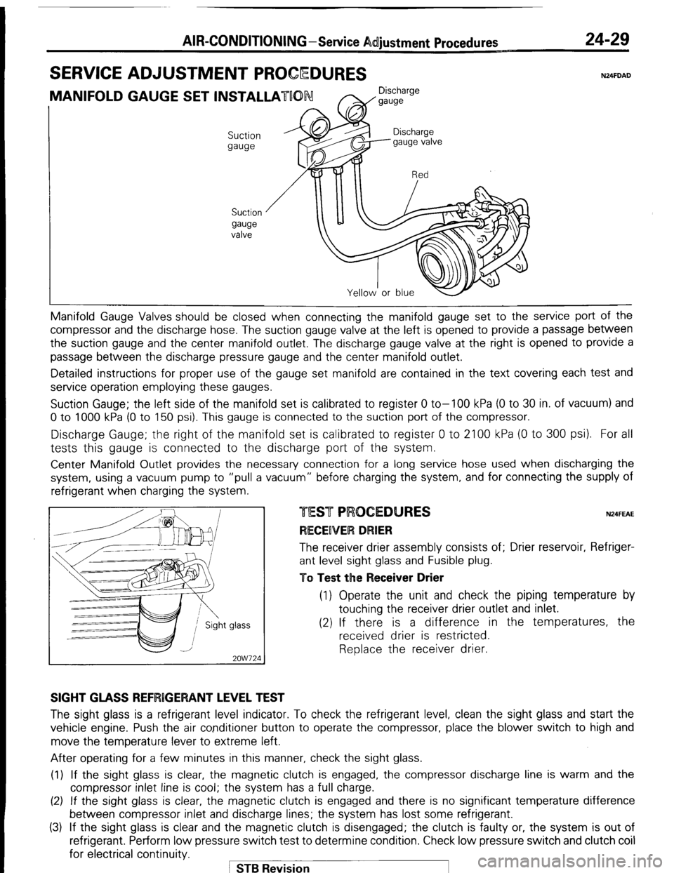
MANIFOLD GAUGE SET INSTALLATUON Discharge
W gauge
Suction
gauge
Suction
gauge
valve Manifold Gauge Valves should be closed
when connecting the manifold gauge set to the service port of the
compressor and the discharge hose. The suction gauge valve at the left is opened to provide a passage between
the suction gauge and the center manifold outlet. The discharge gauge valve at the right is opened to provide a
passage between the discharge pressure gauge and the center manifold outlet.
Detailed instructions for proper use of the gauge set manifold are contained in the text covering each test and
service operation employing these gauges.
Suction Gauge; the left side of the manifold set is calibrated to register 0 to-100 kPa (0 to 30 in. of vacuum) and
0 to 1000 kPa (0 to 150 psi). This gauge is connected to the suction port of the compressor.
Discharge Gauge; the right of the manifold set is calibrated to register 0 to 2100 kPa (0 to 300 psi). For all
tests this gauge is connected to the discharge port of the system.
Center Manifold Outlet provides the necessary connection for a long service hose used when discharging the
system, using a vacuum pump to “pull a vacuum” before charging the system, and for connecting the supply of
refrigerant when charging the system
glass -
2OW724 N24FEAE The receiver drier assembly consists of; Drier reservoir, Refriger-
ant level sight glass and Fusible plug.
To Test the Receiver Drier (1) Operate the unit and check the piping temperature by
touching the receiver drier outlet and inlet.
(2) If there is a difference in the temperatures, the
received drier is restricted.
Replace the receiver drier.
SIGHT GLASS REFRlGERANT LEVEL TEST The sight glass is a refrigerant level indicator. To check the refrigerant level, clean the sight glass and start the
vehicle engine. Push the air conditioner button to operate the compressor, place the blower switch to high and
move the temperature lever to extreme left.
After operating for a few minutes in this manner, check the sight glass.
(1) If the sight glass is clear, the magnetic clutch is engaged, the compressor discharge line is warm and the
compressor inlet line is cool; the system has a full charge.
(2) If the sight glass is clear, the magnetic clutch is engaged and there is no significant temperature difference
between compressor inlet and discharge lines; the system has lost some refrigerant.
(3) If the sight glass is clear and the magnetic clutch is disengaged; the clutch is faulty or, the system is out of
refrigerant. Perform low pressure switch test to determine condition. Check low pressure switch and clutch coil
for electrical continuity.
1 STB Revision
Page 266 of 284
24-30 AIR-CONDITIONING -Service Adjustunent Procedures
(4) If the sight glass shows foam or bubbles, the systpm could be low on charge. Occasional foam or bubbles are
normal when the ambient temperature is above 43”C(110”F) or below 21”C(7O”F).
Adjust the engine speed to 1,500 rpm. Block the airflow through the condenser to increase the compressor
discharge pressure to 1,422 to 1,520 kPa (20$ to 220 dsi). If sight glass still shows bubbles or foam, system charge
level is low.
The refrigerant system will not be low on charge unless there is a leak. Find and repair the leak. If the leak can be
repaired without discharging the system an oil level check is not necessary. Use the procedure for correcting low
refrigerant level found in the Refrigerant Sy$em Service Procedure Section.
FUSIBLE PLUG
When ambient temperature of the fusible plug reach& 105~221~F), the fusible plug melts and the refrigerant in
the system is released.
Once the fusible plug is operated, it cannot be used again.
SO, it is necessary to install new one and charge the refrigerant in the system.
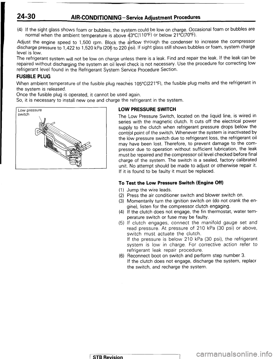
Low pressure
switch , LOW PRESSURE SWITCH
The Low Pressure Switch, located on the liquid line, is wired in
series with the magnetic clutch. It cuts off the electrical power
supply to the clutch when refrigerant pressure drops below the
cont$ol point of the switch. Whenever the system is inactivated by
the low pressure switch due to refrigerant loss, the refrigerant oil
may have been lost. Therefore, to prevent damage to the com-
pressor due to operation without sufficient lubrication, the leak
must be repaired and the compressor oil level checked before final
charge of the system. The switch is a sealed, factory calibrated
unit. No attempt should be made to adjust or otherwise repair it.
If it is found to be faulty it must be replaced.
To Test the Low Pressure Switch (Engine Off)
(1) Jump the wire leads.
(2) Press the air conditioner switch and blower switch on.
(3) Momentarily turn the ignition switch on (do not crank the en-
gine), listen for the compressor clutch engaging.
(4) If the clutch does not engage, the fin thermostat, water tem-
perature switch or fuse may be faulty.
(5) If clutch engages, connect the manifold gauge set and
read pressure. At pressure of 210 kPa (30 psi) or above,
switch must actuate the clutch.
If the pressure is below 210 kPa (30 psi), the refrigerant
system is low in charge. For corrective action refer to
refrigerant leak repair procedure.
(6) Reconnect boot on switch and perform step number 3.
If the clutch does not engage, discharge the system, replace
the switch, and recharge the system.
[
STB Revision
Page 267 of 284
AIR-CONDITIONING-Service Adiustment Procedures 24-31
FREEZE UP CONTROL
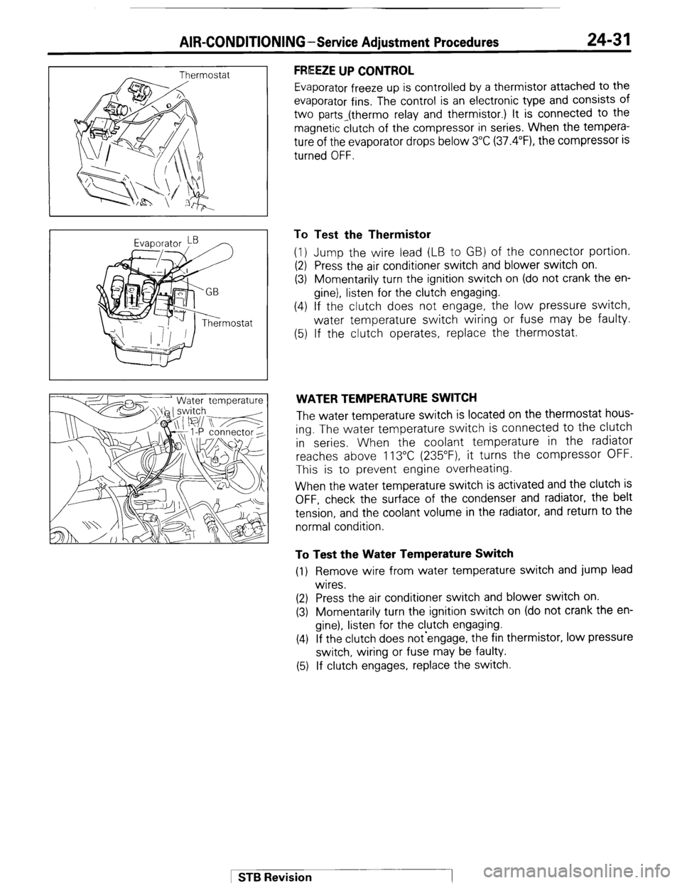
Evaporator freeze up is controlled by a thermistor attached to the
evaporator fins. The control is an electronic type and consists of
two parts_(thermo relay and thermistor.) It is connected to the
magnetic clutch of the compressor in series. When the tempera-
ture of the evaporator drops below 3°C (37.4”F), the compressor is
turned OFF.
To Test the Thermistor
(1) Jump the wire lead (LB to GB) of the connector portion.
(2) Press the air conditioner switch and blower switch on.
(3) Momentarily turn the ignition switch on (do not crank the en-
gine), listen for the clutch engaging.
(4) If the clutch does not engage, the low pressure switch,
water temperature switch wiring or fuse may be faulty.
(5) If the clutch operates, replace the thermostat.
WATER TEMPERATURE SWITCH
The water temperature switch is located on the thermostat hous-
ing. The water temperature switch is connected to the clutch
in series. When the coolant temperature in the radiator
reaches above 113°C (235”F), it turns the compressor OFF.
This is to prevent engine overheating.
When the water temperature switch is activated and the clutch is
OFF, check the surface of the condenser and radiator, the belt
tension, and the coolant volume in the radiator, and return to the
normal condition.
To Test the Water Temperature Switch
(1) Remove wire from water temperature switch and jump lead
wires.
(2) Press the air conditioner switch and blower switch on.
(3) Momentarily turn the ignition switch on (do not crank the en-
gine), listen for the clutch engaging.
(4) If the clutch does not-engage, the fin thermistor, low pressure
switch, wiring or fuse may be faulty.
(5) If clutch engages, replace the switch.
1 STB Revision
Page 268 of 284
24-32 AIR-CONDITIONING-Service Adjustment Procedures
i--
9 >
@
r
2ouo319
- 2OW627 I
Suction gauge Discharge w-w
/ I
Suction
ww Discharge
w-w
2OUO306
Suction
w-w Discharge
gauge
2OUO307
AIR CONDITIONER SWITCH
To jest the Air Conditioner Switch
(1) Disconnect the harness connector for the air conditioner
switch.
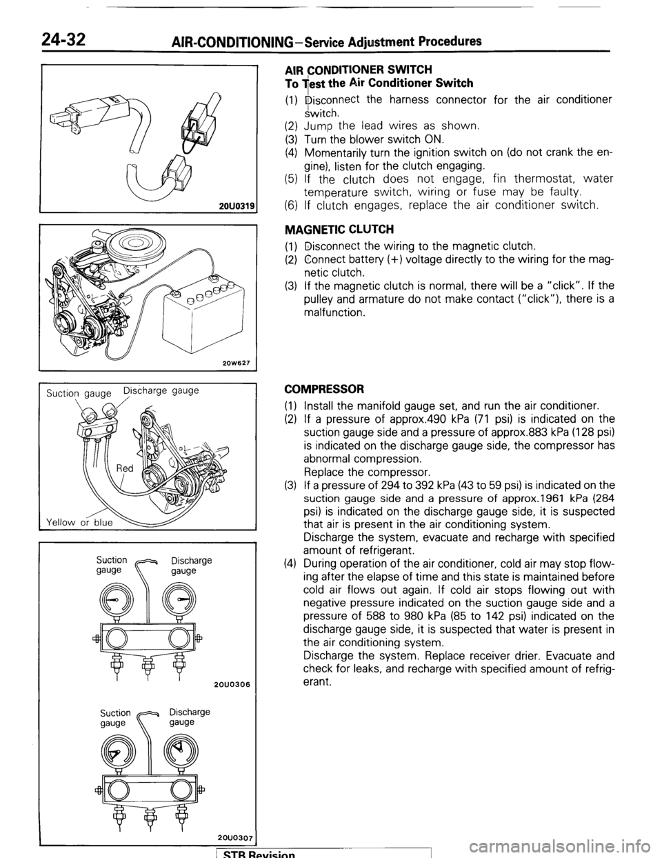
(2) Jump the lead wires as shown.
(3) Turn the blower switch ON.
(4) Momentarily turn the ignition switch on (do not crank the en-
gine), listen for the clutch engaging.
(5) If the clutch does not engage, fin thermostat, water
temperature switch, wiring or fuse may be faulty.
(6) If clutch engages, replace the air conditioner switch.
MAGNETIC CLUTCH
(1) Disconnect the wiring to the magnetic clutch.
(2) Connect battery (+) voltage directly to the wiring for the mag-
netic clutch.
(3) If the magnetic clutch is normal, there will be a “click”. If the
pulley and armature do not make contact (“click”), there is a
malfunction.
COMPRESSOR
(1) Install the manifold gauge set, and run the air conditioner.
(2) If a pressure of approx.490 kPa (71 psi) is indicated on the
suction gauge side and a pressure of approx.883 kPa (128 psi)
is indicated on the discharge gauge side, the compressor has
abnormal compression.
Replace the compressor.
(3) If a pressure of 294 to 392 kPa (43 to 59 psi) is indicated on the
suction gauge side and a pressure of approx.1961 kPa (284
psi) is indicated on the discharge gauge side, it is suspected
that air is present in the air conditioning system.
Discharge the system, evacuate and recharge with specified
amount of refrigerant.
(4) During operation of the air conditioner, cold air may stop flow-
ing after the elapse of time and this state is maintained before
cold air flows out again. If cold air stops flowing out with
negative pressure indicated on the suction gauge side and a
pressure of 588 to 980 kPa (85 to 142 psi) indicated on the
discharge gauge side, it is suspected that water is present in
the air conditioning system.
Discharge the system. Replace receiver drier. Evacuate and
check for leaks, and recharge with specified amount of refrig-
erant.
/ STB Revision
Page 269 of 284
AIR-CONDITIONING-Service Adjustment Procedures 24-33
2080113
6
Refrigerant
Compressor
Cl”“” tester T-7
Leak
, tester
pick up
tube
b/
2OUO316
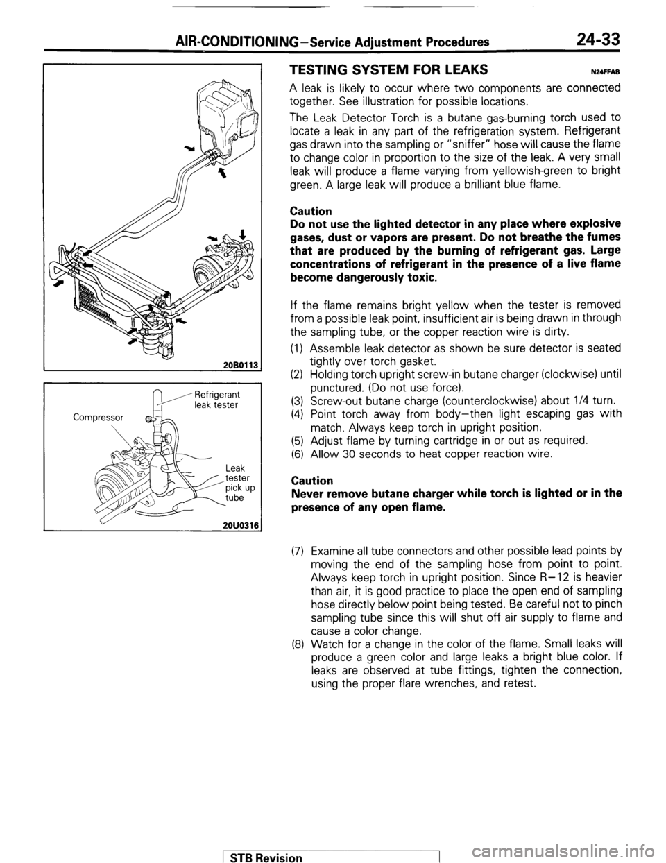
TESTING SYSTEM FOR LEAKS N24FFA8
A leak is likely to occur where two components are connected
together. See illustration for possible locations.
The Leak Detector Torch is a butane gas-burning torch used to
locate a leak in any part of the refrigeration system. Refrigerant
gas drawn into the sampling or “sniffer” hose will cause the flame
to change color in proportion to the size of the leak. A very small
leak will produce a flame varying from yellowish-green to bright
green. A large leak will produce a brilliant blue flame.
Caution
Do not use the lighted detector in any place where explosive
gases, dust or vapors are present. Do not breathe the
fumes
that are produced by the burning of refrigerant gas. Large
concentrations of refrigerant in the presence of a live flame
become dangerously toxic.
If the flame remains bright yellow when the tester is removed
from a possible leak point, insufficient air is being drawn in through
the sampling tube, or the copper reaction wire is dirty.
(1) Assemble leak detector as shown be sure detector is seated
tightly over torch gasket.
(2) Holding torch upright screw-in butane charger (clockwise) until
punctured. (Do not use force).
(3) Screw-out butane charge (counterclockwise) about l/4 turn.
(4) Point torch away from body-then light escaping gas with
match. Always keep torch in upright position.
(5) Adjust flame by turning cartridge in or out as required.
(6) Allow 30 seconds to heat copper reaction wire.
Caution
Never remove butane charger while torch is lighted or in the
presence of any open flame.
(7) Examine all tube connectors and other possible lead points by
moving the end of the sampling hose from point to point.
Always keep torch in upright position. Since R-12 is heavier
than air, it is good practice to place the open end of sampling
hose directly below point being tested. Be careful not to pinch
sampling tube since this will shut off air supply to flame and
cause a color change.
(8) Watch for a change in the color of the flame. Small leaks will
produce a green color and large leaks a bright blue color. If
leaks are observed at tube fittings, tighten the connection,
using the proper flare wrenches, and retest.
1 STB Revision
Page 270 of 284
24-34 AIR-CONDITIONING-Service Adiustment Procedures
r---- :
:ES
Dry bulb therr&neter
2OW825
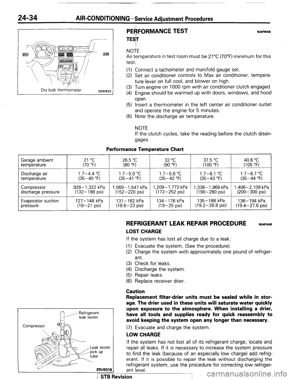
PEAFORMANCE TEST
TESI N24FWAB NOTE
Air temperature in test room must be 21°C (70°F) minimum for this
test.
(1) Connect a tachometer and manifold gauge set.
(2) Set air conditioner controls to Max air conditioner, tempera-
ture lever on full cool, and blower on high.
(3) Turn engine on 1000 rpm with air conditioner clutch engaged.
(4) Engine should be warmed up with doors, windows, and hood
open.
(5) Insert a thermometer in the left center air conditioner outlet
and operate the engine for 5 minutes.
(6) Note the discharge air temperature.
NOTE
If the clutch cycles, take the reading before the clutch disen-
gages.
Performance Temperature Chart Garage ambient
temperature
21 “C 26.5 “C 32 “C 37.5 “C 40.6 “C (70 “F) (80 “F) (90 “F) (100 “F) (I 05 “F)
Discharge air
temperature
Compressor
discharge pressure
Evaporator suction
pressure
1.7-4.4 “C 1.7-5.0 “C 1.7-5.6 “C 1.7-6.1 “C 1.7-6.7 “C (35-40 “F) (35-41 “F) (35-42 “F) (35-43 “F) (35-44 “F)
928- 1,322 kPa 1.069-1.547 kPa 1,209-1,772 kPa 1,336-1,969 kPa 1,406-2,109 kPa
(132-188 psi) (152-220 psi) (172-252 psi) (190-280 psi) (200-300 psi)
127-148 kPa
131-162 kPa 134-176 kPa 135- 188 kPa 136-194 kPa
(18-21 psi) (18.6-23 psi) (19-25 psi) (19.2-26.8 psi) (19.4-27.6 psi)
REFRIGERANT LEAK REPAIR PROCEDURE N24FnAB
LOST CHARGE If the system has lost all charge due to a leak:
(1) Evacuate the system. (See the procedure).
(2) Charge the system with approximately one pound of refriger-
ant.
(3) Check for leaks.
(4) Discharge the system.
(5) Repair leaks.
(6) Replace receiver drier.
Caution
Refrigerant
leak tester
Replacement filter-drier units must be sealed while in stor-
age. The drier used in these units will saturate water quickly
upon exposure to the atmosphere. When installing a drier,
have all tools and supplies ready for quick reassembly to
avoid keeping the system open any longer than necessary. (7) Evacuate and charge the system.
LOW CHARGE If the system has not lost all of its refrigerant charge; locate and
tester repair all leaks. If it is necessary to increase the system pressure
up to find the leak (because of an especially low charge) add refrig-
erant. If it is possible to repair the leak without discharging the
refrigerant system, use the procedure for correcting low refriger-
2OUO316 ant level.
1 STB Revision