MITSUBISHI MONTERO 1987 1.G Workshop Manual
Manufacturer: MITSUBISHI, Model Year: 1987, Model line: MONTERO, Model: MITSUBISHI MONTERO 1987 1.GPages: 284, PDF Size: 14.74 MB
Page 231 of 284
AUTOMATIC FREE-WHEELING HUB INDICATOR SYSTEM - Generallnformation 8-211
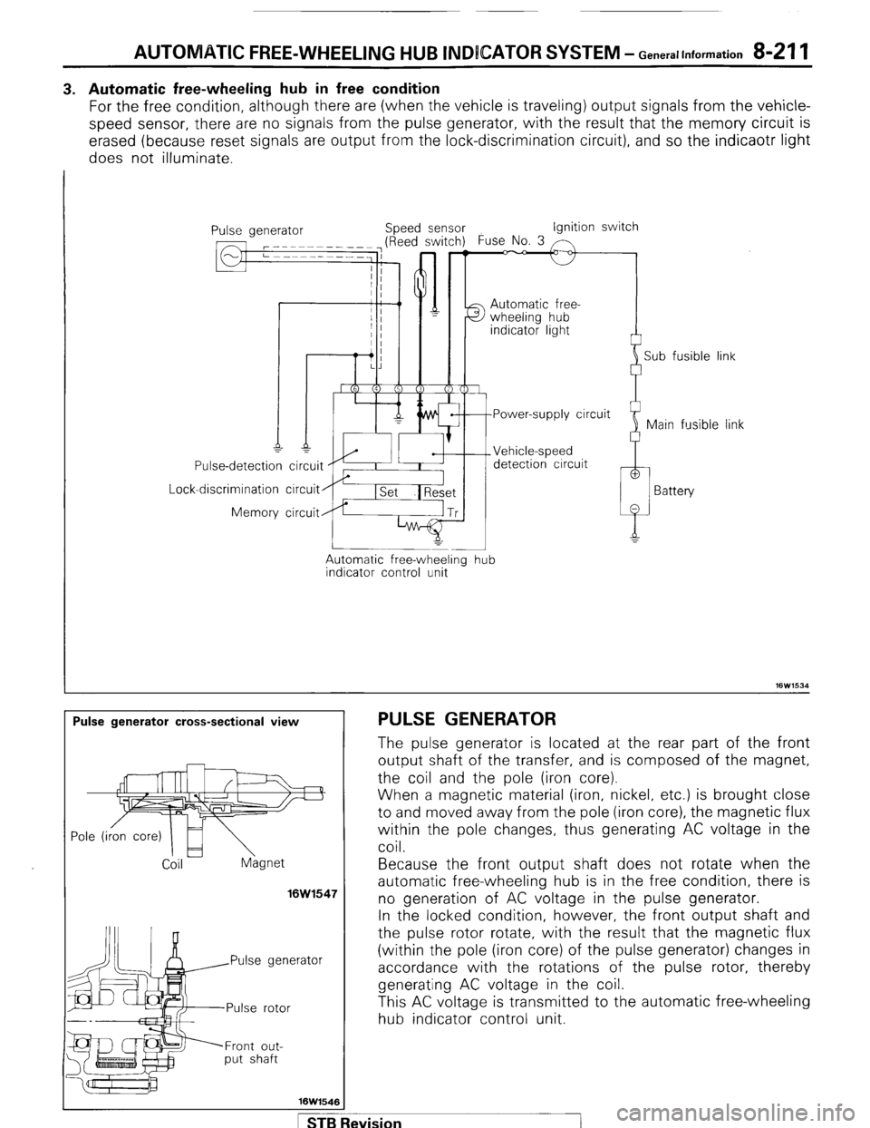
3. Automatic free-wheeling hub in free condition
For the free condition, although there are (when the vehicle is traveling) output signals from the vehicle-
speed sensor, there are no signals from the pulse generator, with the result that the memory circuit is
erased (because reset signals are output from the lock-discrimination circuit), and so the indicaotr light
does not illuminate.
I
Lock Use-detection
-discrimination
Memory ipeed sensor Ignition switch
Automatic free-
detection circuit
circuit
circuit
Automatic free-wheeling
indicator control unit -
hub i
Sub fusible link
link
Pulse generator cross-sectional view PULSE GENERATOR
Coil hgnet
16W1547
rator
Front out-
put shaft
16W1546 The pulse generator is located at the rear part of the front
output shaft of the transfer, and is composed of the magnet,
the coil and the pole (iron core).
When a magnetic material (iron, nickel, etc.) is brought close
to and moved away from the pole (iron core), the magnetic flux
within the pole changes, thus generating AC voltage in the
coil.
Because the front output shaft does not rotate when the
automatic free-wheeling hub is in the free condition, there is
no generation of AC voltage in the pulse generator.
In the locked condition, however, the front output shaft and
the pulse rotor rotate, with the result that the magnetic flux
(within the p o e I (’ Iron core) of the pulse generator) changes in
accordance with the rotations of the pulse rotor, thereby
generating AC voltage in the coil.
This AC voltage is transmitted to the automatic free-wheeling
hub indicator control unit.
STB Revision
Page 232 of 284
8-212 AUTOMATIC FREE-WHEELING HUB lNCDlCATOR SYSTEM - $%%60n’~at’on’
Speedometer
I
iensor Vehicle-speed
sensor
16W1506
12R0058
Circuit Diagram
16W153
SPECIFICATIONS
GENERAL SPECIFICATIONS VEHICLE-SPEED SENSOR (REED-TYPE SWITCH)
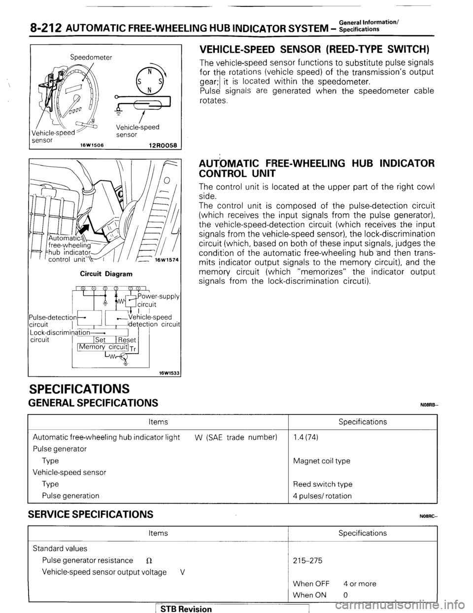
The vehicle-speed sensor functions to substitute pulse signals
for the rotations (vehicle speed) of the transmission’s output
gear;/ t i is located within the speedometer.
Pulse signals are generated when the speedometer cable
rotates.
AUTbMATlC FREE-WHEELING HUB INDICATOR
CONTROL UNIT
The control unit is located at the upper part of the right cowl
side.
The control unit is composed of the pulse-detection circuit
(which receives the input signals from the pulse generator),
the vehicle-speed-detection circuit (which receives the input
signals from the vehicle-speed sensor), the lock-discrimination
circuit (which, based on both of these input signals, judges the
condition of the automatic free-wheeling hub ‘and then trans-
mits indicator output signals to the memory circuit), and the
memory circuit (which “memorizes” the indicator output
signals from the lock-discrimination circuti).
Items
Automatic free-wheeling hub indicator light
Pulse generator
Type
Vehicle-speed sensor
Type
Pulse generation
SERVICE SPECIFICATIONS
Specifications
W (SAE trade number) 1.4(74)
Magnet coil type
Reed switch type
4 pulses/ rotation
NOORG-
Items Specifications
Standard values
Pulse generator resistance
R 215-275
Vehicle-speed sensor output voltage V
When OFF 4 or more 1 STB Revision
When ON 0
Page 233 of 284
AUTOMATIC FREE-WHEELING HUB INDICATOR SYSTEM -Troubleshooting 8-213
TROUBLESHOOTING NOIRH-
Inspection items
Symptom
Reference page
3-21E
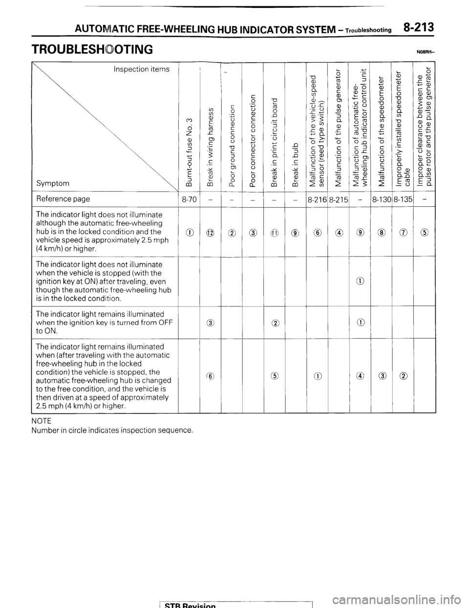
0 The indicator light does not illuminate
although the automatic free-wheeling
hub is in the locked condition and the
vehicle speed is approximately 2.5 mph
(4 km/h) or higher.
0 0 0
0
The indicator light does not illuminate
when the vehicle is stopped (with the
ignition key at ON) after traveling, even
though the automatic free-wheeling hub
is in the locked condition.
The indicator light remains illuminated
when the ignition key is turned from OFF
to ON.
0
0 0 0
a 0
The indicator light remains illuminated
when (after traveling with the automatic
free-wheeling hub in the locked
condition) the vehicle is stopped, the
automatic free-wheeling hub is changed
to the free condition, and the vehicle is
then driven at a speed of approximately
2.5 mph (4 km/h) or higher.
0 Cc 0
NOTE
Number in circle indicates inspection sequence.
/ STB Revision
Page 234 of 284
8-214 AUTOM TIC FREE-WHEELING VU6 INDICATOR SYSTEM - Circuit Diagram
I
m I IA-21 m
v?~
r:
BI I To column switch
2
[Refer to P.8-461 CT
= 9’i A I
I
m z
I ’
c: d
I ’
LR
!J
I I 1
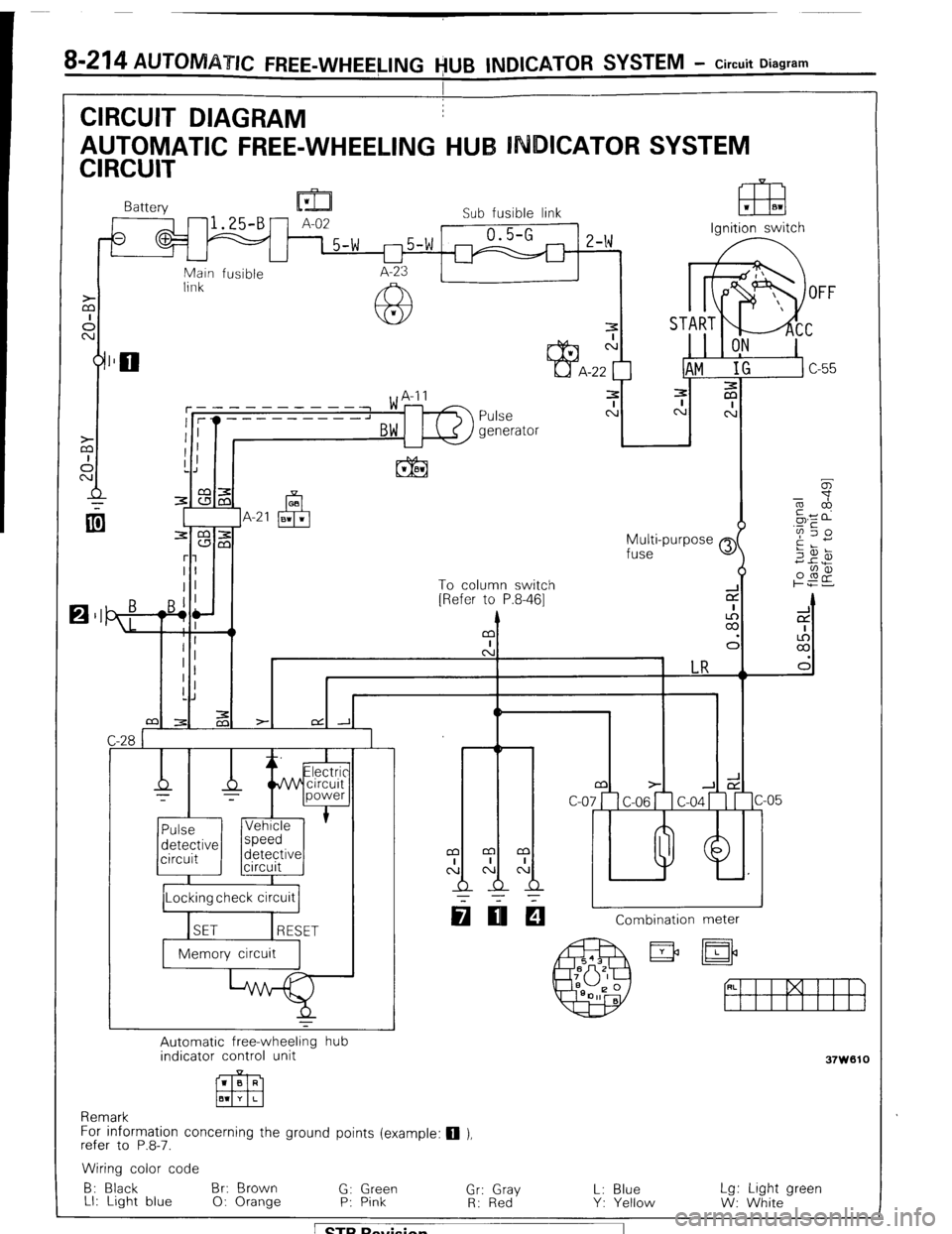
CIRCUIT DIAGRAM
AUTOMATIC FREE-WHEELING HUB INDICATOR SYSTEM
CIRCUIT
F==e=%
Battery lu-!
A-02 Sub fusible link
- 15-w r-)5-w 0.5-G
2-w
I I I I
Main fusible
link
7
N
-22
3
Pulse c:
generator
h Ignition switch
I /Locking check circuit 1
q IIEI Combination meter
Automatic free-wheeling hub
indicator control unit
1 B R
Em El1 Y L
Remark
For information concerning the ground points (example: q ),
refer to P.8-7.
37W610
Wiring color code
B: Black Br: Brown
G: Green L: Blue
LI: Light blue Lg: Light green
0: Orange P: Pink “,r: RG,‘d”Y
Y: Yellow
W: White
1 STB Revision
Page 235 of 284
AUTOMATIC FREE-WHEELING HUB INDICATOR SYSTEM - Pulse Generator 8-215
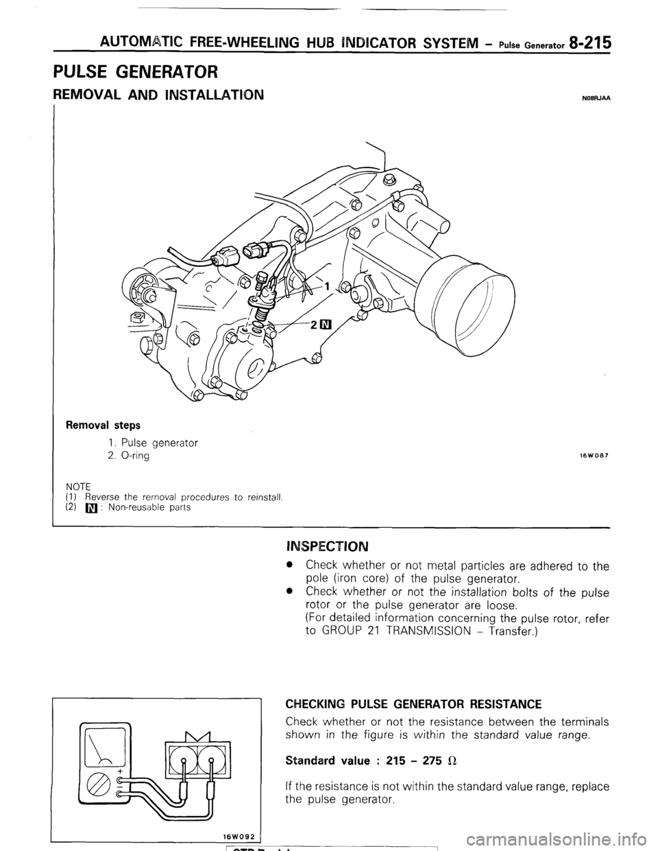
PULSE GENERATOR
REMOVAL AND INSTALLATION NOBRJM
Removal steps
I. Pulse generator
2. O-ring
NOTE
(1) Reverse the removal procedures to reinstall
(2)
q : Non-reusable parts
I 16WO92 i
l Check whether or not metal particles are adhered to the
pole (iron core) of the pulse generator.
l Check whether or not the installation bolts of the pulse
rotor or the pulse generator are loose.
(For detailed information concerning the pulse rotor, refer
to GROUP 21 TRANSMISSION - Transfer.)
CHECKING PULSE GENERATOR RESISTANCE
Check whether or not the resistance between the terminals
shown in the figure is within the standard value range.
Standard value : 215 - 275 LR
If the resistance is not within the standard value range, replace
the pulse generator.
1 STB Revision
Page 236 of 284
8-216 AUTOMATIC FREE-WHEELING HUB INDICATOR SYSTEM - Control Unit
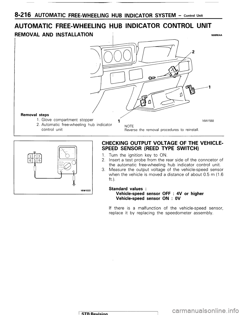
AUTOMATIC FREE-WHEELING HUB INDICATOR CONTROL UNIT
REMOVAL AND INSTALLATION
I NOBRKAA
Removal steps 1. Glove compartment stopper /
1 16W1568 2. Automatic free-wheeling hub indicator
NOTE control unit Reverse the removal procedures to reinstall.
CHECKING OUTPUT VOLTAGE OF THE VEHICLE-
SPE$D SENSOR (REED TYPE SWITCH) I. Turn the ignition key to ON.
2. Insert a test probe from the rear side of the conncetor of
the automatic free-wheeling hub indicator control unit.
3. Measure the output voltage of the vehicle-speed sensor
when the vehicle is moved a distance of about 0.5 m (1.6
ft.).
Standard values :
Vehicle-speed sensor OFF : 4V or higher
Vehicle-speed sensor ON : OV If there is a malfunction of the vehicle-speed sensor,
replace it by replacing the speedometer assembly.
( STB Revision
Page 237 of 284
24-1
AIR-CO IONING
CONTENTS
AIR-CONDITIONING
AIR CONDITIONER SWITCH ......................... 42
CIRCUIT DIAGRAM ...................................... . . 26
COMPRESSOR ............................................... 46
EVAPORATOR ............................................ . ... 43
GENERAL INFORMATION .............. . ....... . . . .... 19
RECEIVER DRIER, CONDENSER,
COMPRESSOR CLUTCH ASSEMBLY .......... 45
SAFETY PRECAUTIONS ................................ 28
SERVICE ADJUSTMENT PROCEDURES ...... 29
Compressor Drive Belt Adjustment ...........
40
Compressor Noise ..................................... 41
Handling Tubing and Fittings ..................... 39
Manifold Gauge Set Installation ................ 29
Performance Test ...................................... 34
Refrigerant Leak Repair Procedure ........... 34
Test Procedures ......................................... 29
Testing System for Leaks .......................... 33
SPECIAL TOOLS ............................................ 22
SPECIFICATIONS ...... . .
.. . ................................ 21
General Specifications ...............................
21
Service Specifications ................................
21
Torque Specifications ................................
21
TROUBLESHOOTING .................................... 22 Air is Emitted but Is Not Cool
Cool Air Flow Is Intermittent
Insufficient Air Flow
Insufficient Cooling
HEATERS
BLOWER ASSEMBLY . . . . . . . . . . . . . . . . . . ..a............... 14
CIRCUIT DIAGRAM . . . . . . . . . . . . . . . . . . . . . . . . . . . . . . . . . . . . . . . . 4
GENERAL INFORMATION . . . . . . . . . . . . . . . . . . . . . . . . . . . . . 2
HEATER CONTROL . . . . . . . . . . . . . . . . . . . . . . . . . . . . . . . . . . . . . . . . 9
HEATER UNIT . . . . . . . . . . . . . . . . . . . . . . . . . . . . . . . . . . . . . . . . . . . . . . . . . 12
SERVICE ADJUSTMENT PROCEDURES . . . . . . 5
Temperature Control System
Adjustment . . . . . . . . . . . . . . . . . . . . . . . . . . . . . . . . . . . . . . . . . . . . . . . . 5
Water Valve Replacement . . . . . . . . . . . . . . . . . . . . . . . 8
TROUBLESHOOTING . . . . . . . . . . . . . . . . . . . . . . . . . . . . . . . . . . . . 3
Blower Motor Inoperative
Blower Motor Operates on High
Speed Only
Improper Heat
No Ventilation Even When Mode
Selection Lever Is Operated
VENTILATORS . . . . . . . . . . . . . . . . . . . . . . . . . . . ..a..... . . . . . . . . . . . .
16
Page 238 of 284
24-2 HEATERS - General Information
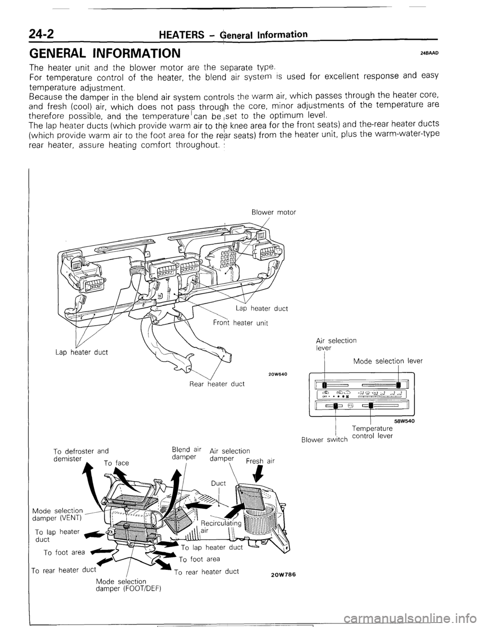
GENERAL INFORMATION 24BAAD
The heater unit and the blower motor are the separate type.
For temperature control of the heater, the blend air system is used for excellent response and easy
temperature adjustment.
Because the damper in the blend air system controls the warm air, which passes through the heater core,
and fresh (cool) air, which does not pass througlh the core, minor adjustments of the temperature are
therefore possible, and the temperature’can be ,set to the optimum level.
The lap heater ducts (which provide warm air to th$ knee area for the front seats) and the-rear heater ducts
(which provide warm air to the foot area for the rebr seats) from the heater unit, plus the warm-water-type
rear heater, assure heating comfort throughout. :
Blower motor
/
2OW640
Rear heater duct ;;eselection
I Mode selection lever
I I
58W540 Temperature
Blower switch contra’ lever To defroster and
Blend air Air selection
demister damper damper
Fresh air
Mode selection
damper (VENT) To lap heater &@
duct To foot area
ro rear heater duct To rear heater duct 2OW706 Mode selection damper (FOOT/DEF)
1 ST6 Revision
Page 239 of 284
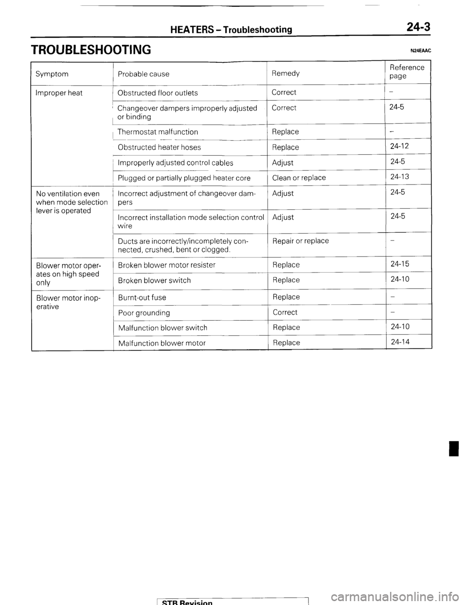
TROUBLESHOOTING
HEATERS -Troubleshooting 24-3
N24EAAC
Reference
Symptom Probable cause Remedy
paw
Improper heat Obstructed floor outlets Correct -
’ Changeover dampers improperly adjusted Correct 24-5
or binding
, Thermostat malfunction
Replace -
Obstructed heater hoses
Replace 24-l 2
’ Improperly adjusted control cables
Adjust 24-5
Plugged or partially plugged heater core
Clean or replace 24-l 3
No ventilation even Incorrect adjustment of changeover dam-
Adjust 24-5
when mode selection pers
lever is operated
Incorrect installation mode selection control
Adjust 24-5
wire
Blower motor oper-
ates on high speed
only
Blower motor inop-
erative Ducts are incorrectly/incompletely con-
netted, crushed, bent or clogged.
Broken blower motor resister
Broken blower switch
Burnt-out fuse
Poor grounding
Malfunction blower switch
Malfunction blower motor Repair or replace
Replace
Replace
Replace
Correct
Replace
Replace -
24-l 5
24-l 0
-
-
24-l 0
24-l 4 1 STB Revision
Page 240 of 284
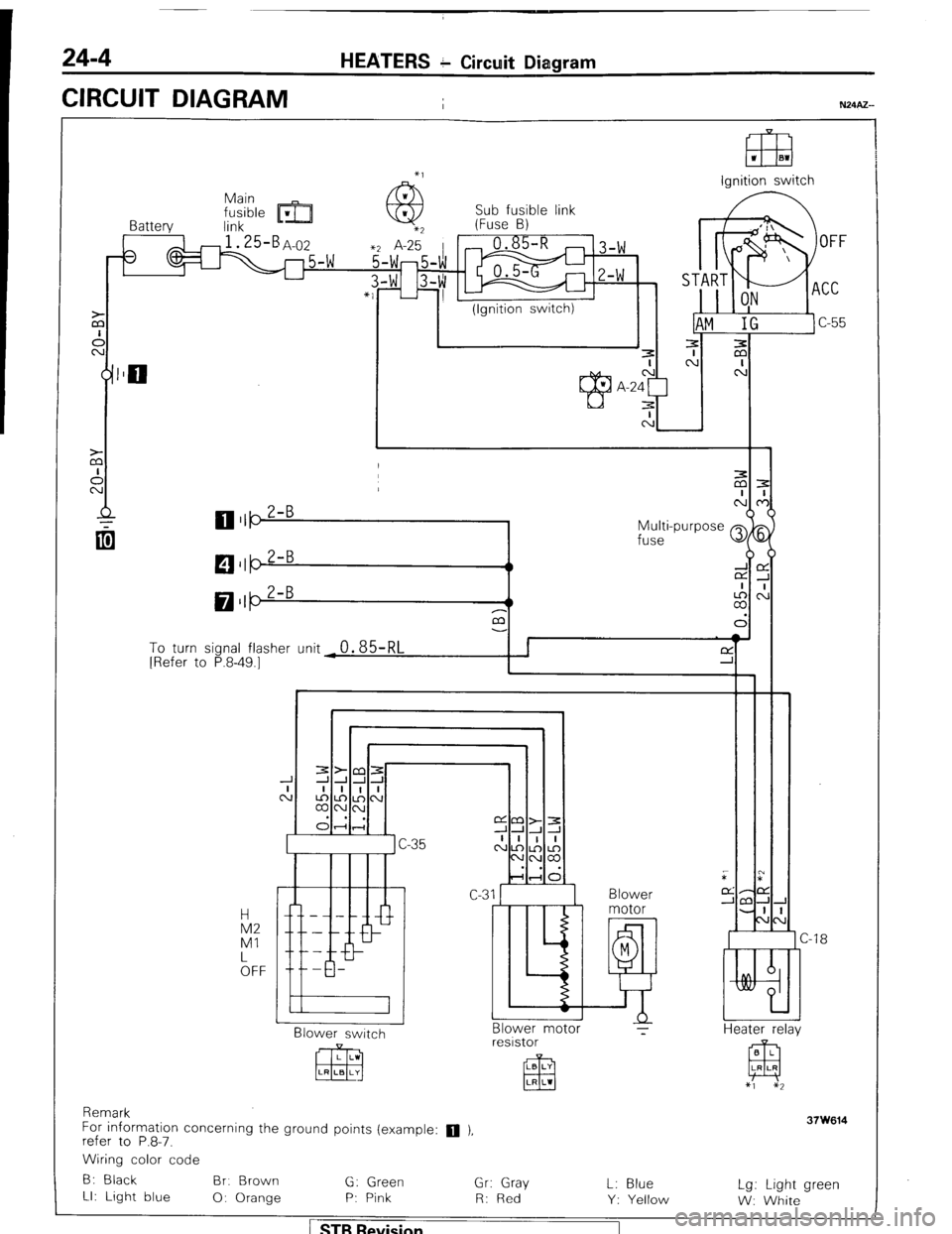
24-4 HEATERS c Circuit Diagram
CIRCUIT DIAGRAM
I
El3 1 El1
lanition switch
Sub fusible link
Battery link m- (Fuse B)
3
1 I (Ignition switch)
Multi-purpose Q
fuse
M $5
LA,:
a3
To turn sional flasher (Init
0.85RI I I f-Y ’ I [Refer to P.8-49.7- - - ‘d -r i
I Blower
Blower switch
CJ -18
Heater r&v Blower motor ?
resistor
Remark
For information concerning the ground points (example:
q ),
refer to P.8-7.
Wiring color code
B: Black Br. Brown
G: Green
Gr: Gray
LI: Light blue
0: Orange P: Pink
R: Red L: Blue
Y: Yellow Lg: Light green
W: White
1 STB Revision