MITSUBISHI MONTERO 1987 1.G Workshop Manual
Manufacturer: MITSUBISHI, Model Year: 1987, Model line: MONTERO, Model: MITSUBISHI MONTERO 1987 1.GPages: 284, PDF Size: 14.74 MB
Page 251 of 284
HEATERS - Blower Assembly 24-15
--I
Front wirina harness
d
!
2OW537
2OW768
2OW779
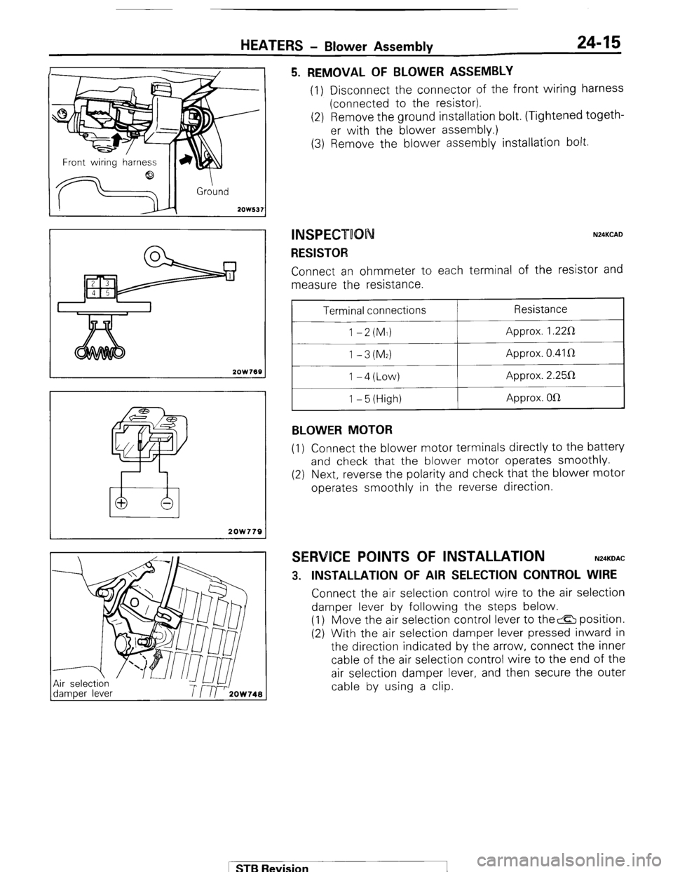
5. REMOVAL OF BLOWER ASSEMBLY (1) Disconnect the connector of the front wiring harness
(connected to the resistor).
(2) Remove the ground installation bolt. (Tightened togeth-
er with the blower assembly.)
(3) Remove the blower assembly installation bolt.
INSPECT00 N24KCAD
RESISTOR Connect an ohmmeter to each terminal of the resistor and
measure the resistance.
Terminal connections
1 -2(M1)
1 -3(M2) I-4(Low)
1 - 5 (High)
BLOWER MOTOR Resistance
Approx. 1.22R
Approx. 0.41 R
Approx. 2.25112
Approx. OlR
(1) Connect the blower motor terminals directly to the battery
and check that the blower motor operates smoothly.
(2) Next, reverse the polarity and check that the blower motor
operates smoothly in the reverse direction.
SERVICE POINTS OF INSTALLATION N24KDAC
3. INSTALLATION OF AIR SELECTION CONTROL WIRE Connect the air selection control wire to the air selection
damper lever by following the steps below.
(1) Move the air selection control lever to the& position.
(2) With the air selection damper lever pressed inward in
the direction indicated by the arrow, connect the inner
cable of the air selection control wire to the end of the
air selection damper lever, and then secure the outer
cable by using a clip.
1 STB Revision
Page 252 of 284
24-16 HEATER? - Ventilators
VENTILATORS
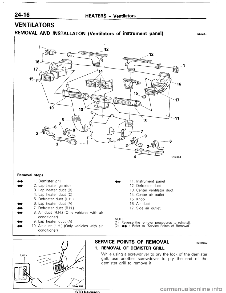
REMOVAL AND INSTALLATON (Ventilators of instrument panel) N24MA-
‘16
zowaa I4
Removal steps
1. Demister grill
2. Lap heater garnish
3. Lap heater duct (B)
4. Lap heater duct (C)
5. Defroster duct (L.H.)
6. Lap heater duct (A)
7. Defroster duct (R.H.)
8. Air duct (R.H.) (Only vehicles with air
conditioner)
9. Lap heater duct (A)
10. Air duct (L.H.) (Only vehicles with air
conditioner) 11. Instrument panel
12. Defroster duct
13. Center ventilator duct
14. Center air outlet
15. Knob
16. Air duct
17. Side air outlet
NOTE
(1) Reverse the removal procedures to reinstall.
(2) +e : Refer to “Service Points of Removal”
SERVICE POINTS OF REMOVAL N24MBAG
1. REMOVAL OF DEMISTER GRILL
While using a screwdriver to pry the lock of the demister
grill, use another screwdriver to pry the end of the
demister grill to remove it.
levision
Page 253 of 284
HEATERS - Ventilators 24-17
2OW75l
2OW759
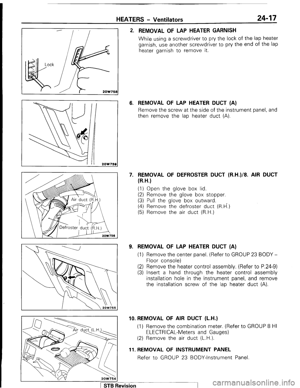
2. REMOVAL OF LAP HEATER GARNISH
While using a screwdriver to pry the lock of the lap heater
garnish, use another screwdriver to pry the end of the lap
heater garnish to remove it.
6. REMOVAL OF LAP HEATER DUCT (A)
Remove the screw at the side of the instrument panel, and
then remove the lap heater duct (A).
7. REMOVAL OF DEFROSTER DUCT (R.H.)/8. AIR DUCT
(R.H.)
(1) Open the glove box lid.
(2) Remove the glove box stopper.
(3) Pull the glove box outward.
(4) Remove the defroster duct (R.H’.)
(5) Remove the air duct (R.H.)
9. REMOVAL OF LAP HEATER DUCT (A)
(1) Remove the center panel. (Refer to GROUP 23 BODY -
Floor console)
(2) Remove the heater control assembly. (Refer to P.24-9)
(3) Insert a hand through the heater control assembly
installation hole in the instrument panel, and remove
the installation screw of the lap heater duct (A).
1 STB Revision 10. REMOVAL OF AIR DUCT (L.H.)
(1) Remove the combination meter. (Refer to GROUP 8 HI
ELECTRICAL-Meters and Gauges)
(2) Remove the air duct (L.H.).
11. REMOVAL OF INSTRUMENT PANEL
Refer to GROUP 23 BODY-Instrument Panel.
Page 254 of 284
24-18 HEATERS - Ventilators
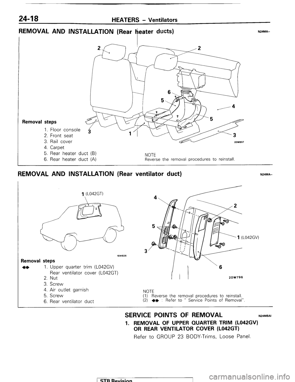
REMOVAL AND INSTALLATION [Rear heater ducts)
I 7F-T 'f------A
1
Removal steps 1. Floor console
2. Front seat
3. Rail cover
2ow.307 4. Carpet
5. Rear heater duct (B)
6. Rear heater duct (A)
NOTE
Reverse the removal procedures to reinstall.
REMOVAL AND INSTALLATION (Rear ventilator duct) N24MA-
1 (L042GT)
18W825
Removal steps
*I) 1. Upper quarter trim (L042GV)
Rear ventilator cover (L042GT)
2. Nut
3. Screw
4. Air outlet garnish
5. Screw
6. Rear ventilator duct
3
2OW796
NOTE
(1) Reverse the removal procedures to reinstall.
(2) +e : Refer to ” Service Points of Removal”.
SERVICE POINTS OF REMOVAL N24MBAI
1. REMOVAL OF UPPER QUARTER TRIM (L042GV)
OR REAR VENTILATOR COVER (L042GT) Refer to GROUP 23 BODY-Trims, Loose Panel.
( STB Revision
Page 255 of 284
AIR-CONDITIONING-General Information 24-19
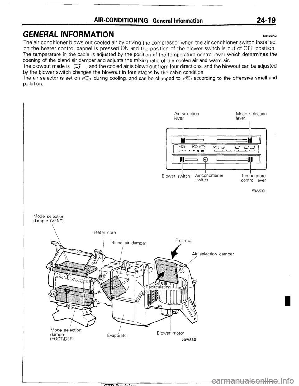
GENERAL INFORMATION N2400AC
The air conditioner blows out cooled air by driving the compressor when the air conditioner switch installed
on the heater control papnel is pressed ON and the position of the blower switch is out of OFF position.
The temperature in the cabin is adjusted by the position of the temperature control lever which determines the
opening of the blend air damper and adjusts the mixing ratio of the cooled air and warm air.
The blowout made is ‘z , and the cooled air is blown out from four directions, and the blowout can be adjusted
by the blower switch changes the blowout in four stages by the cabin condition.
The air selector is set on P&J during cooling, and can be changed to & according to the offensive smell and
pollution.
$;e;election
I Mode selection
lever
I
Blower sditch Air-cdnditioner
switch Temberature
control lever
58W539
Mode selection
damper (VENT)
Heater core
Fresh air
Mode selkction
damper
(FOOT/DEF) Evapdrator Blower! motor
2OW830
selection damper STB Revision
1
Page 256 of 284
24-20 AIR-CONDITION!NG-General Information
I
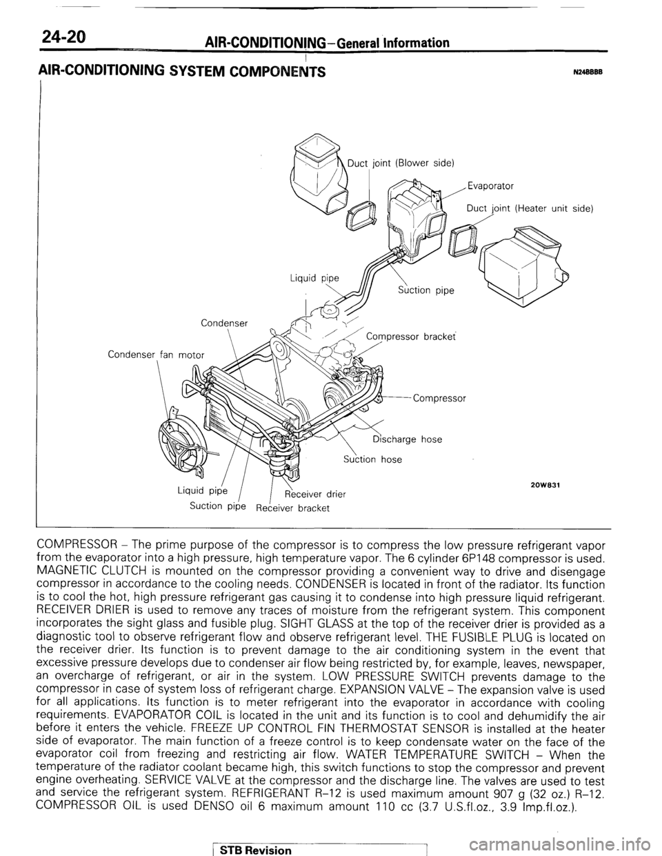
AIR-CONDITIONING SYSTEM COMPO
N24BBBB
Condenser MDuct, joint (Blower side)
oint (Heater unit
Condenser
2OWB31
Suction Pipe Receiver bracket side)
COMPRESSOR - The prime purpose of the compressor is to compress the low pressure refrigerant vapor
from the evaporator into a high pressure, high temperature vapor. The 6 cylinder 6P148 compressor is used.
MAGNETIC CLUTCH is mounted on the compressor providing a convenient way to drive and disengage
compressor in accordance to the cooling needs. CONDENSER is located in front of the radiator. Its function
is to cool the hot, high pressure refrigerant gas causing it to condense into high pressure liquid refrigerant.
RECEIVER DRIER is used to remove any traces of moisture from the refrigerant system. This component
incorporates the sight glass and fusible plug. SIGHT GLASS at the top of the receiver drier is provided as a
diagnostic tool to observe refrigerant flow and observe refrigerant level. THE FUSIBLE PLUG is located on
the receiver drier. Its function is to prevent damage to the air conditioning system in the event that
excessive pressure develops due to condenser air flow being restricted by, for example, leaves, newspaper,
an overcharge of refrigerant, or air in the system. LOW PRESSURE SWITCH prevents damage to the
compressor in case of system loss of refrigerant charge. EXPANSION VALVE - The expansion valve is used
for all applications. Its function is to meter refrigerant into the evaporator in accordance with cooling
requirements. EVAPORATOR COIL is located in the unit and its function is to cool and dehumidify the air
before it enters the vehicle. FREEZE UP CONTROL FIN THERMOSTAT SENSOR is installed at the heater
side of evaporator. The main function of a freeze control is to keep condensate water on the face of the
evaporator coil from freezing and restricting air flow. WATER TEMPERATURE SWITCH - When the
temperature of the radiator coolant became high, this switch functions to stop the compressor and prevent
engine overheating. SERVICE VALVE at the compressor and the discharge line. The valves are used to test
and service the refrigerant system. REFRIGERANT R-12 is used maximum amount 907 g (32 oz.) R-12.
COMPRESSOR OIL is used DENS0 oil 6 maximum amount 110 cc (3.7 U.S.fl.oz., 3.9 Imp.fl.oz.).
/ STB Revision
Page 257 of 284
AIR-CONDITIONING -Specifications
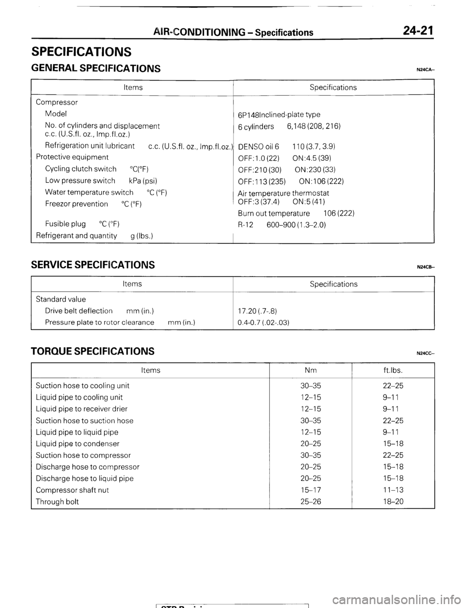
SPECIFICATIONS
GENERAL SPECIFICATIONS
24-2 1
N24CA-
Items Specifications
Compressor
Model
6P148lnclined-plate type
No. of cylinders and displacement
6 cylinders 6,148 (208,216)
cc. (U.S.fl. oz., Imp.fl.02.)
Refrigeration unit lubricant
cc. (U.S.fl. oz., Imp.fl.oz.) DENS0 oil 6 110 (3.7,3.9)
Protective equipment
OFF: 1 .O (22) ON:4.5 (39)
Cycling clutch switch
“C(“F)
OFF:210 (30) ON:230 (33)
Low pressure switch
kPa (psi)
OFF: 113 (235) ON:106(222)
Water temperature switch
“C (“F)
Air temperature thermostat
Freezor prevention
“C (“F) OFF:3 (37.4) ON:5 (41)
Burn out temperature 106 (222)
Fusible plug “C (“F)
R-l 2 600-900 (1.3-2.0)
Refrigerant and quantity
g (Ibs.1
SERVICE SPECIFICATIONS N24CE-
Items Specifications
Standard value
Drive belt deflection mm (in.) 17.20 (.7-.8)
Pressure plate to rotor clearance mm (in.)
0.4-0.7 (.02-.03)
TORQUE SPECIFICATIONS N24CG Items Nm ftlbs.
Suction hose to cooling unit 30-35 22-25
Liquid pipe to cooling unit 12-15 9-l 1
Liquid pipe to receiver drier 12-15 9-l 1
Suction hose to suction hose 30-35 22-25
Liquid pipe to liquid pipe 12-15 9-l 1
Liquid pipe to condenser 20-25 15-18
Suction hose to compressor 30-35 22-25
Discharge hose to compressor 20-25 15-18
Discharge hose to liquid pipe 20-25 15-18
Compressor shaft nut 15-17 11-13
Through bolt 25-26 18-20
/ STB Revision I
Page 258 of 284
24-22 AIR-CONDITIONING - Special TOOIS / Troubleshooting
SPECIAL TOOLS
Tool (Number and name)
MB990783-01
Steering/pinion gear
remover/installer Use
Installation of seal plate
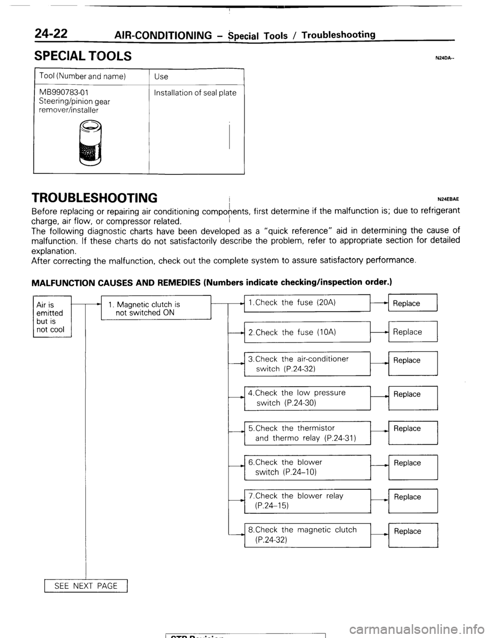
TROUBLESHOOTING N24EBAE
Before replacing or repairing air conditioning compofents, first determine if the malfunction is; due to refrigerant
charge, air flow, or compressor related.
The following diagnostic charts have been developed as a “quick reference” aid in determining the cause of
malfunction. If these charts do not satisfactorily describe the problem, refer to appropriate section for detailed
explanation.
N24DA.-
After correcting the malfunction, check out the complete system to assure satisfactory performance.
MALFUNCTION CAUSES AND REMEDIES (Numbers indicate checking/inspection order.)
1 not cool 1 Air is
emitted
but is * 1. Magnetic clutch is
not switched ON
SEE NEXT PAGE 1 Replace
1
I
I I
-4 2.Check the fuse (IOA)
t-l Replace
I
I I
I ,
I
3,Check the air-conditioner
__) Replace
switch (P.24-32)
I
4.Check the low pressure
switch (P.24-30) - Replace
---L 5.Check the thermistor
- Replace
and therm0 relay (P.24-31)
- 6.Check the blower
switch (P.24-10) - Replace
-i 7.Check the blower relay
M Replace
(P.24-15)
8.Check the magnetic clutch
(P.24-32) Replace
I
1 STB Revision
Page 259 of 284
![MITSUBISHI MONTERO 1987 1.G Workshop Manual AIR-CONDITIONING-Troubleshooting 24-23
1 CONTINUED FROM PREVIOUS PAGE] i
--) 2lnsufficient refrigerant
?
--) 3.Receiver drier clogged o Check the refrigerant amount _1 Supply
(P.24-29) refrigeran MITSUBISHI MONTERO 1987 1.G Workshop Manual AIR-CONDITIONING-Troubleshooting 24-23
1 CONTINUED FROM PREVIOUS PAGE] i
--) 2lnsufficient refrigerant
?
--) 3.Receiver drier clogged o Check the refrigerant amount _1 Supply
(P.24-29) refrigeran](/img/19/7559/w960_7559-258.png)
AIR-CONDITIONING-Troubleshooting 24-23
1 CONTINUED FROM PREVIOUS PAGE] i
--) 2lnsufficient refrigerant
?
--) 3.Receiver drier clogged o Check the refrigerant amount _1 Supply
(P.24-29) refrigerant
. Check the receiver drier
.--+ Replace
(P.24-29)
--. 4.Abnormal rotation of Drive belt loose
compresspor
* (P.24-40) __) Adjust the
belt
1
- 5.Expansion valve clogged ) Check the expansion valve - Replace
(P.24-44) t
- 6.Poor compression of
compressor c Check the compressor
(P.24-32)) - Replace
1 STB Revision
Page 260 of 284
AIR-CONDITIONING-Service Adjustment Procedures
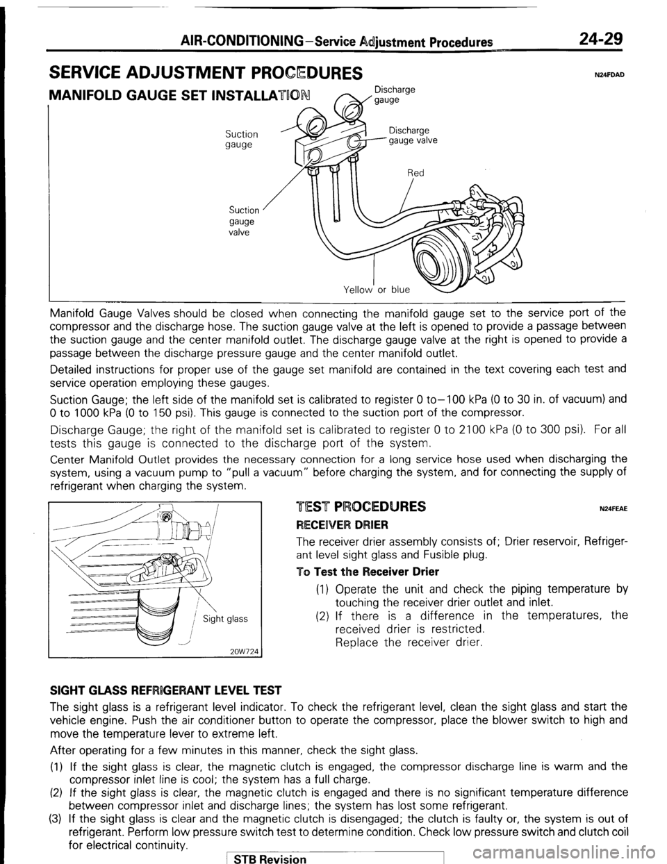
SERVICE ADJUSTMENT PROCQDURES 24-29 N24FDAD
MANIFOLD GAUGE SET INSTALLATUON Discharge
W gauge
Suction
gauge
Suction
gauge
valve Manifold Gauge Valves should be closed
when connecting the manifold gauge set to the service port of the
compressor and the discharge hose. The suction gauge valve at the left is opened to provide a passage between
the suction gauge and the center manifold outlet. The discharge gauge valve at the right is opened to provide a
passage between the discharge pressure gauge and the center manifold outlet.
Detailed instructions for proper use of the gauge set manifold are contained in the text covering each test and
service operation employing these gauges.
Suction Gauge; the left side of the manifold set is calibrated to register 0 to-100 kPa (0 to 30 in. of vacuum) and
0 to 1000 kPa (0 to 150 psi). This gauge is connected to the suction port of the compressor.
Discharge Gauge; the right of the manifold set is calibrated to register 0 to 2100 kPa (0 to 300 psi). For all
tests this gauge is connected to the discharge port of the system.
Center Manifold Outlet provides the necessary connection for a long service hose used when discharging the
system, using a vacuum pump to “pull a vacuum” before charging the system, and for connecting the supply of
refrigerant when charging the system
glass -
2OW724 N24FEAE The receiver drier assembly consists of; Drier reservoir, Refriger-
ant level sight glass and Fusible plug.
To Test the Receiver Drier (1) Operate the unit and check the piping temperature by
touching the receiver drier outlet and inlet.
(2) If there is a difference in the temperatures, the
received drier is restricted.
Replace the receiver drier.
SIGHT GLASS REFRlGERANT LEVEL TEST The sight glass is a refrigerant level indicator. To check the refrigerant level, clean the sight glass and start the
vehicle engine. Push the air conditioner button to operate the compressor, place the blower switch to high and
move the temperature lever to extreme left.
After operating for a few minutes in this manner, check the sight glass.
(1) If the sight glass is clear, the magnetic clutch is engaged, the compressor discharge line is warm and the
compressor inlet line is cool; the system has a full charge.
(2) If the sight glass is clear, the magnetic clutch is engaged and there is no significant temperature difference
between compressor inlet and discharge lines; the system has lost some refrigerant.
(3) If the sight glass is clear and the magnetic clutch is disengaged; the clutch is faulty or, the system is out of
refrigerant. Perform low pressure switch test to determine condition. Check low pressure switch and clutch coil
for electrical continuity.
1 STB Revision